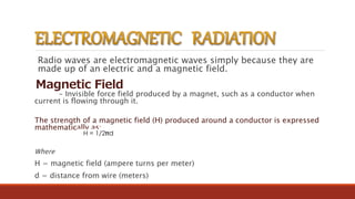
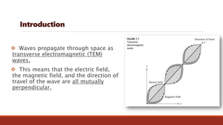
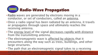
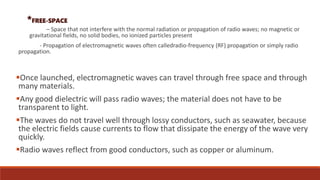
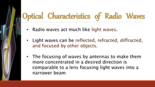
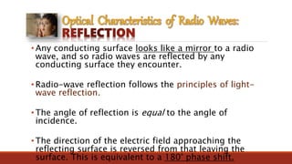
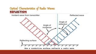
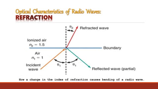
SlideShare a Scribd company logo
Transfer of electromagnetic waves or radio waves from one point
to another
• Electrical energy that has escaped into free space.
• It travels in a straight line at approximately the speed of light and are made of magnetic and electric
fields that are right angles to each other and right angles to the direction of propagation.
• Other forms include infrared, ultraviolet, X rays, and gamma rays.
TWO COMPONENTS:
 Electric Field= E
 Magnetic Field= H
• Form of electromagnetic radiation similar to light and heat.
• They differ from these other radiations in the manner in which they are generated and detected and in
their frequency range.
• It consists of traveling electric and magnetic fields, with the energy evenly divided between two types of
fields
The essential properties of radio waves are frequency, intensity, direction travel, and
plane of polarization.
Frequency (f) - is the number of cycles per second of a wave
Wavelength (λ) - is the distance that a wave travels in the time of one
cycle
Wave Velocity (c) - is the speed of the wave depending on the type and
nature of the propagation of the medium.
It travels fastest on FREE SPACE
λ= c/f
c = 3x10⁸ m/s
POLARIZATION
The polarization of a wave is the direction of the
electric field vector.
• Refers to the physical orientation of the radiated
waves in space dictated by the direction of the
electric field
• Polarization may be horizontal or vertical and can
also be circular or elliptical if the electric field vector
rotates as it moves through space.
Linear Polarization
- Electric vector has a particular direction in free
space
- Waves have the same alignment in space
VERTICAL– Electrical vector is vertical, or it lies
in a vertical plane.
HORIZONTAL– Electrical vector is horizontal, or
it lies in a horizontal plane
- Electric vector rotates about the axis of the
direction of propagation
Elliptical Polarization
- Electric vector rotates about the axis of the
direction of propagation but the amplitudes of
its two linearly polarized components are
unequal
Circular Polarization
Random Polarization
- There is no fixed pattern of polarization va
Isotropic Source
- Radiates uniformly in all possible
direction in space
 RAYS AND WAVEFRONTS are aids to illustrating the effects of
electromagnetic wave propagation through free space.
 RAY – is a line drawn along the direction of propagation of an
electromagnetic wave
– is used to show the relative direction of electromagnetic wave
propagation; however it does not necessarily represent the propagation
of a single electromagnetic wave.
 WAVEFRONT – shows a surface of constant phase of electromagnetic
wave
– is formed when points of equal phase on rays propagated
from the same source are joined together.
o The figure shows a wavefront with a surface that is perpendicular to the
direction of propagation (rectangle ABCD).
o When a surface is plane, its wavefront is perpendicular to the direction
of propagation. The closer to the source, the more complicated the
wavefront becomes.
A plane wave
 POINT SOURCE – is a single location from which rays propagate equally in all
directions (an isotropic source).
• The figure shows a point source, several rays propagating from it, and the
corresponding wavefront.
A wavefront from a point source.
o The wavefront generated from a point source is simply a sphere
with radius R and its center located at the point of origin of the
waves.
o In free space and a sufficient distance from the source, the rays
within a small area of a spherical wavefront are nearly parallel.
o The farther from the source, the more wave propagation appears
as a plane wavefront.
Radio waves are electromagnetic waves simply because they are
made up of an electric and a magnetic field.
Magnetic Field
- Invisible force field produced by a magnet, such as a conductor when
current is flowing through it.
The strength of a magnetic field (H) produced around a conductor is expressed
mathematically as:
Where
H = magnetic field (ampere turns per meter)
d = distance from wire (meters)
Electric fields
Invisible force fields produced by a difference in voltage potential between two conductors.
Electric filed strength (E) is expressed mathematically as:
Where:
E = electric field strength (volts per meter)
Q = charge between conductors (coulombs)
∈ = permittivity (farads per meter)
d = distance between conductors (meters)
*Permittivity
- Is the electric constant of the material separating the two conductors.
- The permittivityof air or space is approximately 8.85 x 10^-12 F/m.k
Introduction
 Waves propagate through space as
transverse electromagnetic (TEM)
waves.
 This means that the electric field,
the magnetic field, and the direction of
travel of the wave are all mutually
perpendicular.
Radio-Wave Propagation
• Radio waves are generated by electrons moving in a
conductor, or set of conductors, called an antenna.
• Once a radio signal has been radiated by an antenna, it travels
or propagates through space and ultimately reaches the
receiving antenna.
• The energy level of the signal decreases rapidly with distance
from the transmitting antenna.
• The electromagnetic wave is affected by objects that it
encounters along the way such as trees, buildings, and other
large structures.
• The path that an electromagnetic signal takes to a receiving
antenna depends upon many factors, including the frequency
*FREE-SPACE
– Space that not interfere with the normal radiation or propagation of radio waves; no magnetic or
gravitational fields, no solid bodies, no ionized particles present
- Propagation of electromagnetic waves often calledradio-frequency (RF) propagation or simply radio
propagation.
Once launched, electromagnetic waves can travel through free space and through
many materials.
Any good dielectric will pass radio waves; the material does not have to be
transparent to light.
The waves do not travel well through lossy conductors, such as seawater, because
the electric fields cause currents to flow that dissipate the energy of the wave very
quickly.
Radio waves reflect from good conductors, such as copper or aluminum.
The speed of propagation of radio waves in free space is the same as that of light,
approximately 300 × 106 m/s. In other media, the velocity is lower.
The propagation velocity is given by
where
 POWER DENSITY – the rate at which energy passes through a given surface
area in free space. It is energy per unit time per unit of area and is usually
given in watts per square meter.
where: P = power density (watts per meter squared)
E = rms electric field intensity (volts per meter)
H = rms magnetic field intensity (ampere turns per meter)
 FIELD INTENSITY – is the intensity of the electric and magnetic fields of an
electromagnetic wave propagating in free space.
 The electric and magnetic field intensities of an electromagnetic wave in
free space are related through the characteristic impedance (resistance) of
free space.
 The characteristics impedance of a lossless transmission medium is equal
to the square root of the ratio of its magnetic permeability to its electric
permittivity.
where: Zs = characteristic impedance of free space (ohms)
µo = magnetic permeability of free space (1.26 x 10⁻⁶ H/m)
o = electric permittivity of free space (8.85 x 10⁻¹² F/m)
substituting into the equation;
therefore, using Ohm’s law:
 ISOTROPIC RADIATOR – a point source that radiates power at
a constant rate uniformly in all directions and is
closely approximated by an omnidirectional antenna.
 An isotropic radiator produces a spherical wavefront
with radius R. All points distance R from the source lie on
the surface of the sphere and have equal power densities.
spherical wavefront
from an isotropic
source
 The power density at any point on the sphere is the total radiated power
divided by the total area of the sphere.
 power density at any point on the surface of a spherical
wavefront:
 INVERSE SQUARE LAW – the power density is inversely proportional to the square of the
distance from the source.
 The power density at any point on the surface of the outer sphere is:
 The power density at any point on the surface of the inner sphere is:
Therefore,
o As the distance from the source doubles, the power
density decreases by a factor of 22 or 4.
o When deriving the inverse square law of radiation, it
was assumed that the source radiates isotropically,
although it is not necessary; however, it is necessary
that the velocity of propagation in all directions be
uniform. Such a propagation medium is called an
isotropic medium.
 WAVE ATTENUATION – the reduction in power density due to the inverse
square law presumes free-space propagation (a vacuum or nearly a vacuum)
– sometimes called the space attenuation of the wave
because the attenuation is due to the spherical spreading of the wave.
 Wave attenuation is generally expressed in terms of the common logarithm
of the power density ratio (dB loss) . Mathematically;
 ABSORPTION – the reduction in power density due to nonfree-
space propagation.
 Since absorption of energy is dependent on the collision of
particles, the greater the particle density, the greater the
probability of collisions and the greater the absorption.
 For a homogeneous medium (one with uniform properties
throughout), the absorption experienced during the first mile of
propagation is the same as for the last mile.
 Atmospheric absorption ɳ for a wave propagating from R1 to
R2 is: ϒ (R2 – R1), where ϒ is the absorption coefficient.
 Wave attenuation depends on the ratio R2/R1, and wave
absorption depends on the distance between R1 and R2.
• Radio waves act much like light waves.
• Light waves can be reflected, refracted, diffracted,
and focused by other objects.
• The focusing of waves by antennas to make them
more concentrated in a desired direction is
comparable to a lens focusing light waves into a
narrower beam.
• Any conducting surface looks like a mirror to a radio
wave, and so radio waves are reflected by any
conducting surface they encounter.
• Radio-wave reflection follows the principles of light-
wave reflection.
• The angle of reflection is equal to the angle of
incidence.
• The direction of the electric field approaching the
reflecting surface is reversed from that leaving the
surface. This is equivalent to a 180° phase shift.
How a conductive surface reflects a radio wave.
◦ Refraction is the bending of a wave due to the physical makeup
of the medium through which the wave passes.
◦ Index of refraction is obtained by dividing the speed of a light
(or radio) wave in a vacuum and the speed of a light (or radio)
wave in the medium that causes the wave to be bent.
◦ The relationship between the angles and the indices of refraction
is given by a formula known as Snell’s law:
n1 sin Θ1 = n2 sin Θ2
where
n1 = index of refraction of initial medium
n2 = index of refraction of medium into which wave passes
Θ1 = angle of incidence
Θ2 = angle of refraction
How a change in the index of refraction causes bending of a radio wave.
Diffraction is the bending of waves around an
object.
Diffraction is explained by Huygen’s Principle:
◦ Assuming that all electromagnetic waves radiate as spherical waveforms from
a source, each point on a wave front can be considered as a point source for
additional spherical waves.
◦ When the waves encounter an obstacle, they pass around it, above it, and on
either side.
◦ As the wave front passes the object, the point sources of waves at the edge of
the obstacle create additional spherical waves that penetrate and fill in the
shadow zone.
Diffraction causes waves to bend around obstacles.

More Related Content

What's hot

Reflex klystron amplifier , microwave klystron amplifier
Reflex klystron amplifier , microwave klystron amplifierReflex klystron amplifier , microwave klystron amplifier
Reflex klystron amplifier , microwave klystron amplifier
Kamal Bhagat
 
Satellite communication
Satellite   communicationSatellite   communication
Satellite communication
Satyajit Das
 
Antenas - Examen Final
Antenas - Examen FinalAntenas - Examen Final
Antenas - Examen Final
Andy Juan Sarango Veliz
 
Ee424 fading
Ee424 fadingEe424 fading
Ee424 fading
Shraddha Bansal
 
radio-wave-propagation-presentations
radio-wave-propagation-presentationsradio-wave-propagation-presentations
radio-wave-propagation-presentations
ATTO RATHORE
 
Presentation-3
Presentation-3Presentation-3
Presentation-3
Emran Hasan
 
Presentacion - FactoresAmbientales.pdf
Presentacion - FactoresAmbientales.pdfPresentacion - FactoresAmbientales.pdf
Presentacion - FactoresAmbientales.pdf
veronicasalazardeDia
 
Antennas wave and propagation
 Antennas wave and propagation Antennas wave and propagation
Antennas wave and propagation
Isha Negi
 
Microstrip Patch Antenna Design
Microstrip Patch Antenna DesignMicrostrip Patch Antenna Design
Microstrip Patch Antenna Design
Amit Samanta
 
Link budget calculation
Link budget calculationLink budget calculation
Link budget calculation
sitimunirah88
 
HF Communication Basics Part 2
HF Communication Basics Part 2HF Communication Basics Part 2
HF Communication Basics Part 2
Afghanistan civil aviation institute
 
Satellite Bands
Satellite BandsSatellite Bands
Satellite Bands
Waqas !!!!
 
Lecture 2 intro a sist radiocom p2
Lecture 2 intro a sist radiocom   p2Lecture 2 intro a sist radiocom   p2
Lecture 2 intro a sist radiocom p2
nica2009
 
Dominio del tiempo_y_de_la_frecuencia
Dominio del tiempo_y_de_la_frecuenciaDominio del tiempo_y_de_la_frecuencia
Dominio del tiempo_y_de_la_frecuencia
Gabo Rodríguez
 
Fundamentals of microwave communication system and radar systems
Fundamentals of microwave communication system and radar systemsFundamentals of microwave communication system and radar systems
Fundamentals of microwave communication system and radar systems
sabesh chaudhary
 
Microwave waveguides 1st 1
Microwave waveguides 1st 1Microwave waveguides 1st 1
Microwave waveguides 1st 1
HIMANSHU DIWAKAR
 
Proyecto antena yagi uda
Proyecto antena yagi udaProyecto antena yagi uda
Proyecto antena yagi uda
ELISEORODEA
 
Fm Transmitter and receiver
 Fm Transmitter and receiver Fm Transmitter and receiver
Fm Transmitter and receiver
nurnaser1234
 

What's hot (20)

Reflex klystron amplifier , microwave klystron amplifier
Reflex klystron amplifier , microwave klystron amplifierReflex klystron amplifier , microwave klystron amplifier
Reflex klystron amplifier , microwave klystron amplifier
 
Satellite communication
Satellite   communicationSatellite   communication
Satellite communication
 
Antenas - Examen Final
Antenas - Examen FinalAntenas - Examen Final
Antenas - Examen Final
 
Ee424 fading
Ee424 fadingEe424 fading
Ee424 fading
 
radio-wave-propagation-presentations
radio-wave-propagation-presentationsradio-wave-propagation-presentations
radio-wave-propagation-presentations
 
Presentation-3
Presentation-3Presentation-3
Presentation-3
 
Presentacion - FactoresAmbientales.pdf
Presentacion - FactoresAmbientales.pdfPresentacion - FactoresAmbientales.pdf
Presentacion - FactoresAmbientales.pdf
 
Antennas wave and propagation
 Antennas wave and propagation Antennas wave and propagation
Antennas wave and propagation
 
Microstrip Patch Antenna Design
Microstrip Patch Antenna DesignMicrostrip Patch Antenna Design
Microstrip Patch Antenna Design
 
Link budget calculation
Link budget calculationLink budget calculation
Link budget calculation
 
HF Communication Basics Part 2
HF Communication Basics Part 2HF Communication Basics Part 2
HF Communication Basics Part 2
 
Satellite Bands
Satellite BandsSatellite Bands
Satellite Bands
 
Lecture 2 intro a sist radiocom p2
Lecture 2 intro a sist radiocom   p2Lecture 2 intro a sist radiocom   p2
Lecture 2 intro a sist radiocom p2
 
Dominio del tiempo_y_de_la_frecuencia
Dominio del tiempo_y_de_la_frecuenciaDominio del tiempo_y_de_la_frecuencia
Dominio del tiempo_y_de_la_frecuencia
 
Fundamentals of microwave communication system and radar systems
Fundamentals of microwave communication system and radar systemsFundamentals of microwave communication system and radar systems
Fundamentals of microwave communication system and radar systems
 
Microwave waveguides 1st 1
Microwave waveguides 1st 1Microwave waveguides 1st 1
Microwave waveguides 1st 1
 
Proyecto antena yagi uda
Proyecto antena yagi udaProyecto antena yagi uda
Proyecto antena yagi uda
 
Receivers
ReceiversReceivers
Receivers
 
4. transmision
4. transmision4. transmision
4. transmision
 
Fm Transmitter and receiver
 Fm Transmitter and receiver Fm Transmitter and receiver
Fm Transmitter and receiver
 

Similar to Radio Wave Propagation

electromagnetic waves class 12 physics free study material
electromagnetic waves class 12 physics free study materialelectromagnetic waves class 12 physics free study material
electromagnetic waves class 12 physics free study material
Vivekanand Anglo Vedic Academy
 
radio propagation
radio propagationradio propagation
radio propagation
ATTO RATHORE
 
Electromagnetic Wave
Electromagnetic Wave Electromagnetic Wave
Electromagnetic Wave
Priyanka Jakhar
 
electromagnetic-wave-propagation
electromagnetic-wave-propagationelectromagnetic-wave-propagation
electromagnetic-wave-propagation
ATTO RATHORE
 
Class_12-Physics_ Alternating current and Electromagnetic Waves_ PPT-3 of 3.pdf
Class_12-Physics_ Alternating current and Electromagnetic Waves_ PPT-3 of 3.pdfClass_12-Physics_ Alternating current and Electromagnetic Waves_ PPT-3 of 3.pdf
Class_12-Physics_ Alternating current and Electromagnetic Waves_ PPT-3 of 3.pdf
MuskanShrivastava15
 
physics project class 12.pptx
physics project class 12.pptxphysics project class 12.pptx
physics project class 12.pptx
ShreyasGanesh4
 
Radio Wave propagation
Radio Wave propagationRadio Wave propagation
Radio Wave propagation
Ritika De
 
Rf antenna basics
Rf antenna basicsRf antenna basics
Rf antenna basics
Mansi Thakur
 
Electromagnetic waves BY- Rahul singh
Electromagnetic waves  BY- Rahul singh Electromagnetic waves  BY- Rahul singh
Electromagnetic waves BY- Rahul singh
Rahul Singh
 
EC6602-AWP unit 1
EC6602-AWP unit 1EC6602-AWP unit 1
EC6602-AWP unit 1
krishnamrm
 
EC6602-Antenna fundamentals new
EC6602-Antenna fundamentals new EC6602-Antenna fundamentals new
EC6602-Antenna fundamentals new
krishnamrm
 
Srikarsh Awp
Srikarsh AwpSrikarsh Awp
Srikarsh Awp
Kolanu Reddy
 
ANTENNA PARAMETERS.pptx
ANTENNA PARAMETERS.pptxANTENNA PARAMETERS.pptx
ANTENNA PARAMETERS.pptx
AkkuA3
 
Glossary of scientific terms to know.pdf
Glossary of scientific terms to know.pdfGlossary of scientific terms to know.pdf
Glossary of scientific terms to know.pdf
trungvo92
 
ELECTRO MAGNETIC RAIATIONS.pptx
ELECTRO MAGNETIC RAIATIONS.pptxELECTRO MAGNETIC RAIATIONS.pptx
ELECTRO MAGNETIC RAIATIONS.pptx
SYED MASOOD
 
Electro magnetic waves
Electro magnetic wavesElectro magnetic waves
Electro magnetic waves
Suganthi Thangaraj
 
Communication - Space Communication Class 12 Part-5
Communication - Space Communication Class 12 Part-5Communication - Space Communication Class 12 Part-5
Communication - Space Communication Class 12 Part-5Self-employed
 
electromagnetic_waves (1).ppt
electromagnetic_waves (1).pptelectromagnetic_waves (1).ppt
electromagnetic_waves (1).ppt
mitanshu11
 
electromagnetic_waves.ppt
electromagnetic_waves.pptelectromagnetic_waves.ppt
electromagnetic_waves.ppt
mragarwal
 

Similar to Radio Wave Propagation (20)

electromagnetic waves class 12 physics free study material
electromagnetic waves class 12 physics free study materialelectromagnetic waves class 12 physics free study material
electromagnetic waves class 12 physics free study material
 
radio propagation
radio propagationradio propagation
radio propagation
 
Electromagnetic Wave
Electromagnetic Wave Electromagnetic Wave
Electromagnetic Wave
 
electromagnetic-wave-propagation
electromagnetic-wave-propagationelectromagnetic-wave-propagation
electromagnetic-wave-propagation
 
Class_12-Physics_ Alternating current and Electromagnetic Waves_ PPT-3 of 3.pdf
Class_12-Physics_ Alternating current and Electromagnetic Waves_ PPT-3 of 3.pdfClass_12-Physics_ Alternating current and Electromagnetic Waves_ PPT-3 of 3.pdf
Class_12-Physics_ Alternating current and Electromagnetic Waves_ PPT-3 of 3.pdf
 
physics project class 12.pptx
physics project class 12.pptxphysics project class 12.pptx
physics project class 12.pptx
 
Radio Wave propagation
Radio Wave propagationRadio Wave propagation
Radio Wave propagation
 
Rf antenna basics
Rf antenna basicsRf antenna basics
Rf antenna basics
 
Electromagnetic waves BY- Rahul singh
Electromagnetic waves  BY- Rahul singh Electromagnetic waves  BY- Rahul singh
Electromagnetic waves BY- Rahul singh
 
EC6602-AWP unit 1
EC6602-AWP unit 1EC6602-AWP unit 1
EC6602-AWP unit 1
 
EC6602-Antenna fundamentals new
EC6602-Antenna fundamentals new EC6602-Antenna fundamentals new
EC6602-Antenna fundamentals new
 
Propagation Of Waves
Propagation Of WavesPropagation Of Waves
Propagation Of Waves
 
Srikarsh Awp
Srikarsh AwpSrikarsh Awp
Srikarsh Awp
 
ANTENNA PARAMETERS.pptx
ANTENNA PARAMETERS.pptxANTENNA PARAMETERS.pptx
ANTENNA PARAMETERS.pptx
 
Glossary of scientific terms to know.pdf
Glossary of scientific terms to know.pdfGlossary of scientific terms to know.pdf
Glossary of scientific terms to know.pdf
 
ELECTRO MAGNETIC RAIATIONS.pptx
ELECTRO MAGNETIC RAIATIONS.pptxELECTRO MAGNETIC RAIATIONS.pptx
ELECTRO MAGNETIC RAIATIONS.pptx
 
Electro magnetic waves
Electro magnetic wavesElectro magnetic waves
Electro magnetic waves
 
Communication - Space Communication Class 12 Part-5
Communication - Space Communication Class 12 Part-5Communication - Space Communication Class 12 Part-5
Communication - Space Communication Class 12 Part-5
 
electromagnetic_waves (1).ppt
electromagnetic_waves (1).pptelectromagnetic_waves (1).ppt
electromagnetic_waves (1).ppt
 
electromagnetic_waves.ppt
electromagnetic_waves.pptelectromagnetic_waves.ppt
electromagnetic_waves.ppt
 

Recently uploaded

Industrial Training at Shahjalal Fertilizer Company Limited (SFCL)
Industrial Training at Shahjalal Fertilizer Company Limited (SFCL)Industrial Training at Shahjalal Fertilizer Company Limited (SFCL)
Industrial Training at Shahjalal Fertilizer Company Limited (SFCL)
MdTanvirMahtab2
 
ASME IX(9) 2007 Full Version .pdf
ASME IX(9)  2007 Full Version       .pdfASME IX(9)  2007 Full Version       .pdf
ASME IX(9) 2007 Full Version .pdf
AhmedHussein950959
 
ethical hacking-mobile hacking methods.ppt
ethical hacking-mobile hacking methods.pptethical hacking-mobile hacking methods.ppt
ethical hacking-mobile hacking methods.ppt
Jayaprasanna4
 
J.Yang, ICLR 2024, MLILAB, KAIST AI.pdf
J.Yang,  ICLR 2024, MLILAB, KAIST AI.pdfJ.Yang,  ICLR 2024, MLILAB, KAIST AI.pdf
J.Yang, ICLR 2024, MLILAB, KAIST AI.pdf
MLILAB
 
Immunizing Image Classifiers Against Localized Adversary Attacks
Immunizing Image Classifiers Against Localized Adversary AttacksImmunizing Image Classifiers Against Localized Adversary Attacks
Immunizing Image Classifiers Against Localized Adversary Attacks
gerogepatton
 
Sachpazis:Terzaghi Bearing Capacity Estimation in simple terms with Calculati...
Sachpazis:Terzaghi Bearing Capacity Estimation in simple terms with Calculati...Sachpazis:Terzaghi Bearing Capacity Estimation in simple terms with Calculati...
Sachpazis:Terzaghi Bearing Capacity Estimation in simple terms with Calculati...
Dr.Costas Sachpazis
 
HYDROPOWER - Hydroelectric power generation
HYDROPOWER - Hydroelectric power generationHYDROPOWER - Hydroelectric power generation
HYDROPOWER - Hydroelectric power generation
Robbie Edward Sayers
 
Design and Analysis of Algorithms-DP,Backtracking,Graphs,B&B
Design and Analysis of Algorithms-DP,Backtracking,Graphs,B&BDesign and Analysis of Algorithms-DP,Backtracking,Graphs,B&B
Design and Analysis of Algorithms-DP,Backtracking,Graphs,B&B
Sreedhar Chowdam
 
power quality voltage fluctuation UNIT - I.pptx
power quality voltage fluctuation UNIT - I.pptxpower quality voltage fluctuation UNIT - I.pptx
power quality voltage fluctuation UNIT - I.pptx
ViniHema
 
Cosmetic shop management system project report.pdf
Cosmetic shop management system project report.pdfCosmetic shop management system project report.pdf
Cosmetic shop management system project report.pdf
Kamal Acharya
 
The role of big data in decision making.
The role of big data in decision making.The role of big data in decision making.
The role of big data in decision making.
ankuprajapati0525
 
ML for identifying fraud using open blockchain data.pptx
ML for identifying fraud using open blockchain data.pptxML for identifying fraud using open blockchain data.pptx
ML for identifying fraud using open blockchain data.pptx
Vijay Dialani, PhD
 
Final project report on grocery store management system..pdf
Final project report on grocery store management system..pdfFinal project report on grocery store management system..pdf
Final project report on grocery store management system..pdf
Kamal Acharya
 
CFD Simulation of By-pass Flow in a HRSG module by R&R Consult.pptx
CFD Simulation of By-pass Flow in a HRSG module by R&R Consult.pptxCFD Simulation of By-pass Flow in a HRSG module by R&R Consult.pptx
CFD Simulation of By-pass Flow in a HRSG module by R&R Consult.pptx
R&R Consult
 
Fundamentals of Electric Drives and its applications.pptx
Fundamentals of Electric Drives and its applications.pptxFundamentals of Electric Drives and its applications.pptx
Fundamentals of Electric Drives and its applications.pptx
manasideore6
 
DESIGN A COTTON SEED SEPARATION MACHINE.docx
DESIGN A COTTON SEED SEPARATION MACHINE.docxDESIGN A COTTON SEED SEPARATION MACHINE.docx
DESIGN A COTTON SEED SEPARATION MACHINE.docx
FluxPrime1
 
Architectural Portfolio Sean Lockwood
Architectural Portfolio Sean LockwoodArchitectural Portfolio Sean Lockwood
Architectural Portfolio Sean Lockwood
seandesed
 
Standard Reomte Control Interface - Neometrix
Standard Reomte Control Interface - NeometrixStandard Reomte Control Interface - Neometrix
Standard Reomte Control Interface - Neometrix
Neometrix_Engineering_Pvt_Ltd
 
一比一原版(UofT毕业证)多伦多大学毕业证成绩单如何办理
一比一原版(UofT毕业证)多伦多大学毕业证成绩单如何办理一比一原版(UofT毕业证)多伦多大学毕业证成绩单如何办理
一比一原版(UofT毕业证)多伦多大学毕业证成绩单如何办理
ydteq
 
Gen AI Study Jams _ For the GDSC Leads in India.pdf
Gen AI Study Jams _ For the GDSC Leads in India.pdfGen AI Study Jams _ For the GDSC Leads in India.pdf
Gen AI Study Jams _ For the GDSC Leads in India.pdf
gdsczhcet
 

Recently uploaded (20)

Industrial Training at Shahjalal Fertilizer Company Limited (SFCL)
Industrial Training at Shahjalal Fertilizer Company Limited (SFCL)Industrial Training at Shahjalal Fertilizer Company Limited (SFCL)
Industrial Training at Shahjalal Fertilizer Company Limited (SFCL)
 
ASME IX(9) 2007 Full Version .pdf
ASME IX(9)  2007 Full Version       .pdfASME IX(9)  2007 Full Version       .pdf
ASME IX(9) 2007 Full Version .pdf
 
ethical hacking-mobile hacking methods.ppt
ethical hacking-mobile hacking methods.pptethical hacking-mobile hacking methods.ppt
ethical hacking-mobile hacking methods.ppt
 
J.Yang, ICLR 2024, MLILAB, KAIST AI.pdf
J.Yang,  ICLR 2024, MLILAB, KAIST AI.pdfJ.Yang,  ICLR 2024, MLILAB, KAIST AI.pdf
J.Yang, ICLR 2024, MLILAB, KAIST AI.pdf
 
Immunizing Image Classifiers Against Localized Adversary Attacks
Immunizing Image Classifiers Against Localized Adversary AttacksImmunizing Image Classifiers Against Localized Adversary Attacks
Immunizing Image Classifiers Against Localized Adversary Attacks
 
Sachpazis:Terzaghi Bearing Capacity Estimation in simple terms with Calculati...
Sachpazis:Terzaghi Bearing Capacity Estimation in simple terms with Calculati...Sachpazis:Terzaghi Bearing Capacity Estimation in simple terms with Calculati...
Sachpazis:Terzaghi Bearing Capacity Estimation in simple terms with Calculati...
 
HYDROPOWER - Hydroelectric power generation
HYDROPOWER - Hydroelectric power generationHYDROPOWER - Hydroelectric power generation
HYDROPOWER - Hydroelectric power generation
 
Design and Analysis of Algorithms-DP,Backtracking,Graphs,B&B
Design and Analysis of Algorithms-DP,Backtracking,Graphs,B&BDesign and Analysis of Algorithms-DP,Backtracking,Graphs,B&B
Design and Analysis of Algorithms-DP,Backtracking,Graphs,B&B
 
power quality voltage fluctuation UNIT - I.pptx
power quality voltage fluctuation UNIT - I.pptxpower quality voltage fluctuation UNIT - I.pptx
power quality voltage fluctuation UNIT - I.pptx
 
Cosmetic shop management system project report.pdf
Cosmetic shop management system project report.pdfCosmetic shop management system project report.pdf
Cosmetic shop management system project report.pdf
 
The role of big data in decision making.
The role of big data in decision making.The role of big data in decision making.
The role of big data in decision making.
 
ML for identifying fraud using open blockchain data.pptx
ML for identifying fraud using open blockchain data.pptxML for identifying fraud using open blockchain data.pptx
ML for identifying fraud using open blockchain data.pptx
 
Final project report on grocery store management system..pdf
Final project report on grocery store management system..pdfFinal project report on grocery store management system..pdf
Final project report on grocery store management system..pdf
 
CFD Simulation of By-pass Flow in a HRSG module by R&R Consult.pptx
CFD Simulation of By-pass Flow in a HRSG module by R&R Consult.pptxCFD Simulation of By-pass Flow in a HRSG module by R&R Consult.pptx
CFD Simulation of By-pass Flow in a HRSG module by R&R Consult.pptx
 
Fundamentals of Electric Drives and its applications.pptx
Fundamentals of Electric Drives and its applications.pptxFundamentals of Electric Drives and its applications.pptx
Fundamentals of Electric Drives and its applications.pptx
 
DESIGN A COTTON SEED SEPARATION MACHINE.docx
DESIGN A COTTON SEED SEPARATION MACHINE.docxDESIGN A COTTON SEED SEPARATION MACHINE.docx
DESIGN A COTTON SEED SEPARATION MACHINE.docx
 
Architectural Portfolio Sean Lockwood
Architectural Portfolio Sean LockwoodArchitectural Portfolio Sean Lockwood
Architectural Portfolio Sean Lockwood
 
Standard Reomte Control Interface - Neometrix
Standard Reomte Control Interface - NeometrixStandard Reomte Control Interface - Neometrix
Standard Reomte Control Interface - Neometrix
 
一比一原版(UofT毕业证)多伦多大学毕业证成绩单如何办理
一比一原版(UofT毕业证)多伦多大学毕业证成绩单如何办理一比一原版(UofT毕业证)多伦多大学毕业证成绩单如何办理
一比一原版(UofT毕业证)多伦多大学毕业证成绩单如何办理
 
Gen AI Study Jams _ For the GDSC Leads in India.pdf
Gen AI Study Jams _ For the GDSC Leads in India.pdfGen AI Study Jams _ For the GDSC Leads in India.pdf
Gen AI Study Jams _ For the GDSC Leads in India.pdf
 

Radio Wave Propagation

  • 1.
  • 2. Transfer of electromagnetic waves or radio waves from one point to another • Electrical energy that has escaped into free space. • It travels in a straight line at approximately the speed of light and are made of magnetic and electric fields that are right angles to each other and right angles to the direction of propagation. • Other forms include infrared, ultraviolet, X rays, and gamma rays. TWO COMPONENTS:  Electric Field= E  Magnetic Field= H • Form of electromagnetic radiation similar to light and heat. • They differ from these other radiations in the manner in which they are generated and detected and in their frequency range. • It consists of traveling electric and magnetic fields, with the energy evenly divided between two types of fields
  • 3. The essential properties of radio waves are frequency, intensity, direction travel, and plane of polarization. Frequency (f) - is the number of cycles per second of a wave Wavelength (λ) - is the distance that a wave travels in the time of one cycle Wave Velocity (c) - is the speed of the wave depending on the type and nature of the propagation of the medium. It travels fastest on FREE SPACE λ= c/f c = 3x10⁸ m/s
  • 4. POLARIZATION The polarization of a wave is the direction of the electric field vector. • Refers to the physical orientation of the radiated waves in space dictated by the direction of the electric field • Polarization may be horizontal or vertical and can also be circular or elliptical if the electric field vector rotates as it moves through space.
  • 5. Linear Polarization - Electric vector has a particular direction in free space - Waves have the same alignment in space VERTICAL– Electrical vector is vertical, or it lies in a vertical plane. HORIZONTAL– Electrical vector is horizontal, or it lies in a horizontal plane - Electric vector rotates about the axis of the direction of propagation Elliptical Polarization - Electric vector rotates about the axis of the direction of propagation but the amplitudes of its two linearly polarized components are unequal Circular Polarization Random Polarization - There is no fixed pattern of polarization va Isotropic Source - Radiates uniformly in all possible direction in space
  • 6.  RAYS AND WAVEFRONTS are aids to illustrating the effects of electromagnetic wave propagation through free space.  RAY – is a line drawn along the direction of propagation of an electromagnetic wave – is used to show the relative direction of electromagnetic wave propagation; however it does not necessarily represent the propagation of a single electromagnetic wave.  WAVEFRONT – shows a surface of constant phase of electromagnetic wave – is formed when points of equal phase on rays propagated from the same source are joined together.
  • 7. o The figure shows a wavefront with a surface that is perpendicular to the direction of propagation (rectangle ABCD). o When a surface is plane, its wavefront is perpendicular to the direction of propagation. The closer to the source, the more complicated the wavefront becomes. A plane wave
  • 8.  POINT SOURCE – is a single location from which rays propagate equally in all directions (an isotropic source). • The figure shows a point source, several rays propagating from it, and the corresponding wavefront. A wavefront from a point source.
  • 9. o The wavefront generated from a point source is simply a sphere with radius R and its center located at the point of origin of the waves. o In free space and a sufficient distance from the source, the rays within a small area of a spherical wavefront are nearly parallel. o The farther from the source, the more wave propagation appears as a plane wavefront.
  • 10. Radio waves are electromagnetic waves simply because they are made up of an electric and a magnetic field. Magnetic Field - Invisible force field produced by a magnet, such as a conductor when current is flowing through it. The strength of a magnetic field (H) produced around a conductor is expressed mathematically as: Where H = magnetic field (ampere turns per meter) d = distance from wire (meters)
  • 11. Electric fields Invisible force fields produced by a difference in voltage potential between two conductors. Electric filed strength (E) is expressed mathematically as: Where: E = electric field strength (volts per meter) Q = charge between conductors (coulombs) ∈ = permittivity (farads per meter) d = distance between conductors (meters) *Permittivity - Is the electric constant of the material separating the two conductors. - The permittivityof air or space is approximately 8.85 x 10^-12 F/m.k
  • 12.
  • 13. Introduction  Waves propagate through space as transverse electromagnetic (TEM) waves.  This means that the electric field, the magnetic field, and the direction of travel of the wave are all mutually perpendicular.
  • 14. Radio-Wave Propagation • Radio waves are generated by electrons moving in a conductor, or set of conductors, called an antenna. • Once a radio signal has been radiated by an antenna, it travels or propagates through space and ultimately reaches the receiving antenna. • The energy level of the signal decreases rapidly with distance from the transmitting antenna. • The electromagnetic wave is affected by objects that it encounters along the way such as trees, buildings, and other large structures. • The path that an electromagnetic signal takes to a receiving antenna depends upon many factors, including the frequency
  • 15. *FREE-SPACE – Space that not interfere with the normal radiation or propagation of radio waves; no magnetic or gravitational fields, no solid bodies, no ionized particles present - Propagation of electromagnetic waves often calledradio-frequency (RF) propagation or simply radio propagation. Once launched, electromagnetic waves can travel through free space and through many materials. Any good dielectric will pass radio waves; the material does not have to be transparent to light. The waves do not travel well through lossy conductors, such as seawater, because the electric fields cause currents to flow that dissipate the energy of the wave very quickly. Radio waves reflect from good conductors, such as copper or aluminum.
  • 16. The speed of propagation of radio waves in free space is the same as that of light, approximately 300 × 106 m/s. In other media, the velocity is lower. The propagation velocity is given by where
  • 17.  POWER DENSITY – the rate at which energy passes through a given surface area in free space. It is energy per unit time per unit of area and is usually given in watts per square meter. where: P = power density (watts per meter squared) E = rms electric field intensity (volts per meter) H = rms magnetic field intensity (ampere turns per meter)  FIELD INTENSITY – is the intensity of the electric and magnetic fields of an electromagnetic wave propagating in free space.
  • 18.  The electric and magnetic field intensities of an electromagnetic wave in free space are related through the characteristic impedance (resistance) of free space.  The characteristics impedance of a lossless transmission medium is equal to the square root of the ratio of its magnetic permeability to its electric permittivity. where: Zs = characteristic impedance of free space (ohms) µo = magnetic permeability of free space (1.26 x 10⁻⁶ H/m) o = electric permittivity of free space (8.85 x 10⁻¹² F/m)
  • 19. substituting into the equation; therefore, using Ohm’s law:
  • 20.  ISOTROPIC RADIATOR – a point source that radiates power at a constant rate uniformly in all directions and is closely approximated by an omnidirectional antenna.  An isotropic radiator produces a spherical wavefront with radius R. All points distance R from the source lie on the surface of the sphere and have equal power densities. spherical wavefront from an isotropic source  The power density at any point on the sphere is the total radiated power divided by the total area of the sphere.
  • 21.  power density at any point on the surface of a spherical wavefront:
  • 22.  INVERSE SQUARE LAW – the power density is inversely proportional to the square of the distance from the source.  The power density at any point on the surface of the outer sphere is:  The power density at any point on the surface of the inner sphere is: Therefore,
  • 23. o As the distance from the source doubles, the power density decreases by a factor of 22 or 4. o When deriving the inverse square law of radiation, it was assumed that the source radiates isotropically, although it is not necessary; however, it is necessary that the velocity of propagation in all directions be uniform. Such a propagation medium is called an isotropic medium.
  • 24.  WAVE ATTENUATION – the reduction in power density due to the inverse square law presumes free-space propagation (a vacuum or nearly a vacuum) – sometimes called the space attenuation of the wave because the attenuation is due to the spherical spreading of the wave.  Wave attenuation is generally expressed in terms of the common logarithm of the power density ratio (dB loss) . Mathematically;
  • 25.  ABSORPTION – the reduction in power density due to nonfree- space propagation.  Since absorption of energy is dependent on the collision of particles, the greater the particle density, the greater the probability of collisions and the greater the absorption.  For a homogeneous medium (one with uniform properties throughout), the absorption experienced during the first mile of propagation is the same as for the last mile.  Atmospheric absorption ɳ for a wave propagating from R1 to R2 is: ϒ (R2 – R1), where ϒ is the absorption coefficient.  Wave attenuation depends on the ratio R2/R1, and wave absorption depends on the distance between R1 and R2.
  • 26. • Radio waves act much like light waves. • Light waves can be reflected, refracted, diffracted, and focused by other objects. • The focusing of waves by antennas to make them more concentrated in a desired direction is comparable to a lens focusing light waves into a narrower beam.
  • 27. • Any conducting surface looks like a mirror to a radio wave, and so radio waves are reflected by any conducting surface they encounter. • Radio-wave reflection follows the principles of light- wave reflection. • The angle of reflection is equal to the angle of incidence. • The direction of the electric field approaching the reflecting surface is reversed from that leaving the surface. This is equivalent to a 180° phase shift.
  • 28. How a conductive surface reflects a radio wave.
  • 29. ◦ Refraction is the bending of a wave due to the physical makeup of the medium through which the wave passes. ◦ Index of refraction is obtained by dividing the speed of a light (or radio) wave in a vacuum and the speed of a light (or radio) wave in the medium that causes the wave to be bent. ◦ The relationship between the angles and the indices of refraction is given by a formula known as Snell’s law: n1 sin Θ1 = n2 sin Θ2 where n1 = index of refraction of initial medium n2 = index of refraction of medium into which wave passes Θ1 = angle of incidence Θ2 = angle of refraction
  • 30. How a change in the index of refraction causes bending of a radio wave.
  • 31. Diffraction is the bending of waves around an object. Diffraction is explained by Huygen’s Principle: ◦ Assuming that all electromagnetic waves radiate as spherical waveforms from a source, each point on a wave front can be considered as a point source for additional spherical waves. ◦ When the waves encounter an obstacle, they pass around it, above it, and on either side. ◦ As the wave front passes the object, the point sources of waves at the edge of the obstacle create additional spherical waves that penetrate and fill in the shadow zone.
  • 32. Diffraction causes waves to bend around obstacles.