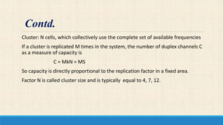
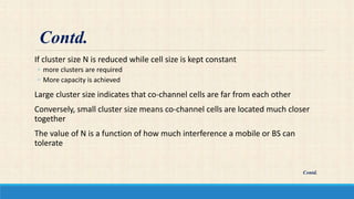
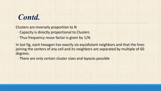
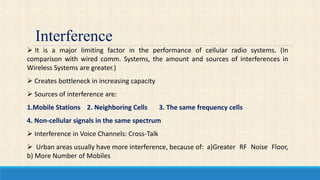
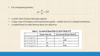
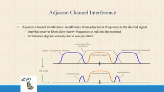
GANDHI INSTITUTE FOR TECHNOLOGY DEPT. OF ELECTRONICS AND
COMMUNICATION
ENGINEERING
Guided By:-
Pradipta Kumar Jena
Presented by:-
Pritish Mohapatra
Content
•Introduction
• What Is Cellular System?
• Cellular System Architecture
•Shape Of the Cell
•Cellular Geometric
INTRODUCTION
Cellular networks today are interference-limited due to the many users that
need to share the spectrum to achieve high-rate multimedia communication.
Cellular concept offered very high capacity in a limited spectrum allocation
without any major technological changes.
Interference is a major limiting factor in the performance of cellular radio
systems.
Interference in voice channel causes cross talk.
What is Cellular System?
•Wireless communication in which several small exchanges(cells)equipped
with low-power radio antennas are interconnected through a central
exchange.
•A cellular mobile communications system uses a large number of low-
power wireless transmitters to create cells—the basic geographic service
area of a wireless communications system.
Cellular System Architecture
Cells:-
A cell is the basic geographic unit of a cellular system.
Shape of the areas into which a coverage region is divided.
Cells are base stations transmitting over small geographic areas that are
represented as hexagons.
Each cell size varies depending on the landscape. Because of constraints
imposed by natural terrain and man-made structures
Clusters:-
A cluster is a group of cells No channels are reused within a cluster.
Shapes Of Cells
Square
Width of d-cell has four neighbours at distance d and four at distance d better
if all adjacent antennas equidistant
Hexagon
Provide equidistant antenna
Radius defined as radius of circum-circle
• Distance from centre to vertex equal length of size
Distance between centre cell radius R is R.
Not always precise hexagon.
• Topological hexagon
• Local signal propagation condition
• Location of antenna.
Three possible choices of shapes: square, equilateral
triangle and hexagon.
For a give distance between the center of a polygon and its
farthest perimeter points, the hexagon has the largest area
of the three
Thus by using hexagon geometry, the fewest number of cells
can cover a geographic region and it closely approximates
circle.
Contd.
Cellular Geometric
d
d
d
d
R
d
d
a)Square Pattern b)Hexagonal Pattern
Capacity of System
When using hexagon to model coverage areas
◦ Center-excited Cell: BS depicted as being either in the center of the cell
◦ Omni-directional antenna is used
◦ Edge-excited Cell: on three of the six cell vertices
◦ Sectored direction antenna is used
Consider a cellular system
◦ which has S duplex channels available for reuse.
◦ Each cell allocated group of k channels (k < S)
◦ S channels divided among N cells (unique and disjoint) then
S = kN Contd.
Cluster: N cells, which collectively use the complete set of available frequencies
If a cluster is replicated M times in the system, the number of duplex channels C
as a measure of capacity is
C = MkN = MS
So capacity is directly proportional to the replication factor in a fixed area.
Factor N is called cluster size and is typically equal to 4, 7, 12.
Contd.
If cluster size N is reduced while cell size is kept constant
◦ more clusters are required
◦ More capacity is achieved
Large cluster size indicates that co-channel cells are far from each other
Conversely, small cluster size means co-channel cells are located much closer
together
The value of N is a function of how much interference a mobile or BS can
tolerate
Contd.
Contd.
Clusters are inversely proportion to N
◦ Capacity is directly proportional to Clusters
◦ Thus frequency reuse factor is given by 1/N.
In last fig, each hexagon has exactly six equidistant neighbors and that the lines
joining the centers of any cell and its neighbors are separated by multiple of 60
degrees.
◦ There are only certain cluster sizes and layouts possible
Contd.
Interference Defined
-Unwanted signals
either entering your equipment
or
getting into equipment of other parties but generated by you.
Interference
 It is a major limiting factor in the performance of cellular radio systems. (In
comparison with wired comm. Systems, the amount and sources of interferences in
Wireless Systems are greater.)
 Creates bottleneck in increasing capacity
 Sources of interference are:
1.Mobile Stations 2. Neighboring Cells 3. The same frequency cells
4. Non-cellular signals in the same spectrum
 Interference in Voice Channels: Cross-Talk
 Urban areas usually have more interference, because of: a)Greater RF Noise Floor,
b) More Number of Mobiles
Interference Types
1. CO-CHANNEL INTERFERENCE
2. ADJACENT CHANNEL INTERFERENCE
Co-channel Interference and System Capacity
• Frequency reuse - there are several cells that use the same set of frequencies
– co-channel cells
– co-channel interference
• To reduce co-channel interference, co-channel cell must be separated by a minimum distance.
• When the size of the cell is approximately the same
– co-channel interference is independent of the transmitted power
– co-channel interference is a function of
• R: Radius of the cell
• D: distance to the center of the nearest co-channel cell
• Increasing the ratio Q=D/R, the interference is reduced.
• Q is called the co-channel reuse ratio
• For a hexagonal geometry
• A small value of Q provides large capacity
• A large value of Q improves the transmission quality - smaller level of co-channel interference
• A tradeoff must be made between these two objectives
N
R
D
Q 3
Adjacent Channel Interference
• Adjacent channel interference: interference from adjacent in frequency to the desired signal.
– Imperfect receiver filters allow nearby frequencies to leak into the passband
– Performance degrade seriously due to near-far effect.
desired signal
receiving filter
response
desired signal
interference
interference
signal on adjacent channelsignal on adjacent channel
FILTER
• Adjacent channel interference can be minimized through careful filtering
and channel assignment.
• Keep the frequency separation between each channel in a given cell as
large as possible
• A channel separation greater than six is needed to bring the adjacent
channel interference to an acceptable level.
continued
Power Control for Reducing Interference
• Ensure each mobile transmits the smallest power necessary to maintain a good quality link on
the reverse channel
– long battery life
– increase SIR
– solve the near-far problem
- RFI - Radio Frequency Interference
- - - Two or more signals competing for the same channel
- EMI - Electromagnetic Interference
- - - Appliances that are overloaded by strong EMI from
nearby RF sources
Interference : Flavours
- - - Disconnect components to localize problem area
- - - Check cable connections
- - - Check for grounded polarized plugs
- - - Ferrite cores around power cables
- - - Hipass filter on 300 ohm TV feedline
Solving RFI Problems
- Hard to track down appliance causing interference
- Microprocessors often generate EMI
- Enclose in grounded box
- Ferrite cores on cables
Solving EMI Problems
REFERENCE
Wireless Communication by T.S. RAPPAPORT
http://www.slideshare.net/ajal4u/interference-and-system-capacity
http://www.creativeworld9.com/2011/03/abstract-on-interference-cancellation.html
Presentation1
Presentation1

Presentation1

  • 1.
    GANDHI INSTITUTE FORTECHNOLOGY DEPT. OF ELECTRONICS AND COMMUNICATION ENGINEERING Guided By:- Pradipta Kumar Jena Presented by:- Pritish Mohapatra
  • 2.
    Content •Introduction • What IsCellular System? • Cellular System Architecture •Shape Of the Cell •Cellular Geometric
  • 3.
    INTRODUCTION Cellular networks todayare interference-limited due to the many users that need to share the spectrum to achieve high-rate multimedia communication. Cellular concept offered very high capacity in a limited spectrum allocation without any major technological changes. Interference is a major limiting factor in the performance of cellular radio systems. Interference in voice channel causes cross talk.
  • 4.
    What is CellularSystem? •Wireless communication in which several small exchanges(cells)equipped with low-power radio antennas are interconnected through a central exchange. •A cellular mobile communications system uses a large number of low- power wireless transmitters to create cells—the basic geographic service area of a wireless communications system.
  • 5.
    Cellular System Architecture Cells:- Acell is the basic geographic unit of a cellular system. Shape of the areas into which a coverage region is divided. Cells are base stations transmitting over small geographic areas that are represented as hexagons. Each cell size varies depending on the landscape. Because of constraints imposed by natural terrain and man-made structures Clusters:- A cluster is a group of cells No channels are reused within a cluster.
  • 6.
    Shapes Of Cells Square Widthof d-cell has four neighbours at distance d and four at distance d better if all adjacent antennas equidistant Hexagon Provide equidistant antenna Radius defined as radius of circum-circle • Distance from centre to vertex equal length of size Distance between centre cell radius R is R. Not always precise hexagon. • Topological hexagon • Local signal propagation condition • Location of antenna.
  • 7.
    Three possible choicesof shapes: square, equilateral triangle and hexagon. For a give distance between the center of a polygon and its farthest perimeter points, the hexagon has the largest area of the three Thus by using hexagon geometry, the fewest number of cells can cover a geographic region and it closely approximates circle. Contd.
  • 8.
  • 9.
    Capacity of System Whenusing hexagon to model coverage areas ◦ Center-excited Cell: BS depicted as being either in the center of the cell ◦ Omni-directional antenna is used ◦ Edge-excited Cell: on three of the six cell vertices ◦ Sectored direction antenna is used Consider a cellular system ◦ which has S duplex channels available for reuse. ◦ Each cell allocated group of k channels (k < S) ◦ S channels divided among N cells (unique and disjoint) then S = kN Contd.
  • 10.
    Cluster: N cells,which collectively use the complete set of available frequencies If a cluster is replicated M times in the system, the number of duplex channels C as a measure of capacity is C = MkN = MS So capacity is directly proportional to the replication factor in a fixed area. Factor N is called cluster size and is typically equal to 4, 7, 12. Contd.
  • 11.
    If cluster sizeN is reduced while cell size is kept constant ◦ more clusters are required ◦ More capacity is achieved Large cluster size indicates that co-channel cells are far from each other Conversely, small cluster size means co-channel cells are located much closer together The value of N is a function of how much interference a mobile or BS can tolerate Contd. Contd.
  • 12.
    Clusters are inverselyproportion to N ◦ Capacity is directly proportional to Clusters ◦ Thus frequency reuse factor is given by 1/N. In last fig, each hexagon has exactly six equidistant neighbors and that the lines joining the centers of any cell and its neighbors are separated by multiple of 60 degrees. ◦ There are only certain cluster sizes and layouts possible Contd.
  • 13.
    Interference Defined -Unwanted signals eitherentering your equipment or getting into equipment of other parties but generated by you.
  • 14.
    Interference  It isa major limiting factor in the performance of cellular radio systems. (In comparison with wired comm. Systems, the amount and sources of interferences in Wireless Systems are greater.)  Creates bottleneck in increasing capacity  Sources of interference are: 1.Mobile Stations 2. Neighboring Cells 3. The same frequency cells 4. Non-cellular signals in the same spectrum  Interference in Voice Channels: Cross-Talk  Urban areas usually have more interference, because of: a)Greater RF Noise Floor, b) More Number of Mobiles
  • 15.
    Interference Types 1. CO-CHANNELINTERFERENCE 2. ADJACENT CHANNEL INTERFERENCE
  • 16.
    Co-channel Interference andSystem Capacity • Frequency reuse - there are several cells that use the same set of frequencies – co-channel cells – co-channel interference • To reduce co-channel interference, co-channel cell must be separated by a minimum distance. • When the size of the cell is approximately the same – co-channel interference is independent of the transmitted power – co-channel interference is a function of • R: Radius of the cell • D: distance to the center of the nearest co-channel cell • Increasing the ratio Q=D/R, the interference is reduced. • Q is called the co-channel reuse ratio
  • 17.
    • For ahexagonal geometry • A small value of Q provides large capacity • A large value of Q improves the transmission quality - smaller level of co-channel interference • A tradeoff must be made between these two objectives N R D Q 3
  • 18.
    Adjacent Channel Interference •Adjacent channel interference: interference from adjacent in frequency to the desired signal. – Imperfect receiver filters allow nearby frequencies to leak into the passband – Performance degrade seriously due to near-far effect. desired signal receiving filter response desired signal interference interference signal on adjacent channelsignal on adjacent channel FILTER
  • 19.
    • Adjacent channelinterference can be minimized through careful filtering and channel assignment. • Keep the frequency separation between each channel in a given cell as large as possible • A channel separation greater than six is needed to bring the adjacent channel interference to an acceptable level. continued
  • 20.
    Power Control forReducing Interference • Ensure each mobile transmits the smallest power necessary to maintain a good quality link on the reverse channel – long battery life – increase SIR – solve the near-far problem
  • 21.
    - RFI -Radio Frequency Interference - - - Two or more signals competing for the same channel - EMI - Electromagnetic Interference - - - Appliances that are overloaded by strong EMI from nearby RF sources Interference : Flavours
  • 22.
    - - -Disconnect components to localize problem area - - - Check cable connections - - - Check for grounded polarized plugs - - - Ferrite cores around power cables - - - Hipass filter on 300 ohm TV feedline Solving RFI Problems
  • 23.
    - Hard totrack down appliance causing interference - Microprocessors often generate EMI - Enclose in grounded box - Ferrite cores on cables Solving EMI Problems
  • 24.
    REFERENCE Wireless Communication byT.S. RAPPAPORT http://www.slideshare.net/ajal4u/interference-and-system-capacity http://www.creativeworld9.com/2011/03/abstract-on-interference-cancellation.html