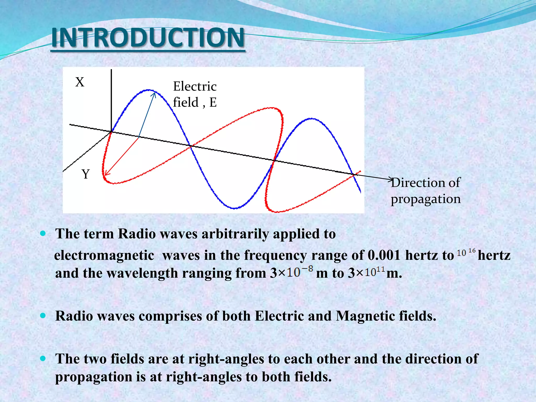
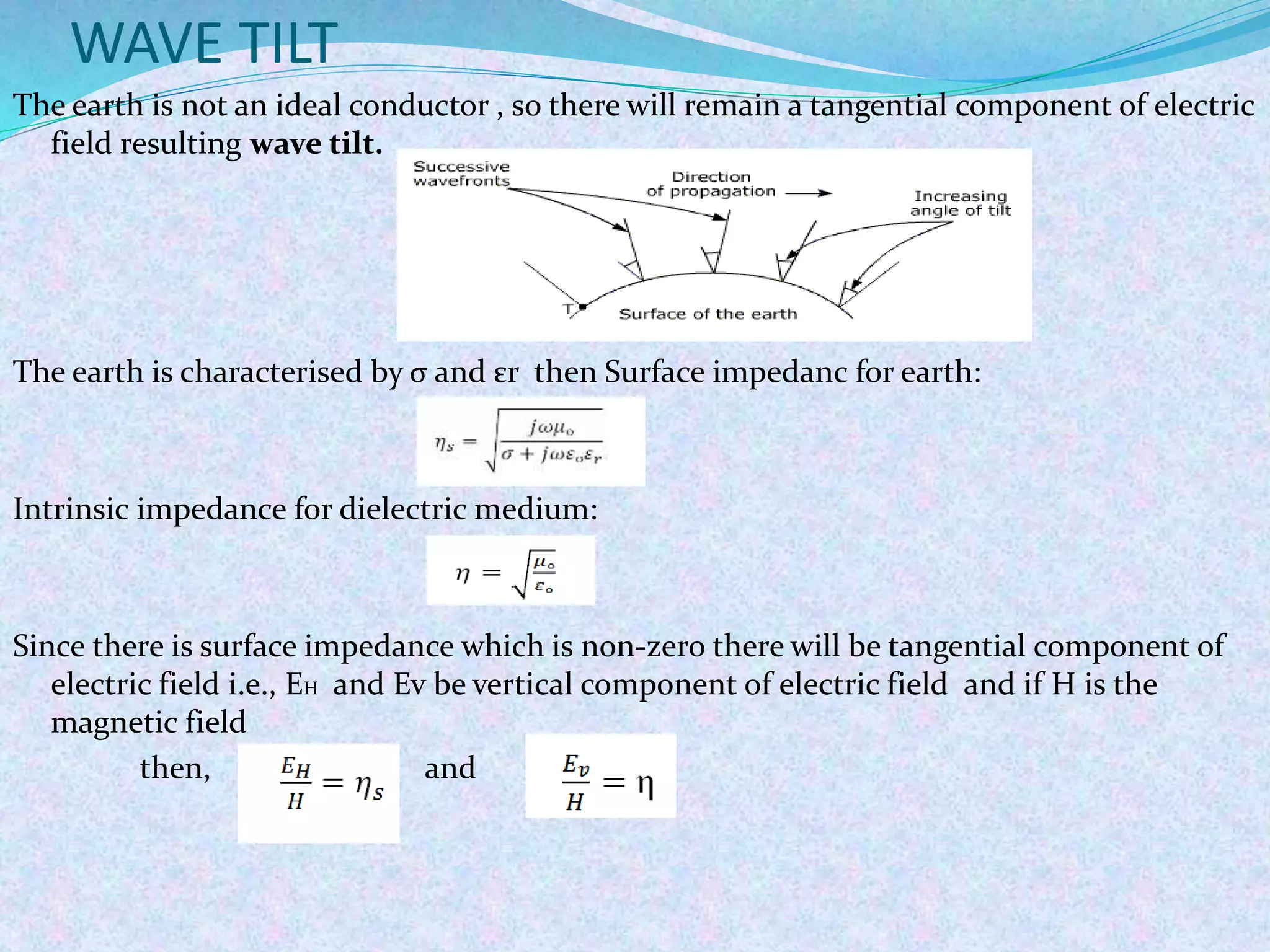
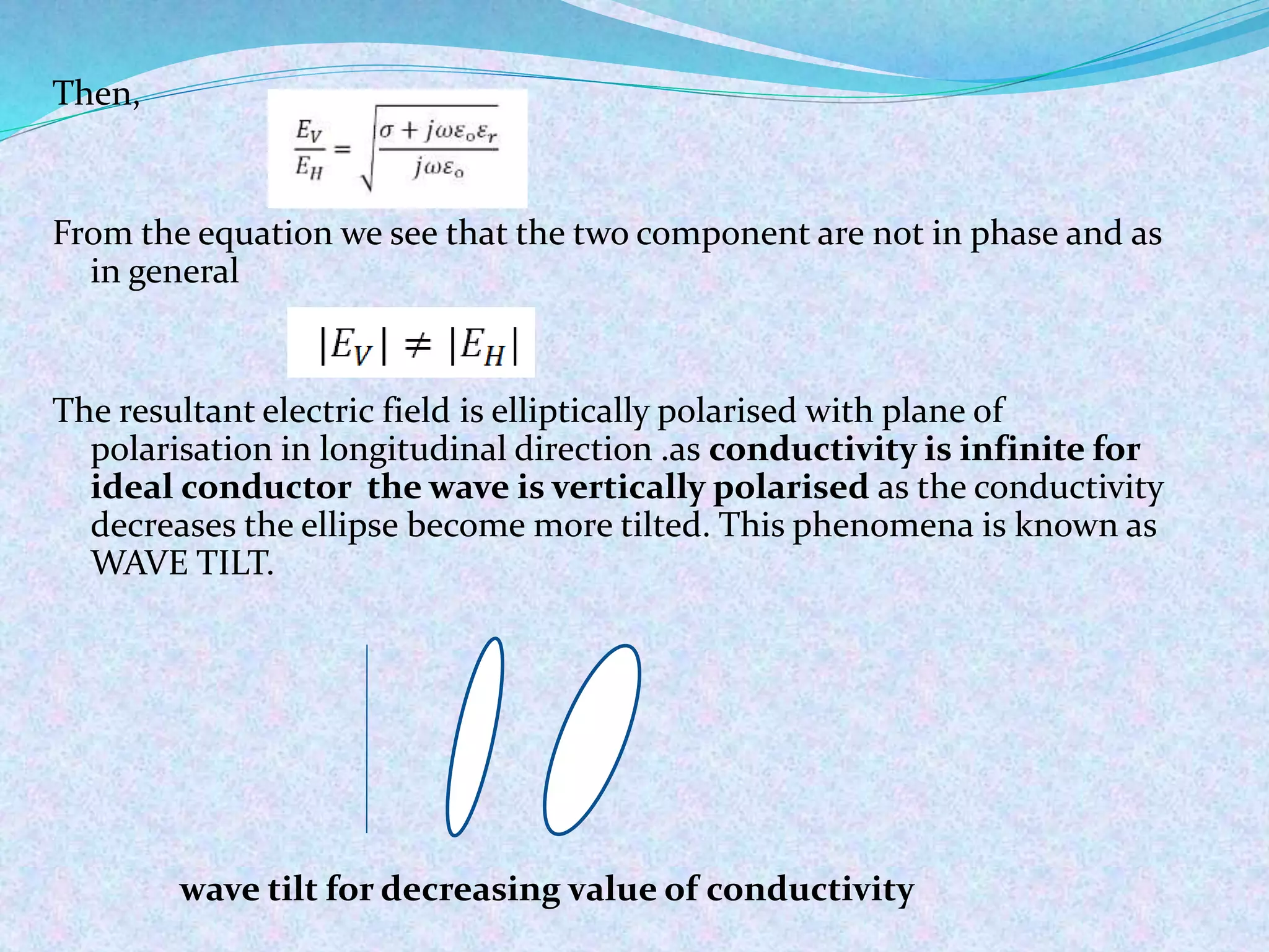
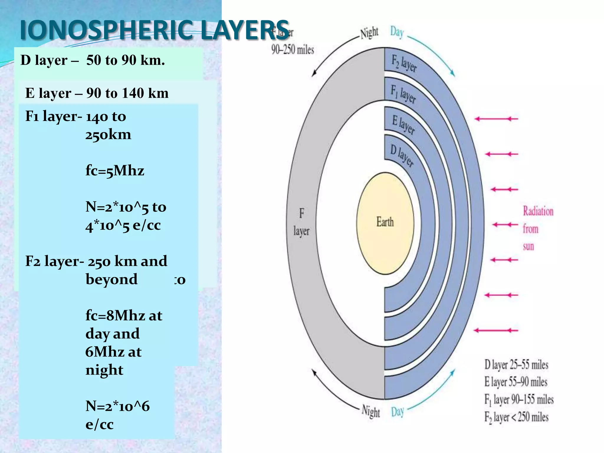
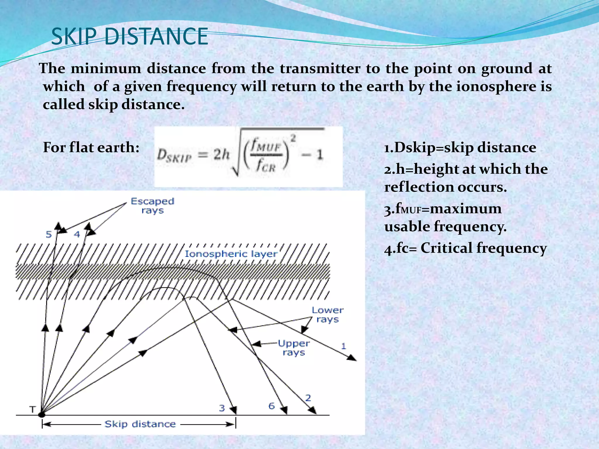
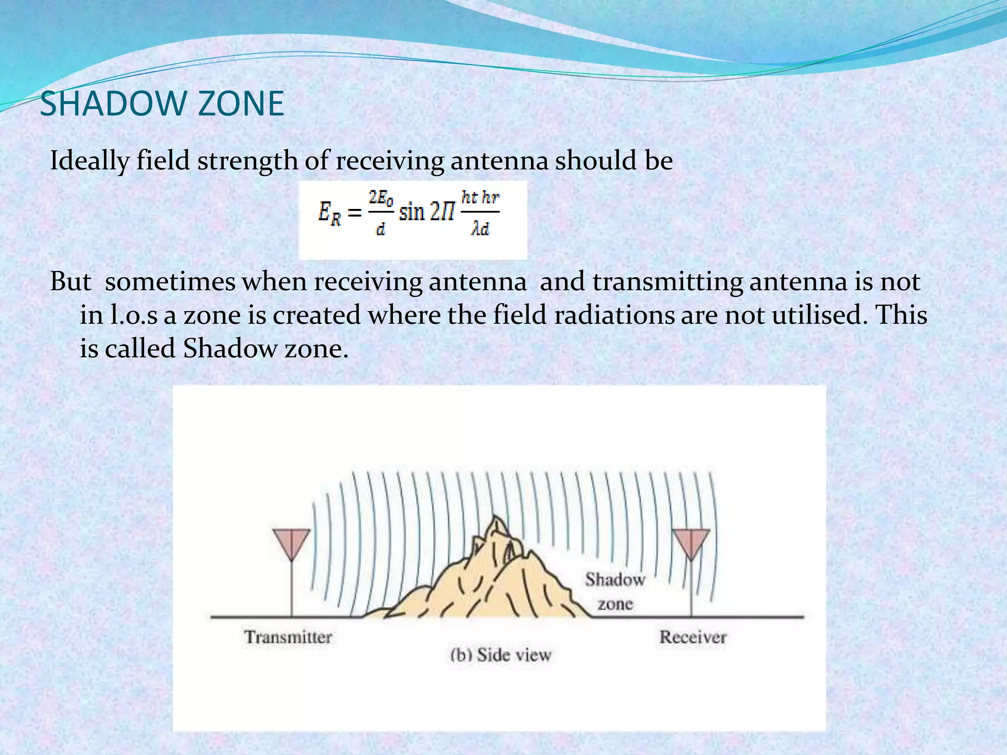
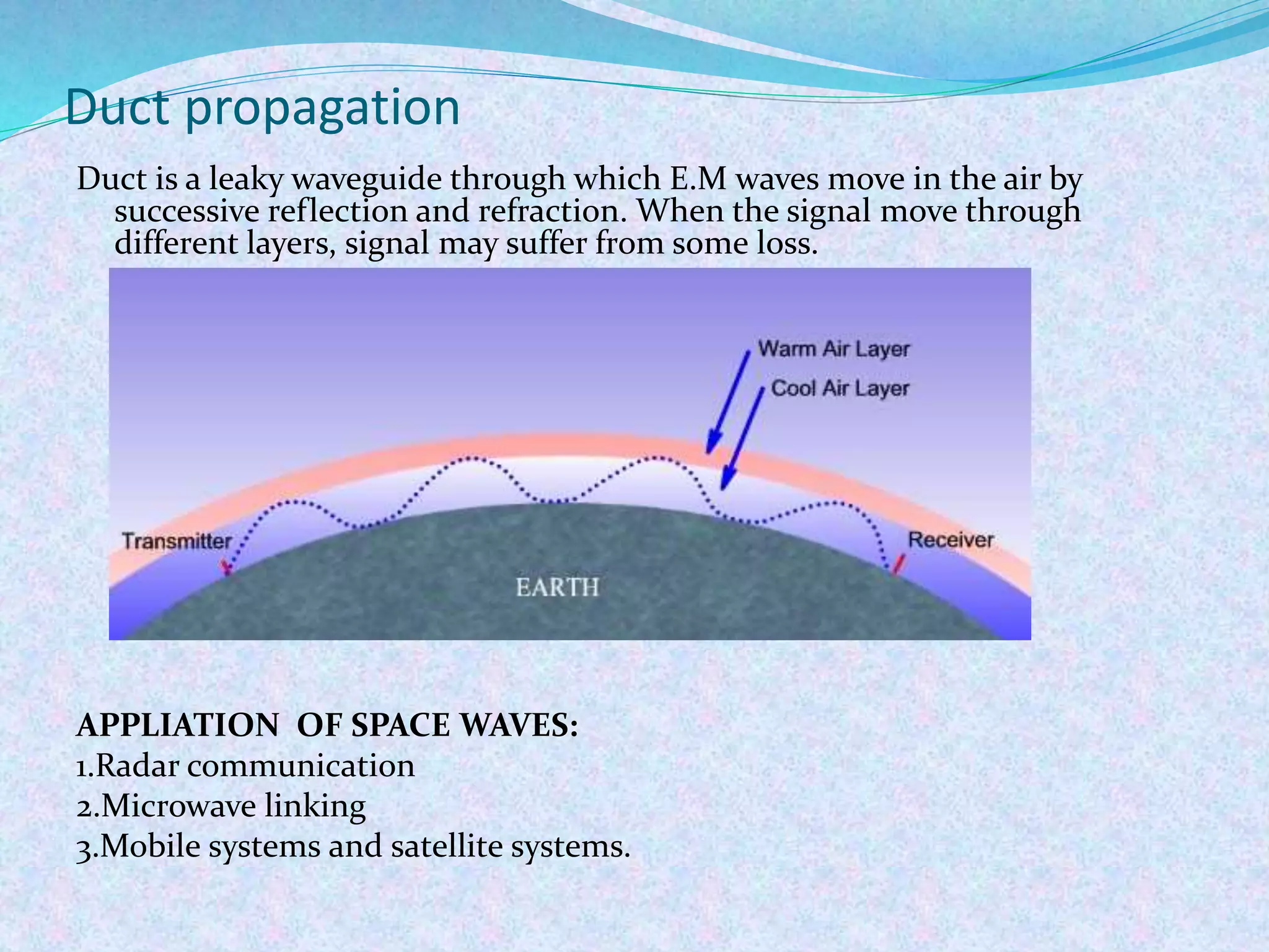
SlideShare a Scribd company logo
Submitted by,
Ritika De
11900313040
Under the guidance of,
Associate Prof Dr. Sudipta Chattopadhyay
CONTENTS
Introduction
Radio wave propagation
Classification of radio waves
Different modes of propagation
Ground Wave propagation
Sky wave propagation
Space wave propagation
Conclusion
Bibilography
INTRODUCTION
 The term Radio waves arbitrarily applied to
electromagnetic waves in the frequency range of 0.001 hertz to hertz
and the wavelength ranging from 3× m to 3× m.
 Radio waves comprises of both Electric and Magnetic fields.
 The two fields are at right-angles to each other and the direction of
propagation is at right-angles to both fields.
X
Y
Electric
field , E
Direction of
propagation
RADIO WAVE PROPAGATION
 Radio Waves propagate outward from an antenna , at the speed
of light. The exact nature of these waves is determined by the
transmission medium. i.e., In free space they travel in straight
lines , whereas in the atmosphere they generally travel in curved
path.
 In a unguided medium, radio waves propagate in TEM mode
while in confined or guided medium radio waves do not
propagate in the TEM mode but in TM or TE mode.
 Radio waves can be reflected and refracted in a manner similar
to light . They are effected by ground terrain, atmosphere and
other objects.
CLASSIFICATION OF RADIO WAVES
Based on Frequency:
DIFFERENT MODES OF PROPAGATION
Radio waves
Ground waves
Space waves or Line
of Sight waves
Direct waves
Ground reflected waves
Sky waves
MODES OF PROPAGATION FREQUENCY APPLICATION
1. Ground waves VLF
LF
MF
1.Submarine Communication
2.AM ,FM and television
broadcasting
2. Space or line of sight waves HF
VHF
UHF
1.Satellite communication
2.Mobile communication
3. Sky waves 2Mhz-30Mhz 1.Microwave link
2.Radar communication
GROUND WAVE PROPAGATION
 It propagates from transmitter to receiver by gliding over the surface of the
earth in which both antennas are close to the surface of the earth. It follows
the curvature of the earth.
 Earth is assumed to be an ideal conductor ,EM waves cannot penetrate ideal
conductor only exist in dielectric medium above conducting surface that’s
why ground wave propagation is possible.
 The Ground waves are traverse in nature. Horizontal polarised antennas are
not preferred as the horizontal component of the electric field in contact with
the earth is short circuited by the earth.
WAVE TILT
The earth is not an ideal conductor , so there will remain a tangential component of electric
field resulting wave tilt.
The earth is characterised by σ and εr then Surface impedanc for earth:
Intrinsic impedance for dielectric medium:
Since there is surface impedance which is non-zero there will be tangential component of
electric field i.e., EH and Ev be vertical component of electric field and if H is the
magnetic field
then, and
Then,
From the equation we see that the two component are not in phase and as
in general
The resultant electric field is elliptically polarised with plane of
polarisation in longitudinal direction .as conductivity is infinite for
ideal conductor the wave is vertically polarised as the conductivity
decreases the ellipse become more tilted. This phenomena is known as
WAVE TILT.
wave tilt for decreasing value of conductivity
SKY WAVE PROPAGATION
• The sky waves are reflected from ionized layer of atmosphere back down to
the earth surface and is useful for very long range distance communication
• They can travel a number of layers, back and forth between ionosphere and
earth’s surface.
• The sky wave, often called the ionospheric wave.
11
D layer – 50 to 90 km.
Disappears at
night.
N=400e/cc
fc=180KHz
Mainly reflects
ULF and LF
E layer – 90 to 140 km
Disappears at
night.
N=2* 10^5 e/cc
fc=4mhz
IONOSPHERIC LAYERS
Sporadic E layer:
Temporary layer
Summer time
thin layer of intense
ionisation clouds.
reflect frequency up to
224 MHz
90-130 km
F1 layer- 140 to
250km
fc=5Mhz
N=2*10^5 to
4*10^5 e/cc
F2 layer- 250 km and
beyond
fc=8Mhz at
day and
6Mhz at
night
N=2*10^6
e/cc
CRITICAL FREQUENCY
Critical frequency (fc) for given layer is defined as the highest frequency
of wave that will be returned to the earth by that layer having been
beamed normal ly at it.
Nmax = maximum ionisation density i.e., no. of electrons per unit
volume .
MUF is defined as the highest frequency at which it is reflected by the ionospheric
layer at the angle of incidence other than normal incidence.
 MUF depends on time ,day ,distance
direction and solar activity.
 MUF is the highest frequency that can be
used by sky waves.
MAXIMUM USABLE FREQUENCY(MUF)
SKIP DISTANCE
The minimum distance from the transmitter to the point on ground at
which of a given frequency will return to the earth by the ionosphere is
called skip distance.
For flat earth: 1.Dskip=skip distance
2.h=height at which the
reflection occurs.
3.fMUF=maximum
usable frequency.
4.fc= Critical frequency
Dskip
h
i
T R
ionosphere
VIRTUAL HEIGHT
The virtual height of an ionospheric layer is the equivalent altitude
of a reflection that would produce the same effect as the actual
refraction.
c=speed of light=3×10⁸
T=round trip time
APPLICATION OF SKY WAVES:
1.Satellite Communication
2. Mobile communication
FADING:
 Fading is defined as the fluctuation in the received signal strength at the
receiver or a random variation in the received signal.
 Fading may be classified in terms of duration of variation in signal
strength as :
1) Rapid Fluctuations
2)Short Term Fluctuations
3)Long term Fluctuations
 The various types of fading are as follows:
 Selective Fading: At high frequency.
 Interference Fading
 Absorption Fading
 Polarization Fading
 Skip Fading
SPACE WAVE PROPAGATION(line of sight)
 These waves occur within the lower 20 km of the atmosphere i.e.
troposphere .
 In this mode of wave propagation electromagnetic waves after
transmitted from transmitting antenna reaches the receiving antenna
either directly or after reflection from earth’s surface and tropospheric
region. i.e., direct wave and ground reflected wave or indirect wave.
SHADOW ZONE
Ideally field strength of receiving antenna should be
But sometimes when receiving antenna and transmitting antenna is not
in l.o.s a zone is created where the field radiations are not utilised. This
is called Shadow zone.
RADIO HORIZON
The radio horizon of an antenna is defined as the distant points locus at which
antenna’s direct ray become tangential to planetary surface.
a
Let h1=transmitting antenna’s
height
h2= receiving antenna’s height
a= radius of the earth
Duct propagation
Duct is a leaky waveguide through which E.M waves move in the air by
successive reflection and refraction. When the signal move through
different layers, signal may suffer from some loss.
APPLIATION OF SPACE WAVES:
1.Radar communication
2.Microwave linking
3.Mobile systems and satellite systems.
CONCLUSION
Radio wave signals are mainly used for communication purpose. Starting
from transmission of television broadcast signals to the communication
with aircrafts, every mode of communication and transportation is
dependent on signals transmitted in radio wave frequency .The main
objective of radio wave propagation is to transmit signals securely
without any error. Mobile phones use radio signals for communication
purpose. It can be concluded that Radio wave Propagation is an
Important branch of Communication studies.
BIBILOGRAPHY
 https://en.wikibooks.org/wiki/Communication_Systems/Wave_Propag
ation
 http://wikipedia.org/radio wave propagation.
 Electronic communications by DENNIS ROODY ,JOHN COOLEN
 www.radioelectronics.com.
QUERIES???

More Related Content

What's hot

FUNDAMENTAL PARAMETERS OF ANTENNA
FUNDAMENTAL PARAMETERS OF ANTENNAFUNDAMENTAL PARAMETERS OF ANTENNA
FUNDAMENTAL PARAMETERS OF ANTENNA
Engr KALIM ULLAH KHAN
 
Critical frequency
Critical frequencyCritical frequency
Critical frequency
Gautam Saxena
 
radio-wave-propagation-presentations
radio-wave-propagation-presentationsradio-wave-propagation-presentations
radio-wave-propagation-presentations
ATTO RATHORE
 
Cw and fm cw radar
Cw and fm cw radarCw and fm cw radar
Cw and fm cw radar
Vijendrasingh Rathor
 
Antenna Basics
Antenna BasicsAntenna Basics
Antenna Basics
Md Mustafizur Rahman
 
Rectangular waveguides
Rectangular waveguidesRectangular waveguides
Rectangular waveguides
khan yaseen
 
radio-wave-propagation
radio-wave-propagationradio-wave-propagation
radio-wave-propagation
ATTO RATHORE
 
Antennas wave and propagation
 Antennas wave and propagation Antennas wave and propagation
Antennas wave and propagation
Isha Negi
 
EC6602-Antenna fundamentals new
EC6602-Antenna fundamentals new EC6602-Antenna fundamentals new
EC6602-Antenna fundamentals new
krishnamrm
 
Radar Systems -Unit- I : Radar Equation
Radar Systems -Unit- I : Radar Equation Radar Systems -Unit- I : Radar Equation
Radar Systems -Unit- I : Radar Equation
VenkataRatnam14
 
wave-guides
wave-guideswave-guides
wave-guides
ATTO RATHORE
 
Antennas slideshare part 2
Antennas slideshare part 2Antennas slideshare part 2
Antennas slideshare part 2
Muthumanickam
 
Antennas and their types
Antennas and their typesAntennas and their types
Antennas and their types
venati munishareddy
 
Mobile satellite communication
Mobile satellite communicationMobile satellite communication
Mobile satellite communication
Tanjarul Islam Mishu
 
RF and Microwave Engineering
RF  and Microwave EngineeringRF  and Microwave Engineering
RF and Microwave Engineering
srirenga
 
Antenna slide
Antenna slideAntenna slide
Antenna slide
Shahidul Islam Himel
 
wave propagation
wave propagationwave propagation
wave propagation
ATTO RATHORE
 
Microwave propagation in ferrites 23
Microwave propagation in ferrites 23Microwave propagation in ferrites 23
Microwave propagation in ferrites 23
HIMANSHU DIWAKAR
 

What's hot (20)

FUNDAMENTAL PARAMETERS OF ANTENNA
FUNDAMENTAL PARAMETERS OF ANTENNAFUNDAMENTAL PARAMETERS OF ANTENNA
FUNDAMENTAL PARAMETERS OF ANTENNA
 
Critical frequency
Critical frequencyCritical frequency
Critical frequency
 
radio-wave-propagation-presentations
radio-wave-propagation-presentationsradio-wave-propagation-presentations
radio-wave-propagation-presentations
 
Cw and fm cw radar
Cw and fm cw radarCw and fm cw radar
Cw and fm cw radar
 
Antenna Basics
Antenna BasicsAntenna Basics
Antenna Basics
 
Rectangular waveguides
Rectangular waveguidesRectangular waveguides
Rectangular waveguides
 
radio-wave-propagation
radio-wave-propagationradio-wave-propagation
radio-wave-propagation
 
Antennas wave and propagation
 Antennas wave and propagation Antennas wave and propagation
Antennas wave and propagation
 
EC6602-Antenna fundamentals new
EC6602-Antenna fundamentals new EC6602-Antenna fundamentals new
EC6602-Antenna fundamentals new
 
Radar Systems -Unit- I : Radar Equation
Radar Systems -Unit- I : Radar Equation Radar Systems -Unit- I : Radar Equation
Radar Systems -Unit- I : Radar Equation
 
wave-guides
wave-guideswave-guides
wave-guides
 
Antennas slideshare part 2
Antennas slideshare part 2Antennas slideshare part 2
Antennas slideshare part 2
 
Antennas and their types
Antennas and their typesAntennas and their types
Antennas and their types
 
Mobile satellite communication
Mobile satellite communicationMobile satellite communication
Mobile satellite communication
 
RF and Microwave Engineering
RF  and Microwave EngineeringRF  and Microwave Engineering
RF and Microwave Engineering
 
Antenna slide
Antenna slideAntenna slide
Antenna slide
 
Antenna system
Antenna systemAntenna system
Antenna system
 
Antenna
AntennaAntenna
Antenna
 
wave propagation
wave propagationwave propagation
wave propagation
 
Microwave propagation in ferrites 23
Microwave propagation in ferrites 23Microwave propagation in ferrites 23
Microwave propagation in ferrites 23
 

Similar to Radio Wave propagation

Communication - Space Communication Class 12 Part-5
Communication - Space Communication Class 12 Part-5Communication - Space Communication Class 12 Part-5
Communication - Space Communication Class 12 Part-5Self-employed
 
radio propagation
radio propagationradio propagation
radio propagation
ATTO RATHORE
 
RWP TOTAL.pptx
RWP TOTAL.pptxRWP TOTAL.pptx
RWP TOTAL.pptx
babu493477
 
Srikarsh Awp
Srikarsh AwpSrikarsh Awp
Srikarsh Awp
Kolanu Reddy
 
SECX1029-UNIT-4.PDF
SECX1029-UNIT-4.PDFSECX1029-UNIT-4.PDF
مهم جدا هوائيات.pptx
مهم جدا هوائيات.pptxمهم جدا هوائيات.pptx
مهم جدا هوائيات.pptx
tahaniali27
 
wave propagationn
wave propagationnwave propagationn
wave propagationn
ATTO RATHORE
 
Fundamentals of EM Waves
Fundamentals of EM WavesFundamentals of EM Waves
Fundamentals of EM WavesAjab Tanwar
 
Lesson 7 propagation
Lesson 7 propagationLesson 7 propagation
Lesson 7 propagation
Moises Ngomane
 
8th sem notes ppt.pptx
8th sem notes ppt.pptx8th sem notes ppt.pptx
8th sem notes ppt.pptx
DipayanDasgupta11
 
Line of-sight propagation by najmul hoque munshi
Line of-sight propagation by najmul hoque munshiLine of-sight propagation by najmul hoque munshi
Line of-sight propagation by najmul hoque munshi
NajmulHoqueMunshi
 
6_2021_09_15!09_53_01_PM.pptx
6_2021_09_15!09_53_01_PM.pptx6_2021_09_15!09_53_01_PM.pptx
6_2021_09_15!09_53_01_PM.pptx
shubhamonlyjha8448
 
basics of Radio Wave Propagation (2).pptx
basics of Radio Wave Propagation (2).pptxbasics of Radio Wave Propagation (2).pptx
basics of Radio Wave Propagation (2).pptx
IdrisJeffreyManguera
 
microwave-fundamentals
microwave-fundamentalsmicrowave-fundamentals
microwave-fundamentals
ATTO RATHORE
 
Electromagnetic Wave propagation, Electromagnetic
Electromagnetic Wave propagation, ElectromagneticElectromagnetic Wave propagation, Electromagnetic
Electromagnetic Wave propagation, Electromagnetic
Muhammad Ibrahim
 
E5.1 commn unit 2 md
E5.1 commn unit 2 mdE5.1 commn unit 2 md
E5.1 commn unit 2 md
MahiboobAliMulla
 
Radio Wave Propagation
Radio Wave PropagationRadio Wave Propagation
Radio Wave Propagation
Erica May Reyes
 
WAVE PROPAGATION - Copy.pptx
WAVE PROPAGATION - Copy.pptxWAVE PROPAGATION - Copy.pptx
WAVE PROPAGATION - Copy.pptx
Satendarchauhan
 
Chap 02 antenna & wave propagation
Chap 02 antenna & wave propagation Chap 02 antenna & wave propagation
Chap 02 antenna & wave propagation
EngkaderAMuse
 

Similar to Radio Wave propagation (20)

Communication - Space Communication Class 12 Part-5
Communication - Space Communication Class 12 Part-5Communication - Space Communication Class 12 Part-5
Communication - Space Communication Class 12 Part-5
 
radio propagation
radio propagationradio propagation
radio propagation
 
RWP TOTAL.pptx
RWP TOTAL.pptxRWP TOTAL.pptx
RWP TOTAL.pptx
 
Srikarsh Awp
Srikarsh AwpSrikarsh Awp
Srikarsh Awp
 
SECX1029-UNIT-4.PDF
SECX1029-UNIT-4.PDFSECX1029-UNIT-4.PDF
SECX1029-UNIT-4.PDF
 
مهم جدا هوائيات.pptx
مهم جدا هوائيات.pptxمهم جدا هوائيات.pptx
مهم جدا هوائيات.pptx
 
wave propagationn
wave propagationnwave propagationn
wave propagationn
 
Fundamentals of EM Waves
Fundamentals of EM WavesFundamentals of EM Waves
Fundamentals of EM Waves
 
Lesson 7 propagation
Lesson 7 propagationLesson 7 propagation
Lesson 7 propagation
 
8th sem notes ppt.pptx
8th sem notes ppt.pptx8th sem notes ppt.pptx
8th sem notes ppt.pptx
 
Line of-sight propagation by najmul hoque munshi
Line of-sight propagation by najmul hoque munshiLine of-sight propagation by najmul hoque munshi
Line of-sight propagation by najmul hoque munshi
 
6_2021_09_15!09_53_01_PM.pptx
6_2021_09_15!09_53_01_PM.pptx6_2021_09_15!09_53_01_PM.pptx
6_2021_09_15!09_53_01_PM.pptx
 
Radio waves
Radio wavesRadio waves
Radio waves
 
basics of Radio Wave Propagation (2).pptx
basics of Radio Wave Propagation (2).pptxbasics of Radio Wave Propagation (2).pptx
basics of Radio Wave Propagation (2).pptx
 
microwave-fundamentals
microwave-fundamentalsmicrowave-fundamentals
microwave-fundamentals
 
Electromagnetic Wave propagation, Electromagnetic
Electromagnetic Wave propagation, ElectromagneticElectromagnetic Wave propagation, Electromagnetic
Electromagnetic Wave propagation, Electromagnetic
 
E5.1 commn unit 2 md
E5.1 commn unit 2 mdE5.1 commn unit 2 md
E5.1 commn unit 2 md
 
Radio Wave Propagation
Radio Wave PropagationRadio Wave Propagation
Radio Wave Propagation
 
WAVE PROPAGATION - Copy.pptx
WAVE PROPAGATION - Copy.pptxWAVE PROPAGATION - Copy.pptx
WAVE PROPAGATION - Copy.pptx
 
Chap 02 antenna & wave propagation
Chap 02 antenna & wave propagation Chap 02 antenna & wave propagation
Chap 02 antenna & wave propagation
 

Recently uploaded

Standard Reomte Control Interface - Neometrix
Standard Reomte Control Interface - NeometrixStandard Reomte Control Interface - Neometrix
Standard Reomte Control Interface - Neometrix
Neometrix_Engineering_Pvt_Ltd
 
在线办理(ANU毕业证书)澳洲国立大学毕业证录取通知书一模一样
在线办理(ANU毕业证书)澳洲国立大学毕业证录取通知书一模一样在线办理(ANU毕业证书)澳洲国立大学毕业证录取通知书一模一样
在线办理(ANU毕业证书)澳洲国立大学毕业证录取通知书一模一样
obonagu
 
The Benefits and Techniques of Trenchless Pipe Repair.pdf
The Benefits and Techniques of Trenchless Pipe Repair.pdfThe Benefits and Techniques of Trenchless Pipe Repair.pdf
The Benefits and Techniques of Trenchless Pipe Repair.pdf
Pipe Restoration Solutions
 
Investor-Presentation-Q1FY2024 investor presentation document.pptx
Investor-Presentation-Q1FY2024 investor presentation document.pptxInvestor-Presentation-Q1FY2024 investor presentation document.pptx
Investor-Presentation-Q1FY2024 investor presentation document.pptx
AmarGB2
 
CME397 Surface Engineering- Professional Elective
CME397 Surface Engineering- Professional ElectiveCME397 Surface Engineering- Professional Elective
CME397 Surface Engineering- Professional Elective
karthi keyan
 
CFD Simulation of By-pass Flow in a HRSG module by R&R Consult.pptx
CFD Simulation of By-pass Flow in a HRSG module by R&R Consult.pptxCFD Simulation of By-pass Flow in a HRSG module by R&R Consult.pptx
CFD Simulation of By-pass Flow in a HRSG module by R&R Consult.pptx
R&R Consult
 
MCQ Soil mechanics questions (Soil shear strength).pdf
MCQ Soil mechanics questions (Soil shear strength).pdfMCQ Soil mechanics questions (Soil shear strength).pdf
MCQ Soil mechanics questions (Soil shear strength).pdf
Osamah Alsalih
 
HYDROPOWER - Hydroelectric power generation
HYDROPOWER - Hydroelectric power generationHYDROPOWER - Hydroelectric power generation
HYDROPOWER - Hydroelectric power generation
Robbie Edward Sayers
 
Runway Orientation Based on the Wind Rose Diagram.pptx
Runway Orientation Based on the Wind Rose Diagram.pptxRunway Orientation Based on the Wind Rose Diagram.pptx
Runway Orientation Based on the Wind Rose Diagram.pptx
SupreethSP4
 
AP LAB PPT.pdf ap lab ppt no title specific
AP LAB PPT.pdf ap lab ppt no title specificAP LAB PPT.pdf ap lab ppt no title specific
AP LAB PPT.pdf ap lab ppt no title specific
BrazilAccount1
 
H.Seo, ICLR 2024, MLILAB, KAIST AI.pdf
H.Seo,  ICLR 2024, MLILAB,  KAIST AI.pdfH.Seo,  ICLR 2024, MLILAB,  KAIST AI.pdf
H.Seo, ICLR 2024, MLILAB, KAIST AI.pdf
MLILAB
 
Design and Analysis of Algorithms-DP,Backtracking,Graphs,B&B
Design and Analysis of Algorithms-DP,Backtracking,Graphs,B&BDesign and Analysis of Algorithms-DP,Backtracking,Graphs,B&B
Design and Analysis of Algorithms-DP,Backtracking,Graphs,B&B
Sreedhar Chowdam
 
Architectural Portfolio Sean Lockwood
Architectural Portfolio Sean LockwoodArchitectural Portfolio Sean Lockwood
Architectural Portfolio Sean Lockwood
seandesed
 
road safety engineering r s e unit 3.pdf
road safety engineering  r s e unit 3.pdfroad safety engineering  r s e unit 3.pdf
road safety engineering r s e unit 3.pdf
VENKATESHvenky89705
 
Hierarchical Digital Twin of a Naval Power System
Hierarchical Digital Twin of a Naval Power SystemHierarchical Digital Twin of a Naval Power System
Hierarchical Digital Twin of a Naval Power System
Kerry Sado
 
ethical hacking in wireless-hacking1.ppt
ethical hacking in wireless-hacking1.pptethical hacking in wireless-hacking1.ppt
ethical hacking in wireless-hacking1.ppt
Jayaprasanna4
 
Student information management system project report ii.pdf
Student information management system project report ii.pdfStudent information management system project report ii.pdf
Student information management system project report ii.pdf
Kamal Acharya
 
Top 10 Oil and Gas Projects in Saudi Arabia 2024.pdf
Top 10 Oil and Gas Projects in Saudi Arabia 2024.pdfTop 10 Oil and Gas Projects in Saudi Arabia 2024.pdf
Top 10 Oil and Gas Projects in Saudi Arabia 2024.pdf
Teleport Manpower Consultant
 
一比一原版(IIT毕业证)伊利诺伊理工大学毕业证成绩单专业办理
一比一原版(IIT毕业证)伊利诺伊理工大学毕业证成绩单专业办理一比一原版(IIT毕业证)伊利诺伊理工大学毕业证成绩单专业办理
一比一原版(IIT毕业证)伊利诺伊理工大学毕业证成绩单专业办理
zwunae
 
Pile Foundation by Venkatesh Taduvai (Sub Geotechnical Engineering II)-conver...
Pile Foundation by Venkatesh Taduvai (Sub Geotechnical Engineering II)-conver...Pile Foundation by Venkatesh Taduvai (Sub Geotechnical Engineering II)-conver...
Pile Foundation by Venkatesh Taduvai (Sub Geotechnical Engineering II)-conver...
AJAYKUMARPUND1
 

Recently uploaded (20)

Standard Reomte Control Interface - Neometrix
Standard Reomte Control Interface - NeometrixStandard Reomte Control Interface - Neometrix
Standard Reomte Control Interface - Neometrix
 
在线办理(ANU毕业证书)澳洲国立大学毕业证录取通知书一模一样
在线办理(ANU毕业证书)澳洲国立大学毕业证录取通知书一模一样在线办理(ANU毕业证书)澳洲国立大学毕业证录取通知书一模一样
在线办理(ANU毕业证书)澳洲国立大学毕业证录取通知书一模一样
 
The Benefits and Techniques of Trenchless Pipe Repair.pdf
The Benefits and Techniques of Trenchless Pipe Repair.pdfThe Benefits and Techniques of Trenchless Pipe Repair.pdf
The Benefits and Techniques of Trenchless Pipe Repair.pdf
 
Investor-Presentation-Q1FY2024 investor presentation document.pptx
Investor-Presentation-Q1FY2024 investor presentation document.pptxInvestor-Presentation-Q1FY2024 investor presentation document.pptx
Investor-Presentation-Q1FY2024 investor presentation document.pptx
 
CME397 Surface Engineering- Professional Elective
CME397 Surface Engineering- Professional ElectiveCME397 Surface Engineering- Professional Elective
CME397 Surface Engineering- Professional Elective
 
CFD Simulation of By-pass Flow in a HRSG module by R&R Consult.pptx
CFD Simulation of By-pass Flow in a HRSG module by R&R Consult.pptxCFD Simulation of By-pass Flow in a HRSG module by R&R Consult.pptx
CFD Simulation of By-pass Flow in a HRSG module by R&R Consult.pptx
 
MCQ Soil mechanics questions (Soil shear strength).pdf
MCQ Soil mechanics questions (Soil shear strength).pdfMCQ Soil mechanics questions (Soil shear strength).pdf
MCQ Soil mechanics questions (Soil shear strength).pdf
 
HYDROPOWER - Hydroelectric power generation
HYDROPOWER - Hydroelectric power generationHYDROPOWER - Hydroelectric power generation
HYDROPOWER - Hydroelectric power generation
 
Runway Orientation Based on the Wind Rose Diagram.pptx
Runway Orientation Based on the Wind Rose Diagram.pptxRunway Orientation Based on the Wind Rose Diagram.pptx
Runway Orientation Based on the Wind Rose Diagram.pptx
 
AP LAB PPT.pdf ap lab ppt no title specific
AP LAB PPT.pdf ap lab ppt no title specificAP LAB PPT.pdf ap lab ppt no title specific
AP LAB PPT.pdf ap lab ppt no title specific
 
H.Seo, ICLR 2024, MLILAB, KAIST AI.pdf
H.Seo,  ICLR 2024, MLILAB,  KAIST AI.pdfH.Seo,  ICLR 2024, MLILAB,  KAIST AI.pdf
H.Seo, ICLR 2024, MLILAB, KAIST AI.pdf
 
Design and Analysis of Algorithms-DP,Backtracking,Graphs,B&B
Design and Analysis of Algorithms-DP,Backtracking,Graphs,B&BDesign and Analysis of Algorithms-DP,Backtracking,Graphs,B&B
Design and Analysis of Algorithms-DP,Backtracking,Graphs,B&B
 
Architectural Portfolio Sean Lockwood
Architectural Portfolio Sean LockwoodArchitectural Portfolio Sean Lockwood
Architectural Portfolio Sean Lockwood
 
road safety engineering r s e unit 3.pdf
road safety engineering  r s e unit 3.pdfroad safety engineering  r s e unit 3.pdf
road safety engineering r s e unit 3.pdf
 
Hierarchical Digital Twin of a Naval Power System
Hierarchical Digital Twin of a Naval Power SystemHierarchical Digital Twin of a Naval Power System
Hierarchical Digital Twin of a Naval Power System
 
ethical hacking in wireless-hacking1.ppt
ethical hacking in wireless-hacking1.pptethical hacking in wireless-hacking1.ppt
ethical hacking in wireless-hacking1.ppt
 
Student information management system project report ii.pdf
Student information management system project report ii.pdfStudent information management system project report ii.pdf
Student information management system project report ii.pdf
 
Top 10 Oil and Gas Projects in Saudi Arabia 2024.pdf
Top 10 Oil and Gas Projects in Saudi Arabia 2024.pdfTop 10 Oil and Gas Projects in Saudi Arabia 2024.pdf
Top 10 Oil and Gas Projects in Saudi Arabia 2024.pdf
 
一比一原版(IIT毕业证)伊利诺伊理工大学毕业证成绩单专业办理
一比一原版(IIT毕业证)伊利诺伊理工大学毕业证成绩单专业办理一比一原版(IIT毕业证)伊利诺伊理工大学毕业证成绩单专业办理
一比一原版(IIT毕业证)伊利诺伊理工大学毕业证成绩单专业办理
 
Pile Foundation by Venkatesh Taduvai (Sub Geotechnical Engineering II)-conver...
Pile Foundation by Venkatesh Taduvai (Sub Geotechnical Engineering II)-conver...Pile Foundation by Venkatesh Taduvai (Sub Geotechnical Engineering II)-conver...
Pile Foundation by Venkatesh Taduvai (Sub Geotechnical Engineering II)-conver...
 

Radio Wave propagation

  • 1. Submitted by, Ritika De 11900313040 Under the guidance of, Associate Prof Dr. Sudipta Chattopadhyay
  • 2. CONTENTS Introduction Radio wave propagation Classification of radio waves Different modes of propagation Ground Wave propagation Sky wave propagation Space wave propagation Conclusion Bibilography
  • 3. INTRODUCTION  The term Radio waves arbitrarily applied to electromagnetic waves in the frequency range of 0.001 hertz to hertz and the wavelength ranging from 3× m to 3× m.  Radio waves comprises of both Electric and Magnetic fields.  The two fields are at right-angles to each other and the direction of propagation is at right-angles to both fields. X Y Electric field , E Direction of propagation
  • 4. RADIO WAVE PROPAGATION  Radio Waves propagate outward from an antenna , at the speed of light. The exact nature of these waves is determined by the transmission medium. i.e., In free space they travel in straight lines , whereas in the atmosphere they generally travel in curved path.  In a unguided medium, radio waves propagate in TEM mode while in confined or guided medium radio waves do not propagate in the TEM mode but in TM or TE mode.  Radio waves can be reflected and refracted in a manner similar to light . They are effected by ground terrain, atmosphere and other objects.
  • 5. CLASSIFICATION OF RADIO WAVES Based on Frequency:
  • 6. DIFFERENT MODES OF PROPAGATION Radio waves Ground waves Space waves or Line of Sight waves Direct waves Ground reflected waves Sky waves MODES OF PROPAGATION FREQUENCY APPLICATION 1. Ground waves VLF LF MF 1.Submarine Communication 2.AM ,FM and television broadcasting 2. Space or line of sight waves HF VHF UHF 1.Satellite communication 2.Mobile communication 3. Sky waves 2Mhz-30Mhz 1.Microwave link 2.Radar communication
  • 7. GROUND WAVE PROPAGATION  It propagates from transmitter to receiver by gliding over the surface of the earth in which both antennas are close to the surface of the earth. It follows the curvature of the earth.  Earth is assumed to be an ideal conductor ,EM waves cannot penetrate ideal conductor only exist in dielectric medium above conducting surface that’s why ground wave propagation is possible.  The Ground waves are traverse in nature. Horizontal polarised antennas are not preferred as the horizontal component of the electric field in contact with the earth is short circuited by the earth.
  • 8. WAVE TILT The earth is not an ideal conductor , so there will remain a tangential component of electric field resulting wave tilt. The earth is characterised by σ and εr then Surface impedanc for earth: Intrinsic impedance for dielectric medium: Since there is surface impedance which is non-zero there will be tangential component of electric field i.e., EH and Ev be vertical component of electric field and if H is the magnetic field then, and
  • 9. Then, From the equation we see that the two component are not in phase and as in general The resultant electric field is elliptically polarised with plane of polarisation in longitudinal direction .as conductivity is infinite for ideal conductor the wave is vertically polarised as the conductivity decreases the ellipse become more tilted. This phenomena is known as WAVE TILT. wave tilt for decreasing value of conductivity
  • 10. SKY WAVE PROPAGATION • The sky waves are reflected from ionized layer of atmosphere back down to the earth surface and is useful for very long range distance communication • They can travel a number of layers, back and forth between ionosphere and earth’s surface. • The sky wave, often called the ionospheric wave.
  • 11. 11 D layer – 50 to 90 km. Disappears at night. N=400e/cc fc=180KHz Mainly reflects ULF and LF E layer – 90 to 140 km Disappears at night. N=2* 10^5 e/cc fc=4mhz IONOSPHERIC LAYERS Sporadic E layer: Temporary layer Summer time thin layer of intense ionisation clouds. reflect frequency up to 224 MHz 90-130 km F1 layer- 140 to 250km fc=5Mhz N=2*10^5 to 4*10^5 e/cc F2 layer- 250 km and beyond fc=8Mhz at day and 6Mhz at night N=2*10^6 e/cc
  • 12. CRITICAL FREQUENCY Critical frequency (fc) for given layer is defined as the highest frequency of wave that will be returned to the earth by that layer having been beamed normal ly at it. Nmax = maximum ionisation density i.e., no. of electrons per unit volume . MUF is defined as the highest frequency at which it is reflected by the ionospheric layer at the angle of incidence other than normal incidence.  MUF depends on time ,day ,distance direction and solar activity.  MUF is the highest frequency that can be used by sky waves. MAXIMUM USABLE FREQUENCY(MUF)
  • 13. SKIP DISTANCE The minimum distance from the transmitter to the point on ground at which of a given frequency will return to the earth by the ionosphere is called skip distance. For flat earth: 1.Dskip=skip distance 2.h=height at which the reflection occurs. 3.fMUF=maximum usable frequency. 4.fc= Critical frequency Dskip h i T R ionosphere
  • 14. VIRTUAL HEIGHT The virtual height of an ionospheric layer is the equivalent altitude of a reflection that would produce the same effect as the actual refraction. c=speed of light=3×10⁸ T=round trip time APPLICATION OF SKY WAVES: 1.Satellite Communication 2. Mobile communication
  • 15. FADING:  Fading is defined as the fluctuation in the received signal strength at the receiver or a random variation in the received signal.  Fading may be classified in terms of duration of variation in signal strength as : 1) Rapid Fluctuations 2)Short Term Fluctuations 3)Long term Fluctuations  The various types of fading are as follows:  Selective Fading: At high frequency.  Interference Fading  Absorption Fading  Polarization Fading  Skip Fading
  • 16. SPACE WAVE PROPAGATION(line of sight)  These waves occur within the lower 20 km of the atmosphere i.e. troposphere .  In this mode of wave propagation electromagnetic waves after transmitted from transmitting antenna reaches the receiving antenna either directly or after reflection from earth’s surface and tropospheric region. i.e., direct wave and ground reflected wave or indirect wave.
  • 17. SHADOW ZONE Ideally field strength of receiving antenna should be But sometimes when receiving antenna and transmitting antenna is not in l.o.s a zone is created where the field radiations are not utilised. This is called Shadow zone.
  • 18. RADIO HORIZON The radio horizon of an antenna is defined as the distant points locus at which antenna’s direct ray become tangential to planetary surface. a Let h1=transmitting antenna’s height h2= receiving antenna’s height a= radius of the earth
  • 19. Duct propagation Duct is a leaky waveguide through which E.M waves move in the air by successive reflection and refraction. When the signal move through different layers, signal may suffer from some loss. APPLIATION OF SPACE WAVES: 1.Radar communication 2.Microwave linking 3.Mobile systems and satellite systems.
  • 20. CONCLUSION Radio wave signals are mainly used for communication purpose. Starting from transmission of television broadcast signals to the communication with aircrafts, every mode of communication and transportation is dependent on signals transmitted in radio wave frequency .The main objective of radio wave propagation is to transmit signals securely without any error. Mobile phones use radio signals for communication purpose. It can be concluded that Radio wave Propagation is an Important branch of Communication studies.
  • 21. BIBILOGRAPHY  https://en.wikibooks.org/wiki/Communication_Systems/Wave_Propag ation  http://wikipedia.org/radio wave propagation.  Electronic communications by DENNIS ROODY ,JOHN COOLEN  www.radioelectronics.com.