Downloaded 53 times


The 8085 microprocessor was introduced by Intel in 1976 as an updated version of the 8080 microprocessor. It is an 8-bit microprocessor that can access 64KB of memory using 16-bit address lines and has 8 I/O ports. It contains registers like the accumulator, flag register, and instruction register. The 8085 has an arithmetic logic unit and uses various addressing modes like immediate, register, direct, indirect and implied addressing. It consists of functional blocks like registers, instruction decoder, address/data buffers, and interrupt control.
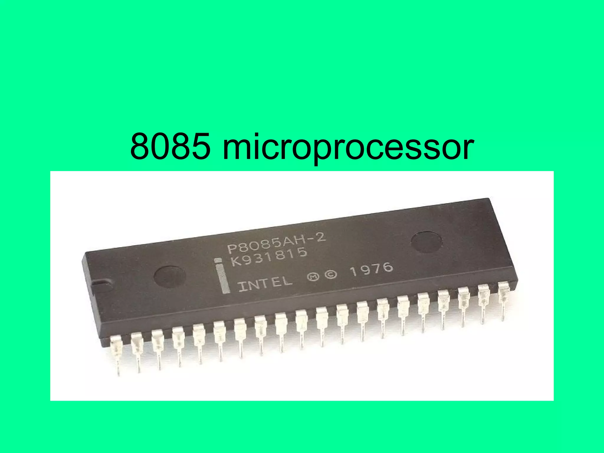
Introduction to 8085 microprocessor, introduced by Intel in 1976, as an update of 8080 with additional pins.
Features include 8-bit structure, 64 kB memory access, 256 I/O ports, and five hardware interrupts.
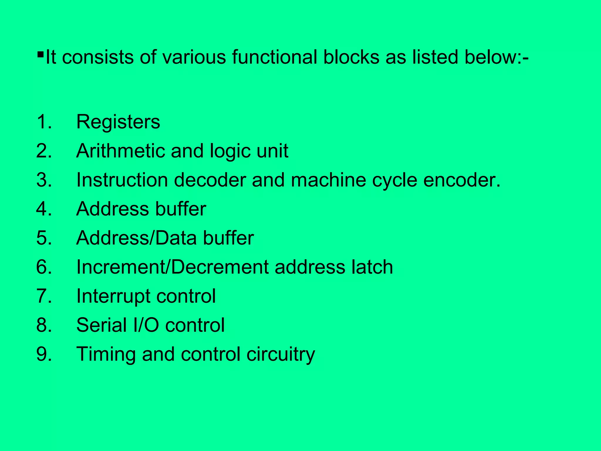
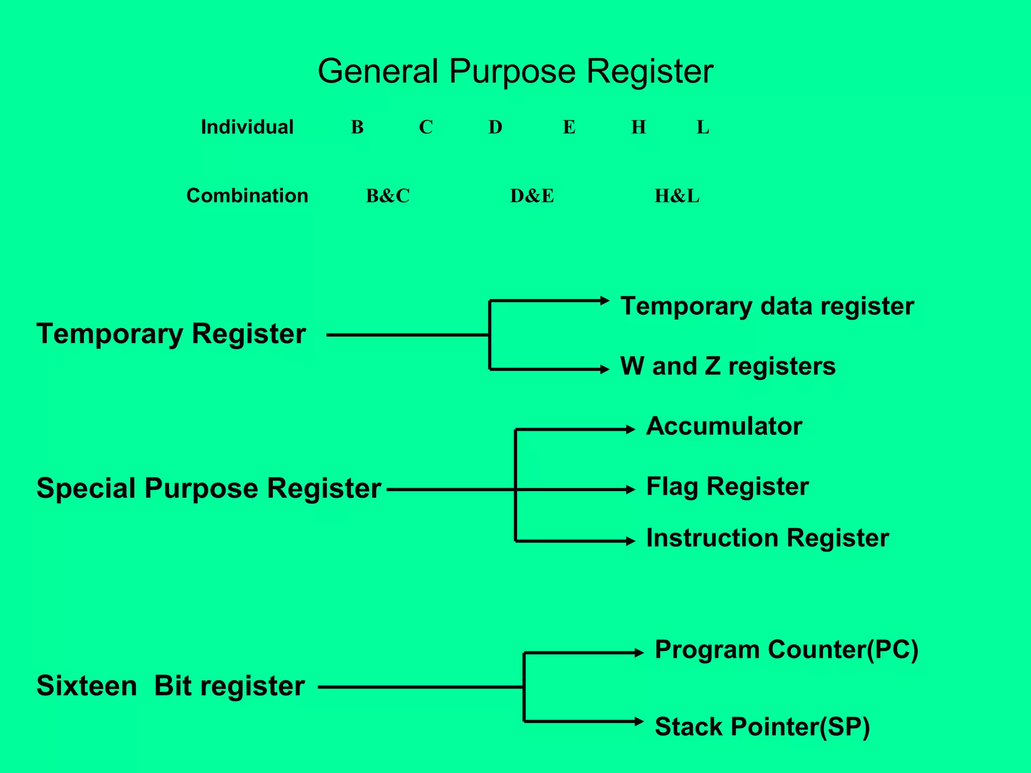
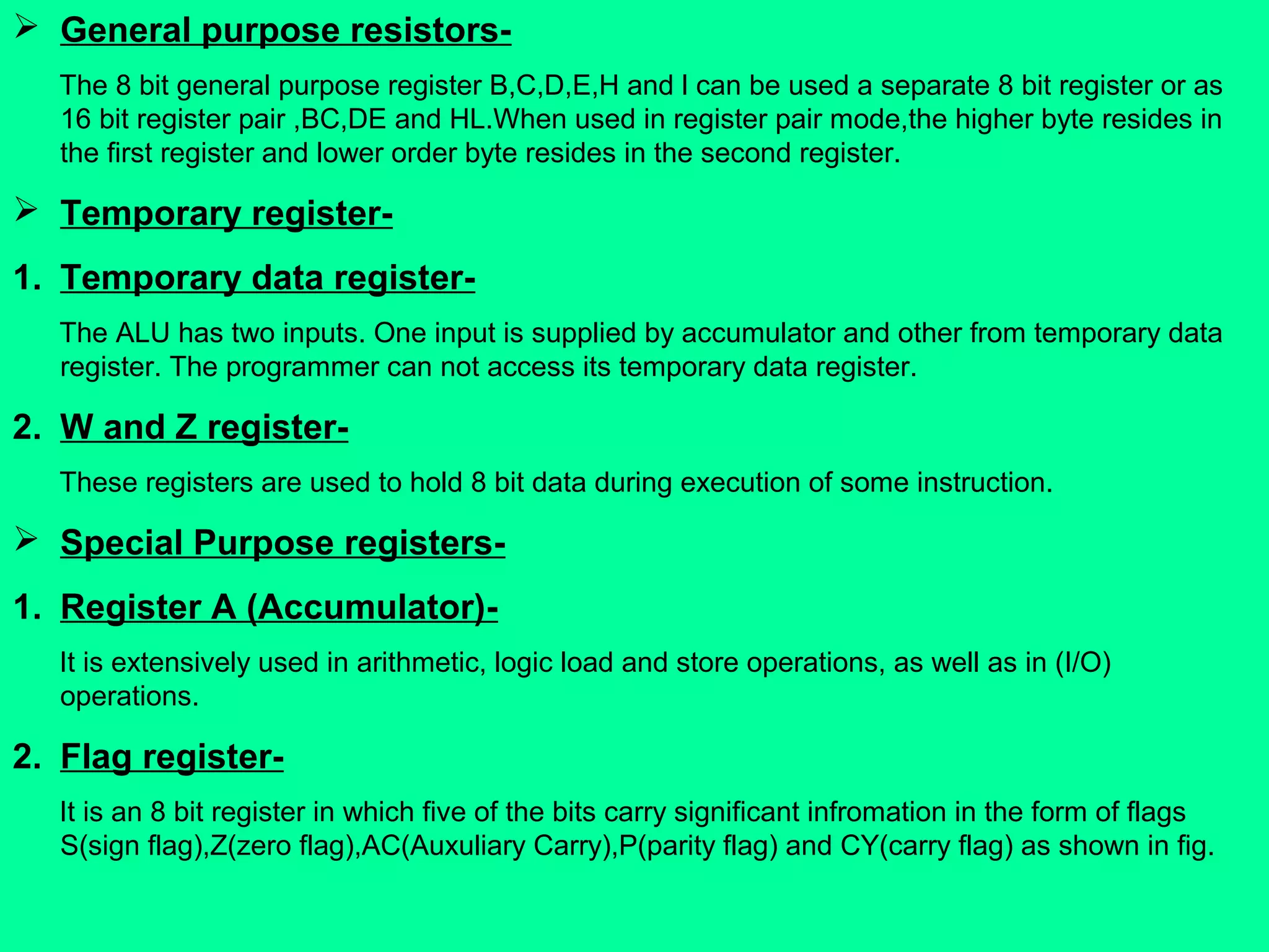
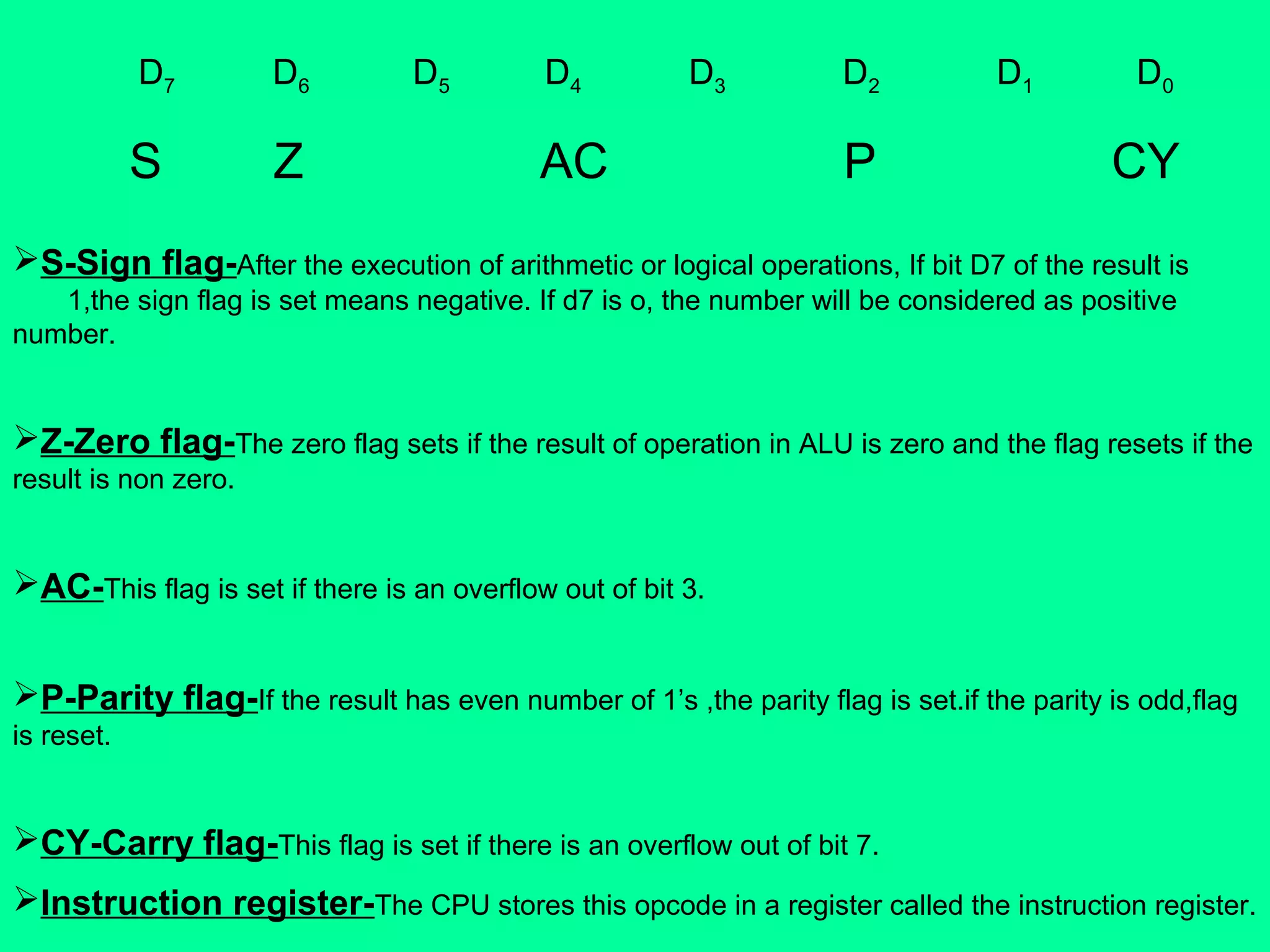
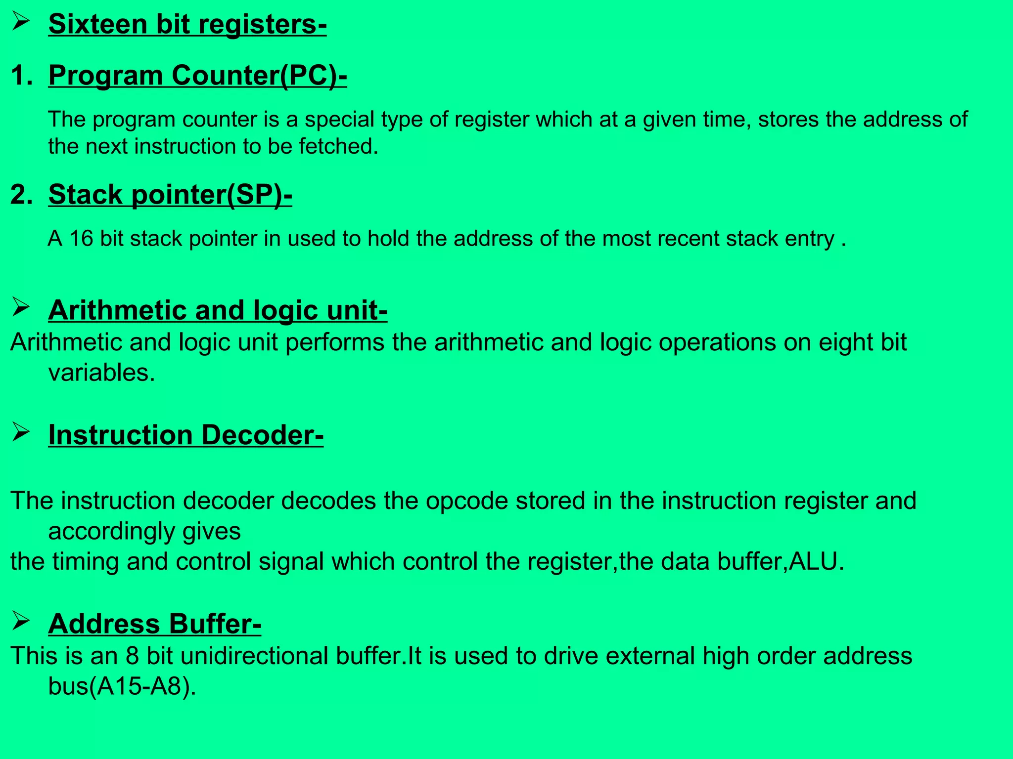
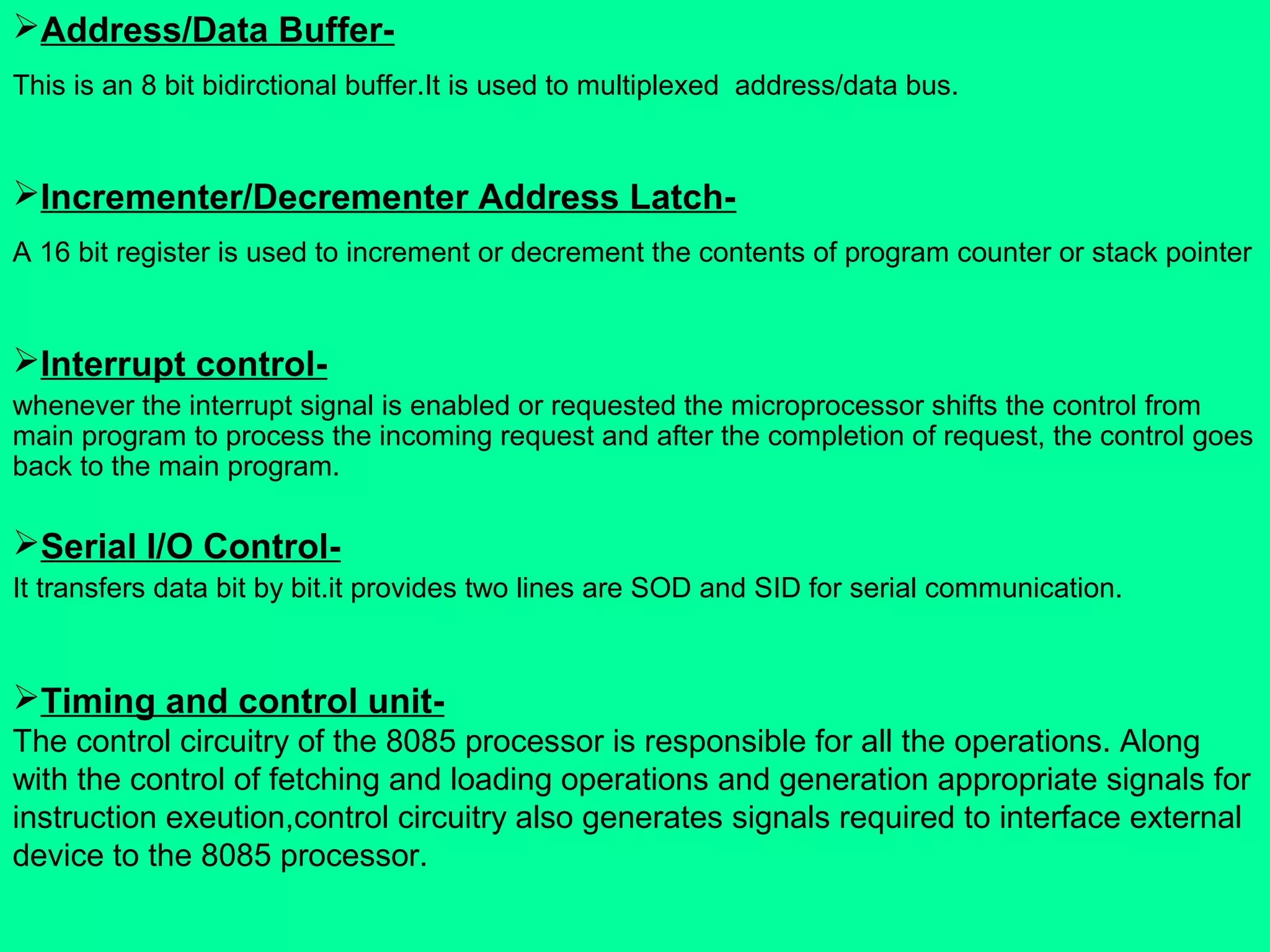
Architecture comprises various functional blocks including ALU, registers, decoders, buffers, and control circuitry.
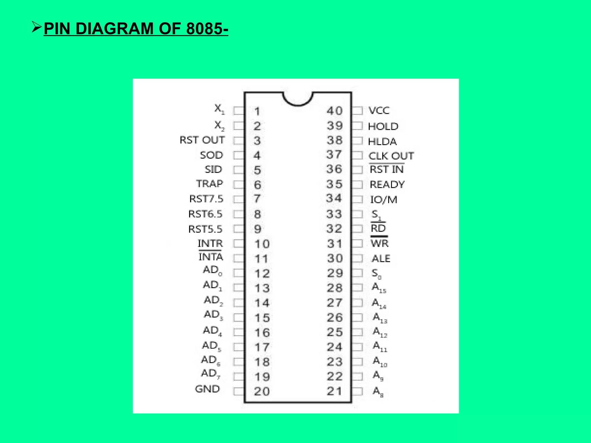
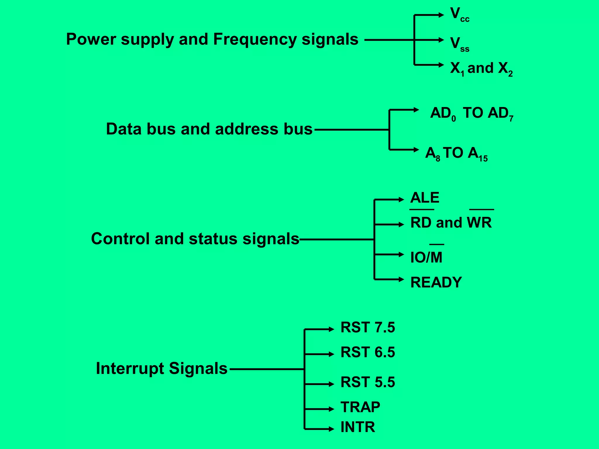
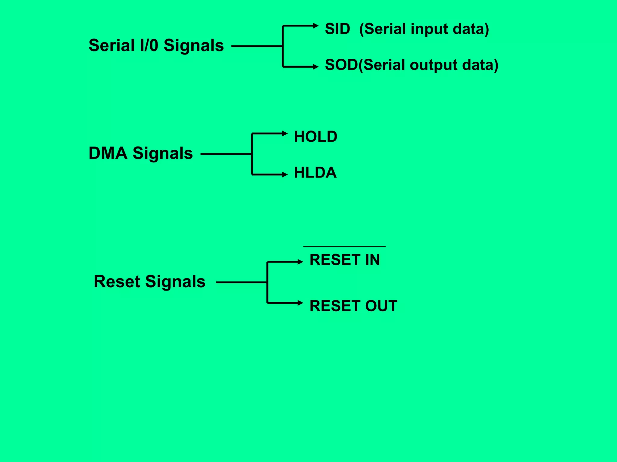
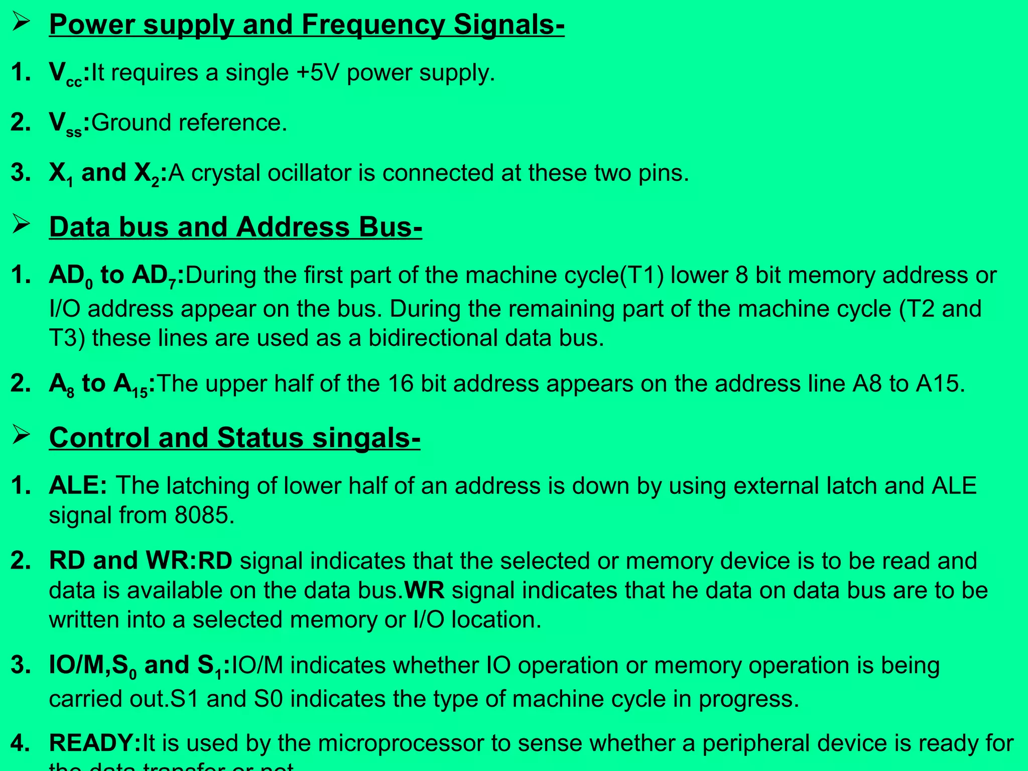
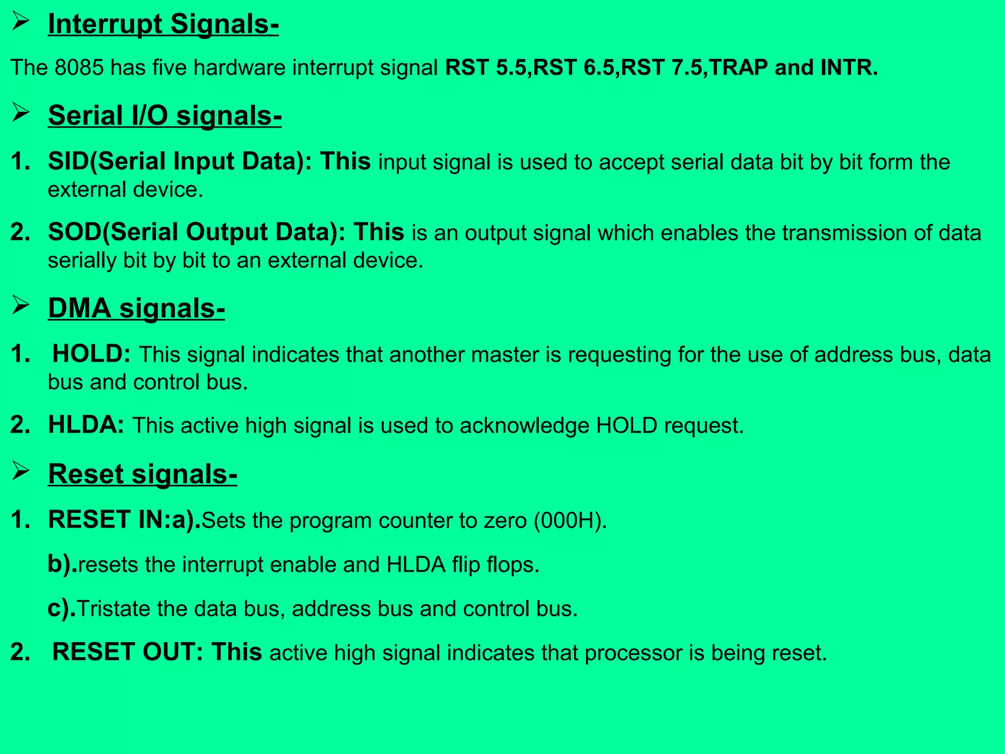
Pin diagram classification into seven groups: power, data/address bus, control, interrupt, serial I/O, DMA, reset signals.
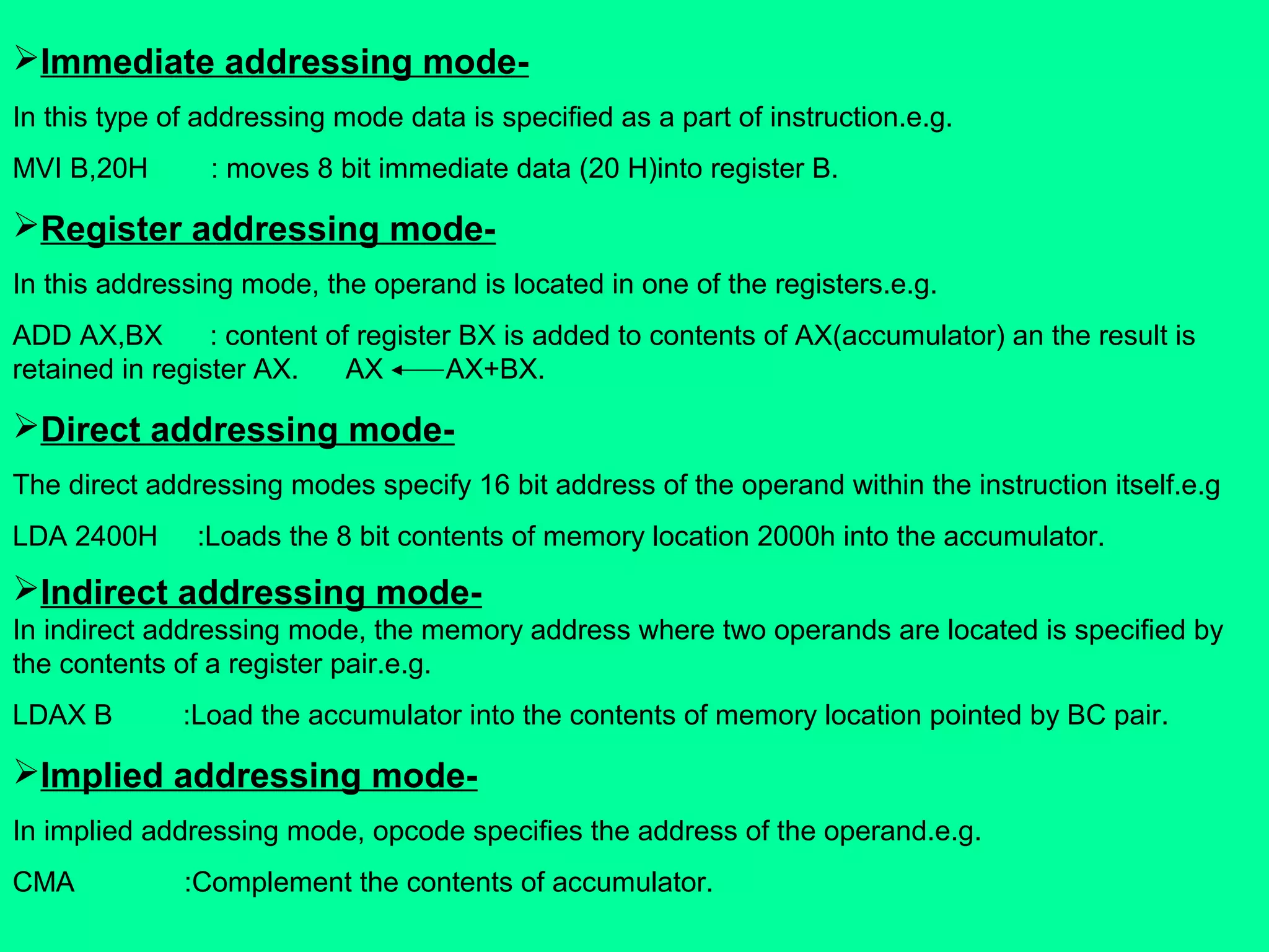
Detailed description of five addressing modes: immediate, register, direct, indirect, and implied addressing for instruction execution.


