Downloaded 186 times
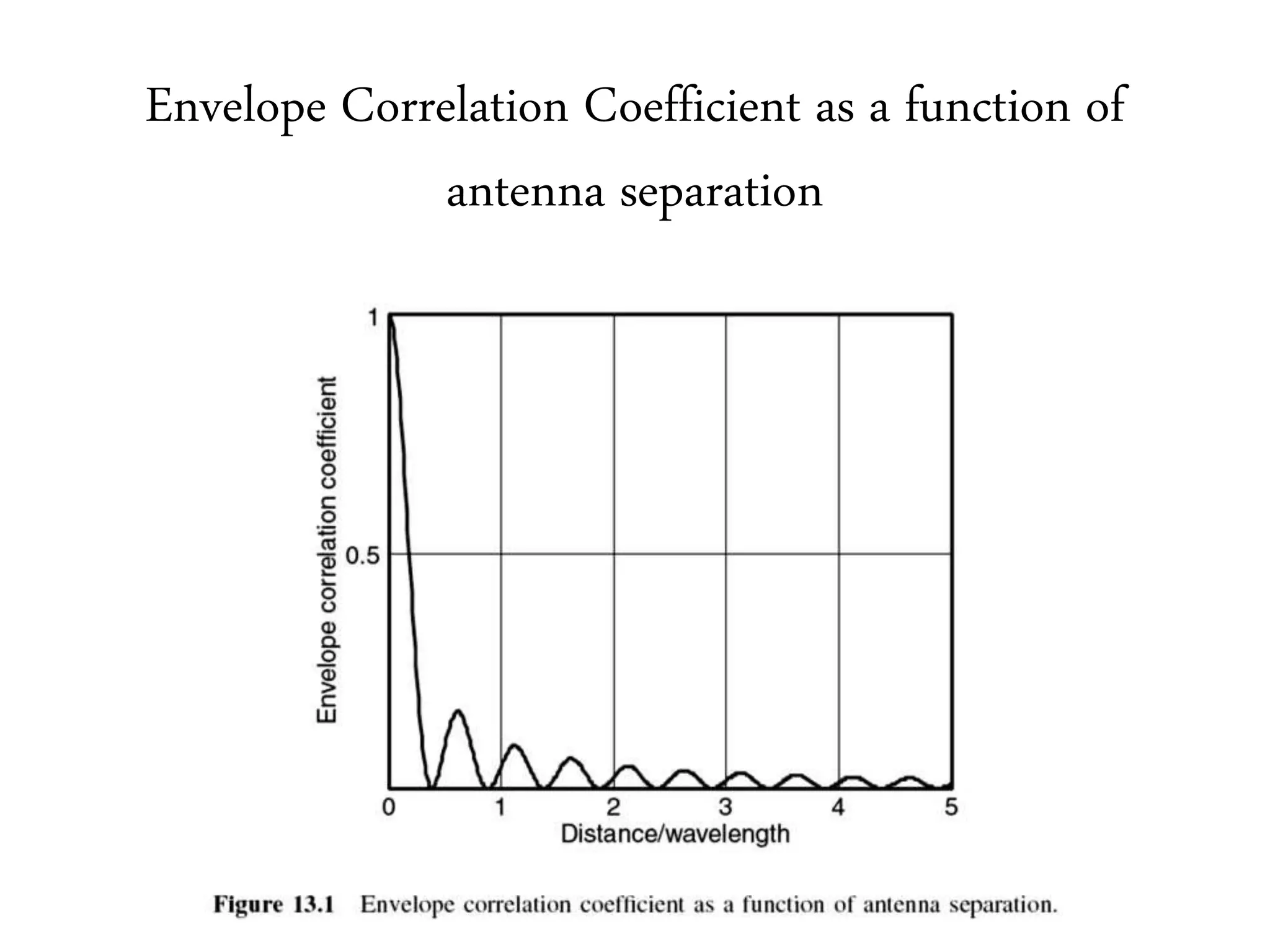
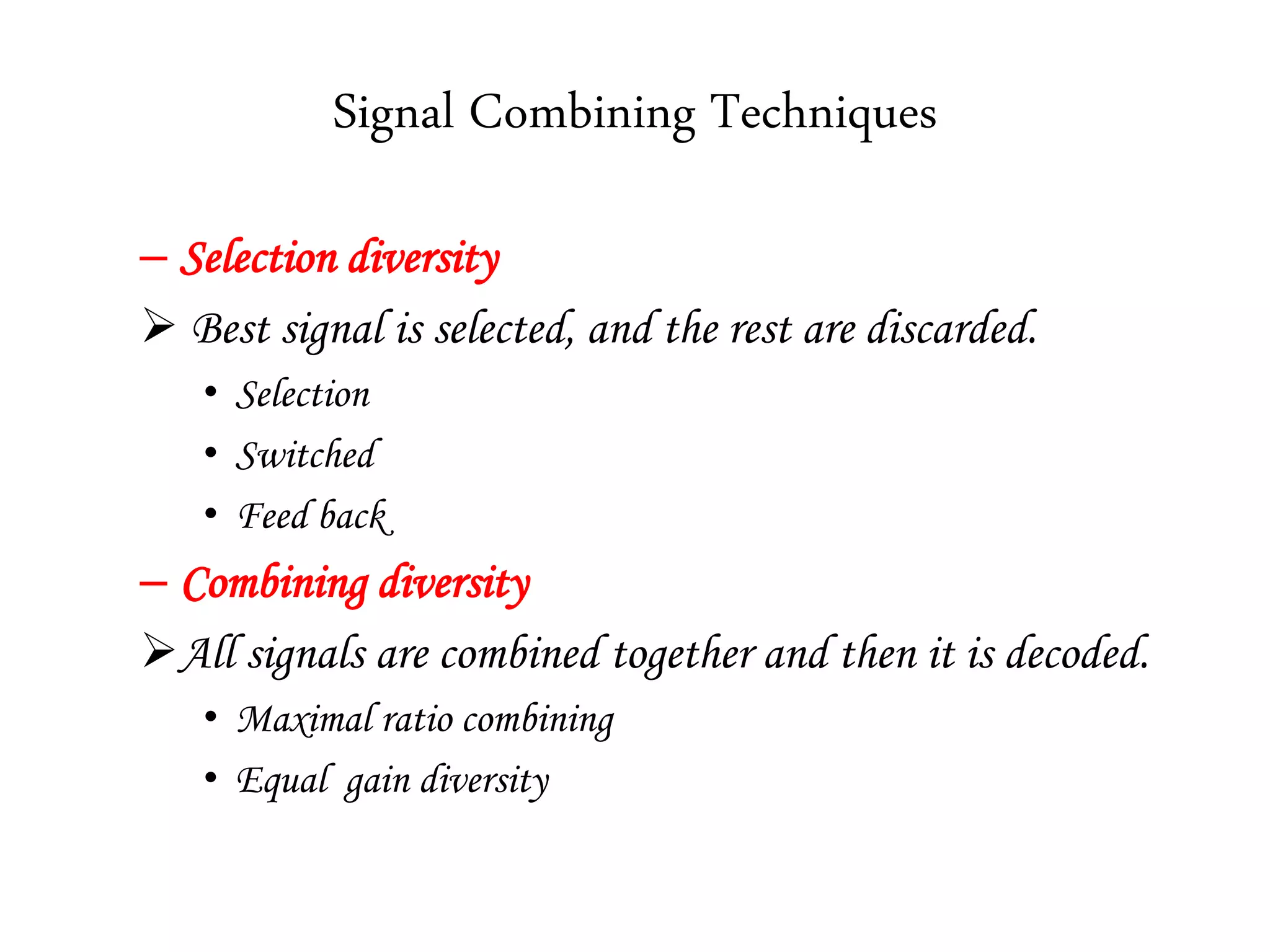
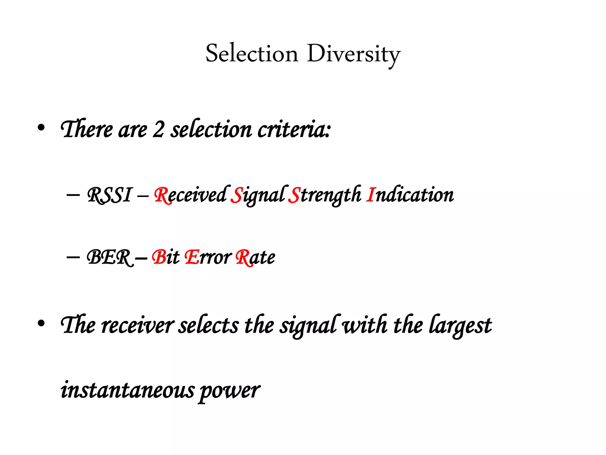
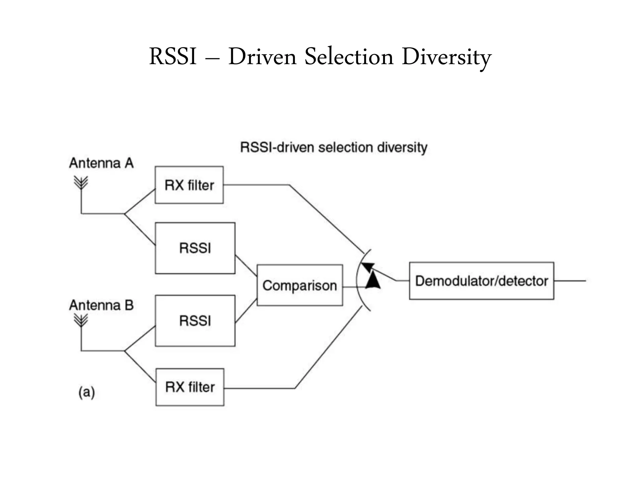
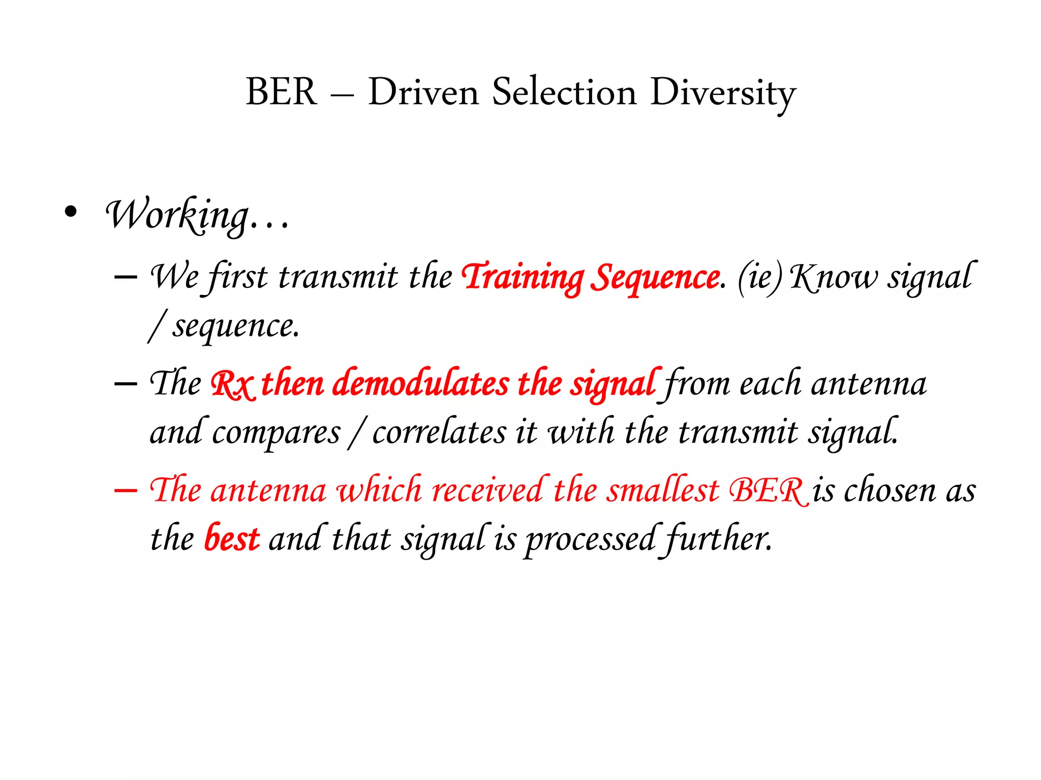
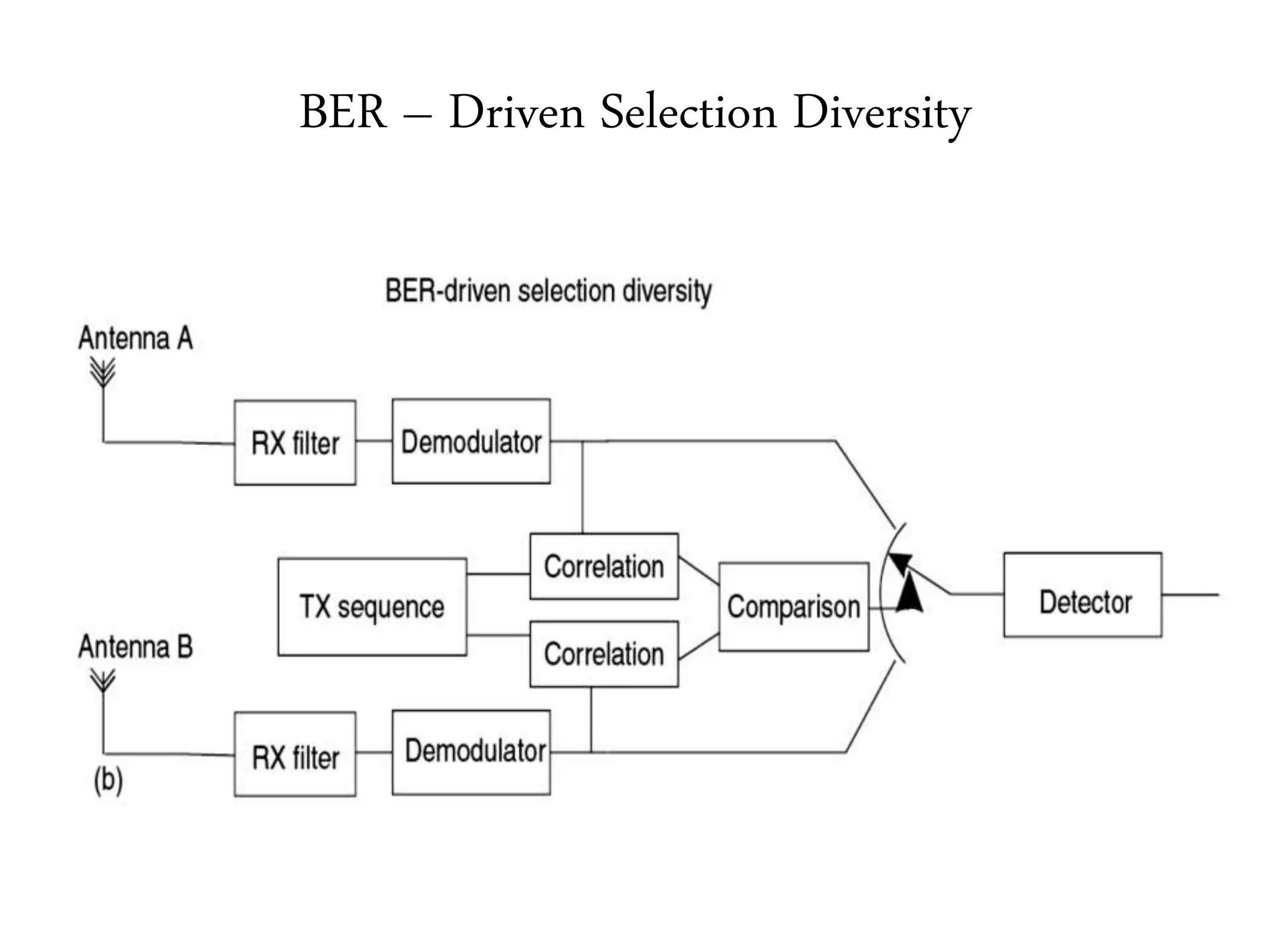
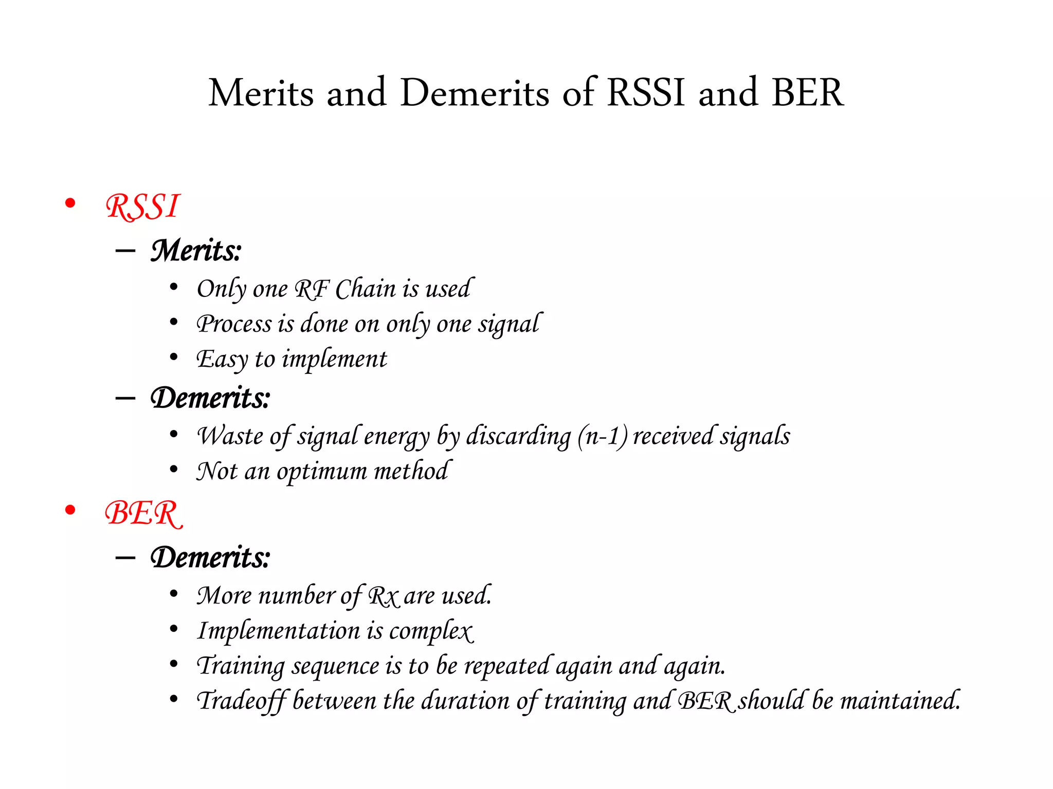
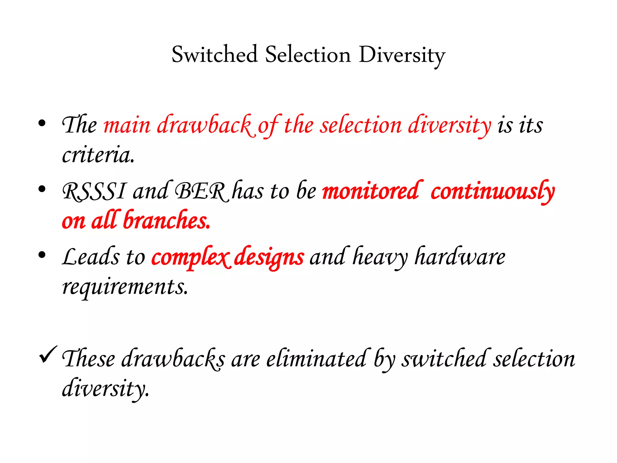
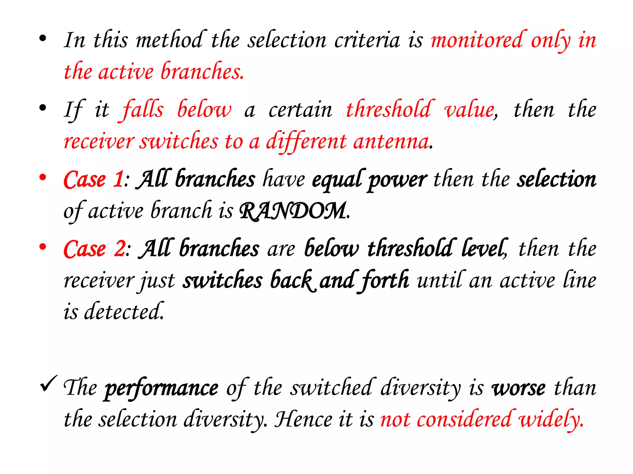
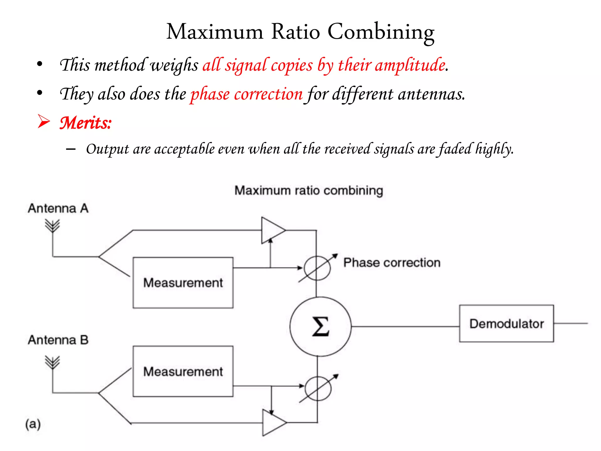
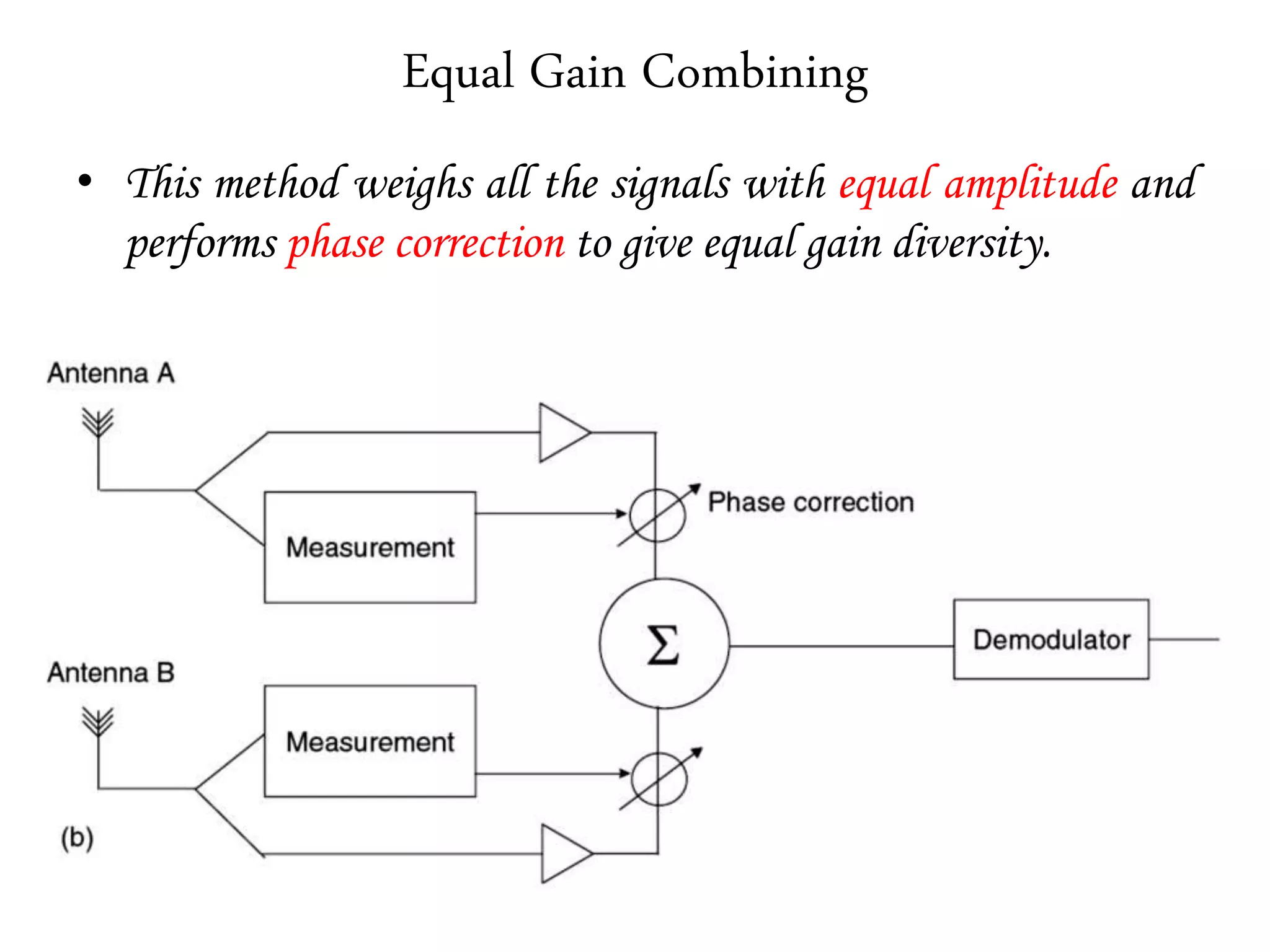

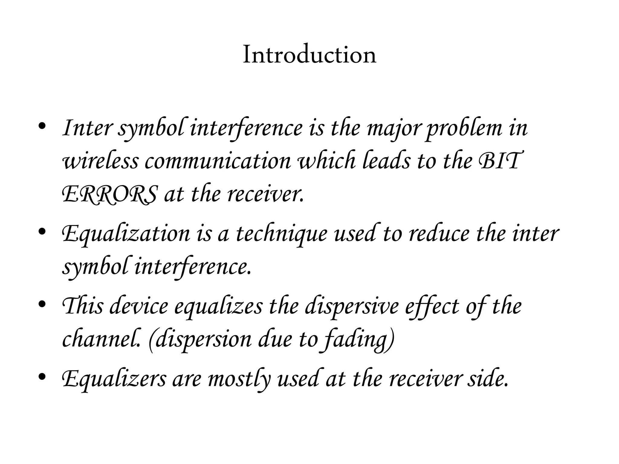
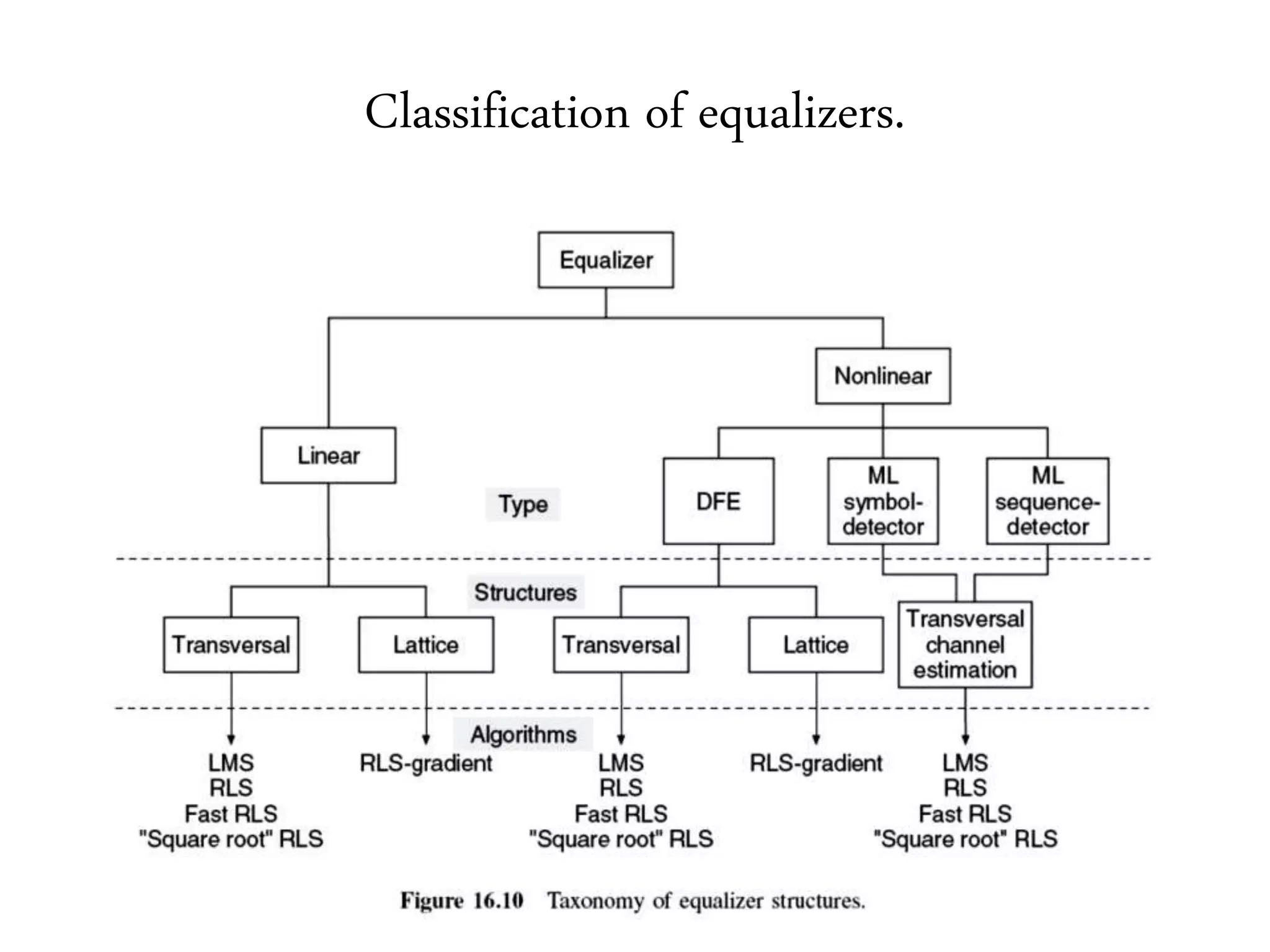
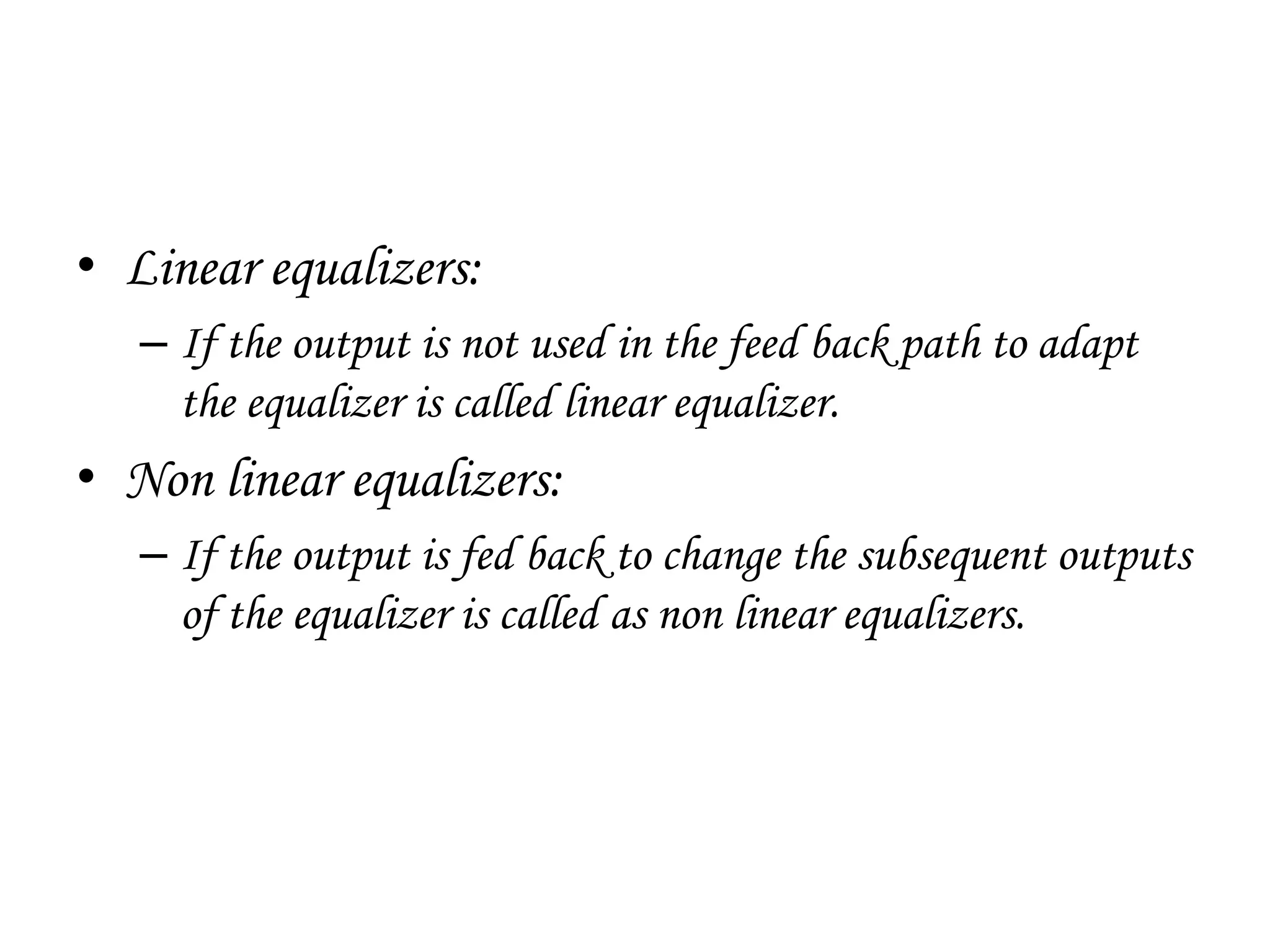
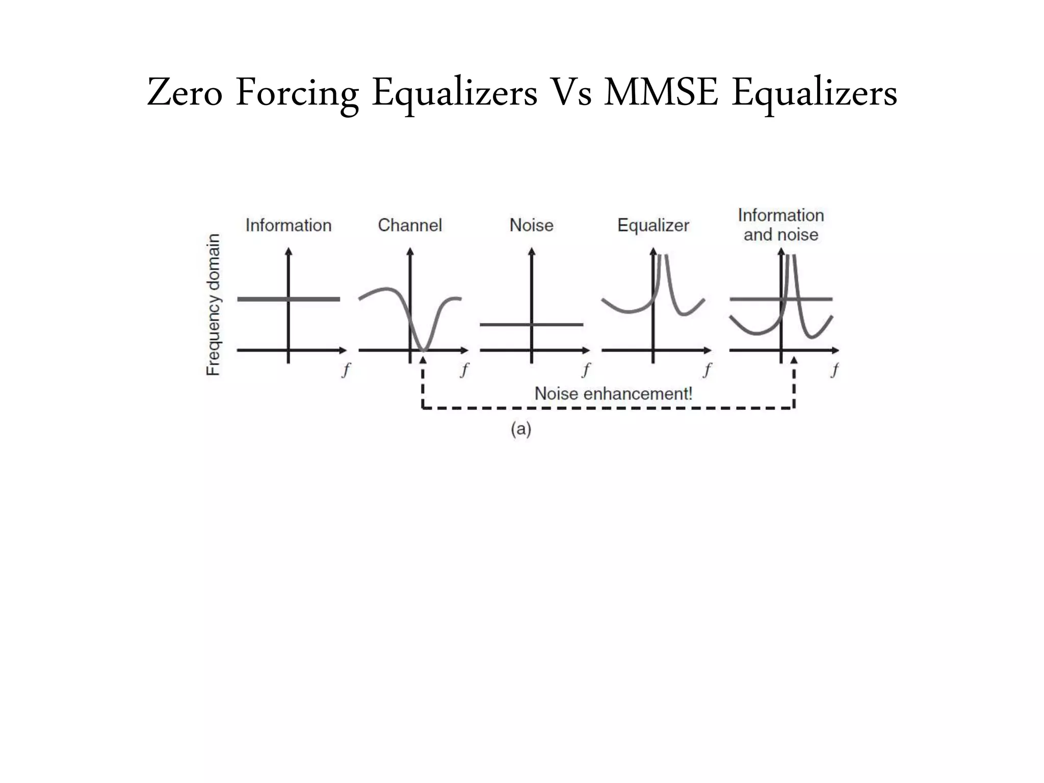
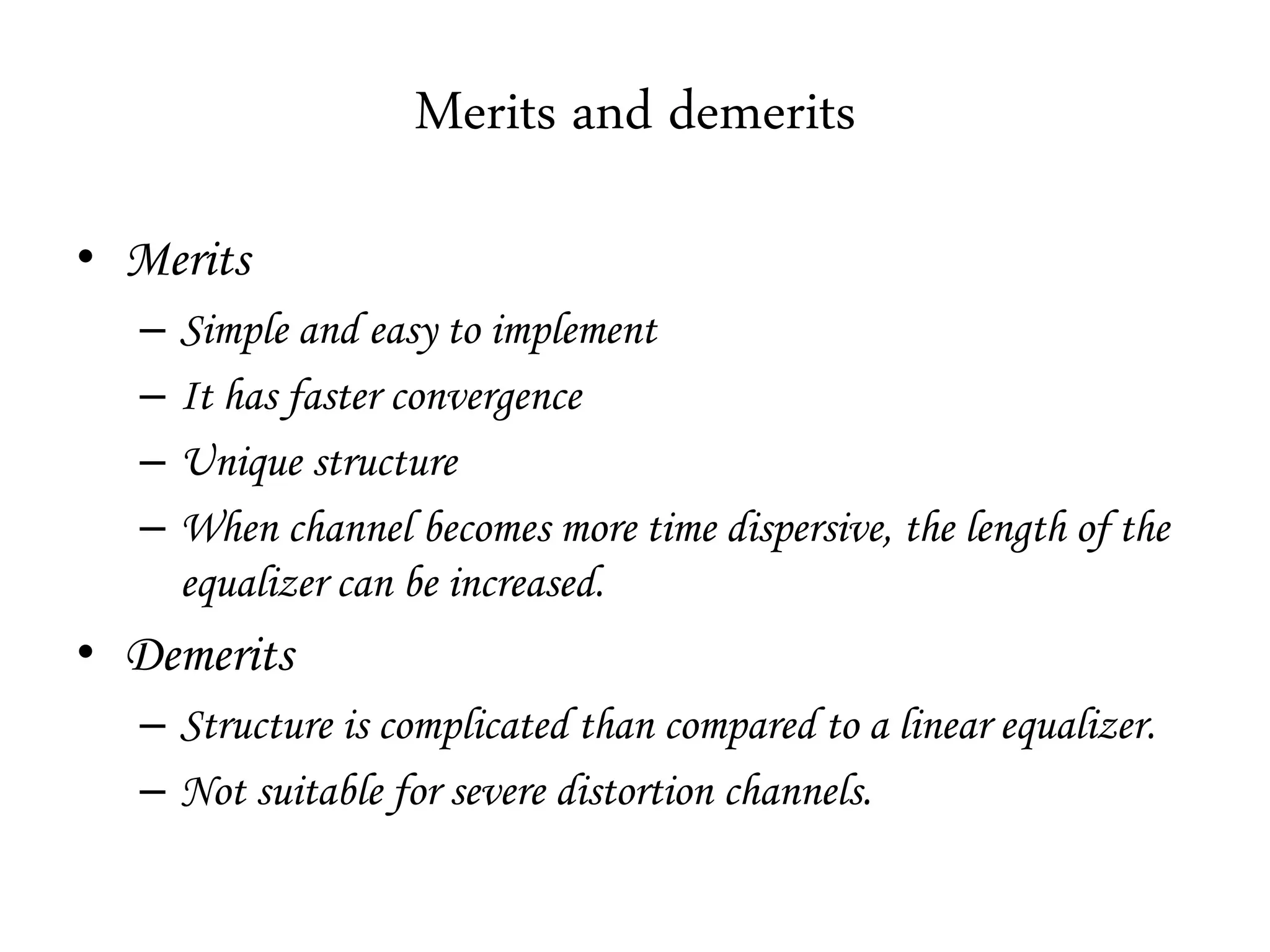
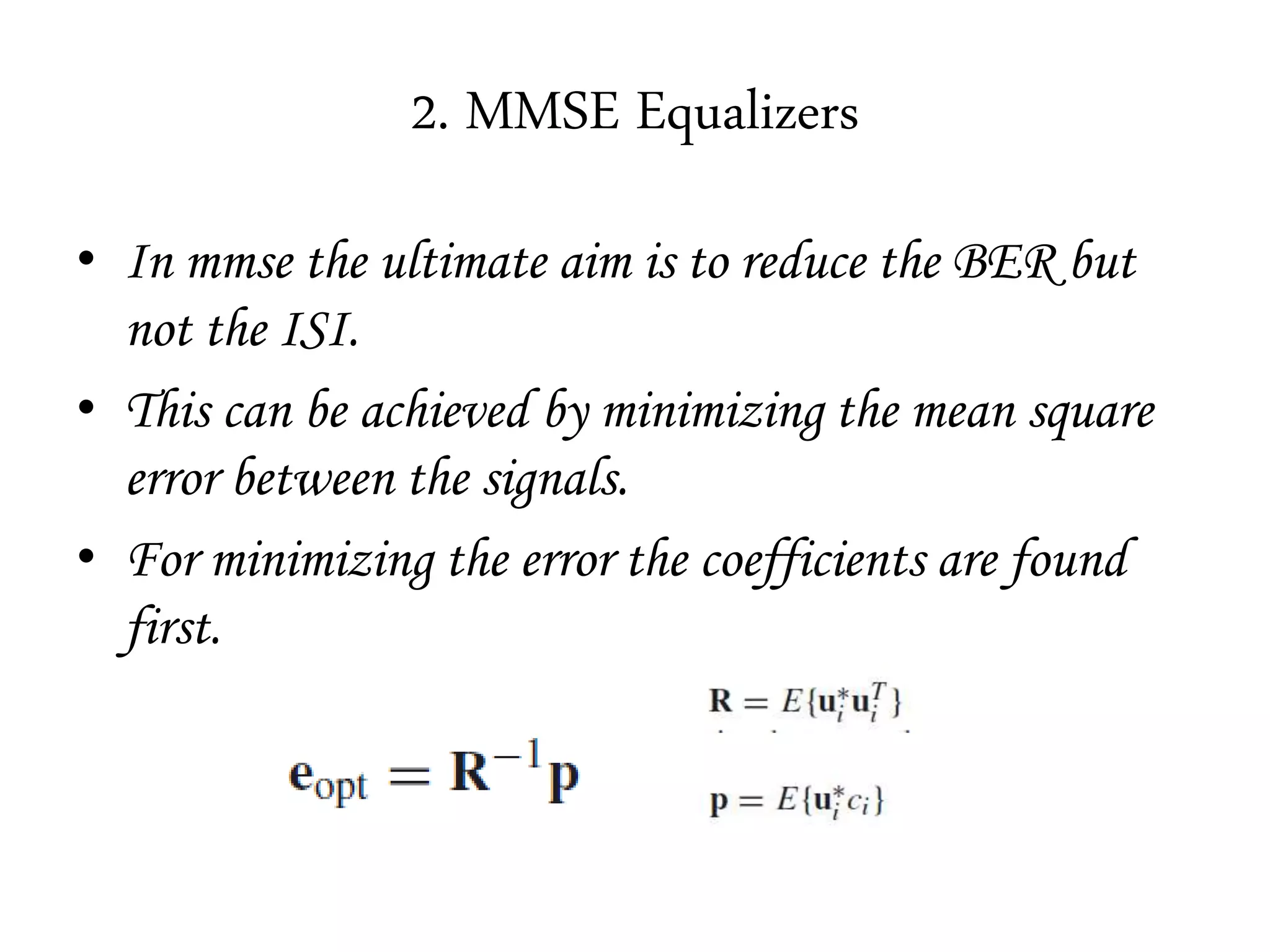
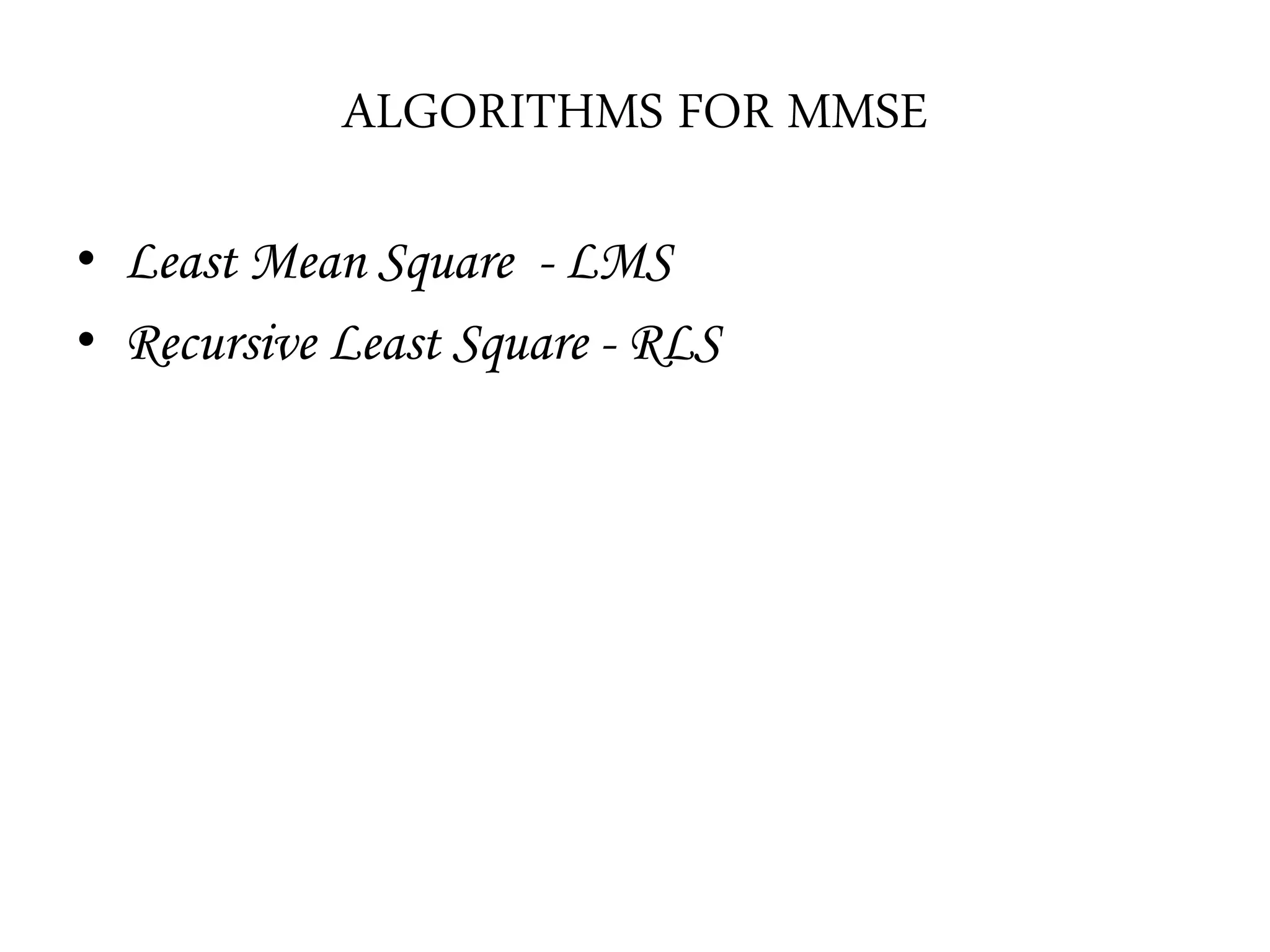

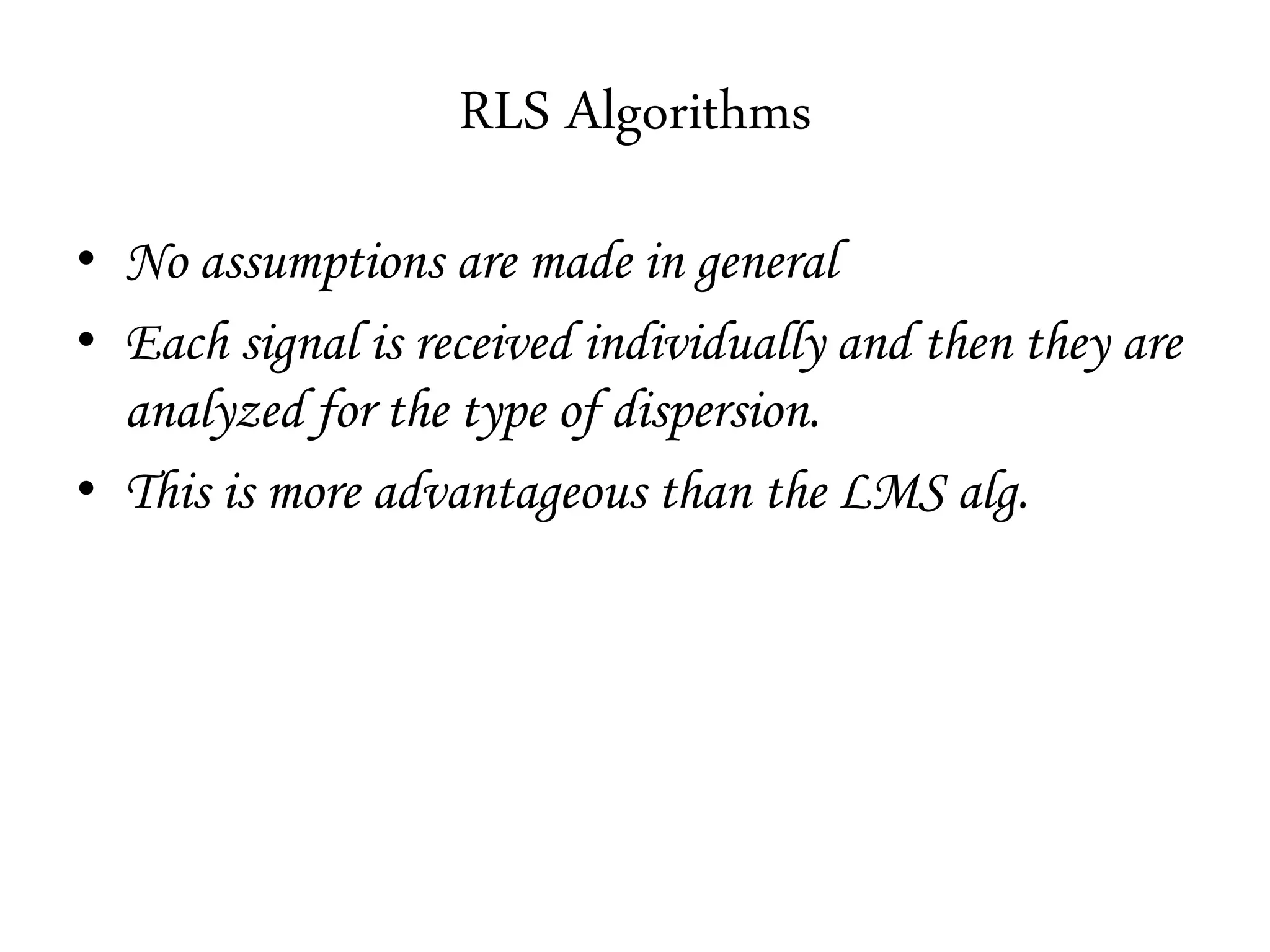

This document provides an overview of signal processing techniques used in wireless systems, including diversity and equalization. It discusses various diversity techniques like spatial, temporal, frequency, angular, and polarization diversity as well as macro and micro diversity. It also explains different types of combining diversity including selection, maximal ratio combining, and equal gain combining. The document concludes with sections on linear equalizers such as zero forcing and MMSE, as well as nonlinear equalizers using algorithms like LMS and RLS.