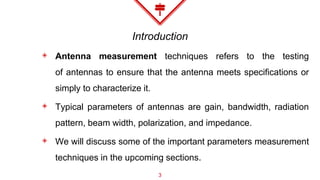
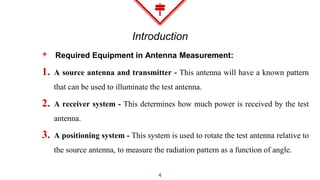
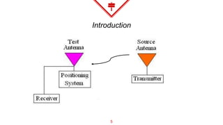
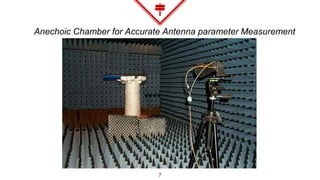
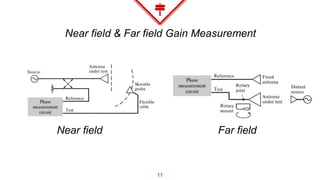
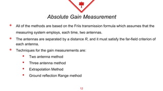
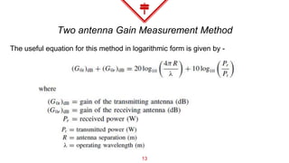
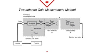
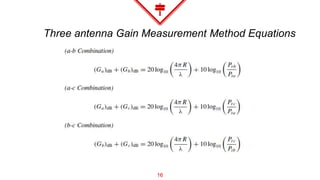
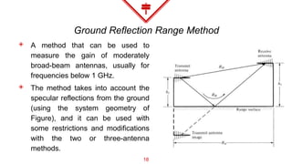
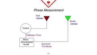
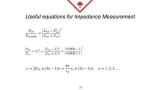
SlideShare a Scribd company logo
Antenna
Measurements
[UNIT – 14 – As per the GTU Syllabus]
Brach: Electronics & Communication Engineering (11)
Semester: B.E (3rd year - 6th Semester)
Subject: Antenna and Wave Propagation (AWP)
GTU Subject Code: 2161003
Prepared By:-
Darshan Bhatt
Assistant Professor, EC Dept.
AIT, Ahmedabad, Gujarat
Content
◈ Introduction
◈ Experimental set ups for measurement of gain
◈ Experimental set ups for measurement of radiation pattern
◈ Experimental set ups for measurement of phase
◈ Experimental set ups for measurement of polarization
◈ Experimental set ups for measurement of terminal
impedance.
2
Introduction
◈ Antenna measurement techniques refers to the testing
of antennas to ensure that the antenna meets specifications or
simply to characterize it.
◈ Typical parameters of antennas are gain, bandwidth, radiation
pattern, beam width, polarization, and impedance.
◈ We will discuss some of the important parameters measurement
techniques in the upcoming sections.
3
Introduction
◈ Required Equipment in Antenna Measurement:
1. A source antenna and transmitter - This antenna will have a known pattern
that can be used to illuminate the test antenna.
2. A receiver system - This determines how much power is received by the test
antenna.
3. A positioning system - This system is used to rotate the test antenna relative to
the source antenna, to measure the radiation pattern as a function of angle.
4
Introduction
5
Introduction
◈ Anechoic Chamber:
◈ Anechoic chambers are indoor antenna ranges.
◈ The walls, ceilings and floor are lined with special electromagnetic wave absorbing material.
◈ Indoor ranges are desirable because the test conditions can be much more tightly controlled
than that of outdoor ranges.
◈ The material is often jagged in shape as well, making these chambers quite interesting to see.
◈ The jagged triangle shapes are designed so that what is reflected from them tends to spread in
random directions, and what is added together from all the random reflections tends to add
incoherently and is thus suppressed further.
6
Anechoic Chamber for Accurate Antenna parameter Measurement
7
Experimental Setup for
Gain Measurement
1
8
Gain Measurement
◈ The most important figure of merit that describes the performance of a radiator is the
gain.
◈ The choice of either depends largely on the frequency of operation.
◈ Antenna gains are not usually measured at frequencies below 1 MHz.
◈ Usually there are two basic methods that can be used to measure the gain of an
electromagnetic radiator
 Absolute-gain
 Gain-transfer or gain-comparison
9
Gain Measurement
◈ The absolute-gain method is used to calibrate antennas that can then be used as
standards for gain measurements, and it requires no a priori knowledge of the gains of
the antennas.
◈ Gain-transfer methods must be used in conjunction with standard gain antennas to
determine the absolute gain of the antenna under test (AUT)
◈ The two antennas that are most widely used and universally accepted as gain standards
are
◈ Resonant λ/2 dipole
◈ Pyramidal horn antenna
10
Near field & Far field Gain Measurement
11
Near field Far field
Absolute Gain Measurement
◈ All of the methods are based on the Friis transmission formula which assumes that the
measuring system employs, each time, two antennas.
◈ The antennas are separated by a distance R, and it must satisfy the far-field criterion of
each antenna.
◈ Techniques for the gain measurements are:
• Two antenna method
• Three antenna method
• Extrapolation Method
• Ground reflection Range method
12
Two antenna Gain Measurement Method
13
The useful equation for this method in logarithmic form is given by -
Two antenna Gain Measurement Method
14
Three antenna Gain Measurement Method
15
• If the two antennas in the measuring system are not identical, three
antennas (a, b, c) must be employed and three measurements must
be made (using all combinations of the three) to determine the gain
of each of the three.
Three antenna Gain Measurement Method Equations
16
Extrapolation Gain Measurement
◈ The extrapolation method is an absolute-gain method, which can be used with the
three-antenna method.
◈ It was developed to rigorously account for possible errors due to proximity,
multipath, and non identical antennas.
◈ If none of the antennas used in the measurements are circularly polarized, the
method yields the gains and polarizations of all three antennas.
◈ If only one antenna is circularly polarized, this method yields only the gain and
polarization of the circularly polarized antenna.
◈ The method fails if two or more antennas are circularly polarized.
17
Ground Reflection Range Method
◈ A method that can be used to
measure the gain of moderately
broad-beam antennas, usually for
frequencies below 1 GHz.
◈ The method takes into account the
specular reflections from the ground
(using the system geometry of
Figure), and it can be used with
some restrictions and modifications
with the two or three-antenna
methods.
18
Ground Reflection Range Method –Useful Equations
19
Experimental Setup for radiation
pattern measurement
2
20
Radiation Pattern Measurement
◈ An example should make the
process reasonably clear. Suppose
the radiation pattern of a microstrip
antenna is to be obtained.
◈ As is usual, let the direction the
patch faces ('normal' to the surface
of the patch) be towards the z-axis.
Suppose the source antenna
illuminates the test antenna from +y-
direction, as shown in Figure.
21
Experimental Setup for Phase
measurement
3
22
Phase Measurement
23
Phase Measurement
◈ The probe antenna should have good polarization purity, so that it can pick
up one component of the received field.
◈ To get the other orthogonal component, it could simply be rotated or another
probe antenna used.
◈ If the test antennas are very far from each other and the reference (source)
waveform can not be fed directly into the phase measurement circuit (this
happens at low frequencies and large outdoor ranges where many
wavelengths becomes a large distance), then a standard antenna with
known phase characteristics is used to transmit a wave, which is used to
compare with the received signal from the test antenna.
24
Experimental Setup for Polarization
measurement
4
25
Polarization Measurement
◈ The far-field polarization of an antenna is usually measured at distances
where the field radiated by the antenna forms, in a small region, a plane
wave that propagates in the outward radial direction.
◈ The general polarization of an antenna is characterized by the axial ratio
(AR), the sense of rotation (CW or CCW, RH or LH), and the tilt angle τ .
◈ The tilt angle is used to identify the spatial orientation of the ellipse, and it is
usually measured clockwise from the reference direction.
26
Polarization Measurement
◈ There are a number of techniques that can be used to measure the
polarization state of a radiator and they can be classified into three main
categories:
1. Those that yield partial polarization information.
2. Those that yield complete polarization in formation but require a
polarization standard for comparison. They are referred to as comparison
methods.
3. Those that yield complete polarization information and require no a priori
polarization knowledge or no polarization standard. They are designated
as absolute methods.
27
Polarization Measurement
◈ To perform the measurements, the
antenna under test can be used
either in the transmitting or in the
receiving mode.
◈ Usually the transmitting mode is
adopted. The method requires that a
linearly polarized antenna, usually a
dipole, be used to probe the
polarization in the plane that
contains the direction of the desired
polarization. The arrangement is
shown in Figure.
28
Experimental set ups for
measurement of terminal impedance
5
29
Impedance Measurement
◈ Associated with an antenna, there are two types of impedances: a self and a
mutual impedance.
◈ When the antenna is radiating into an unbounded medium and there is no
coupling between it and other antennas or surrounding obstacles, the self-
impedance is also the driving-point impedance of the antenna.
◈ If there is coupling between the antenna under test and other sources or
obstacles, the driving-point impedance is a function of its self-impedance and
the mutual impedances between it and the other sources or obstacles. In
practice, the driving-point impedance is usually referred to as the input
impedance.
30
Useful equations for Impedance Measurement
31
References
◈ “Antenna theory – Analysis and Design”, 3rd edition by
Constantine A. Balanis, John Wiley and Sons publications
◈ www.antennatheory.com
32
Thank You

More Related Content

What's hot

Travelling Wave Tube
Travelling Wave TubeTravelling Wave Tube
Travelling Wave Tube
Binita Khua
 
3_Antenna Array [Modlue 4] (1).pdf
3_Antenna Array [Modlue 4] (1).pdf3_Antenna Array [Modlue 4] (1).pdf
3_Antenna Array [Modlue 4] (1).pdf
sumanthsai22
 
Aperture antennas
Aperture antennasAperture antennas
Aperture antennas
GopinathD17
 
Antenna PARAMETERS
Antenna PARAMETERSAntenna PARAMETERS
Antenna PARAMETERS
AJAL A J
 
Beam forming- New Technology
Beam forming- New TechnologyBeam forming- New Technology
Beam forming- New Technology
PARNIKA GUPTA
 
MicroStrip Antenna
MicroStrip AntennaMicroStrip Antenna
MicroStrip Antenna
Tarek Nader
 
Mobile Radio Propagations
Mobile Radio PropagationsMobile Radio Propagations
Mobile Radio Propagations
METHODIST COLLEGE OF ENGG & TECH
 
ANTENNA AND ITS TYPES
ANTENNA  AND ITS TYPESANTENNA  AND ITS TYPES
ANTENNA AND ITS TYPES
Surbhi Sharma
 
EC6602-Antenna fundamentals new
EC6602-Antenna fundamentals new EC6602-Antenna fundamentals new
EC6602-Antenna fundamentals new
krishnamrm
 
Broadside array vs end fire array
Broadside array vs end fire arrayBroadside array vs end fire array
Broadside array vs end fire array
AJAL A J
 
Antenna measurements
Antenna measurementsAntenna measurements
Antenna measurements
Imran Rafiq
 
Channel assignment strategies
Channel assignment strategiesChannel assignment strategies
Channel assignment strategies
AJAL A J
 
Pulse shaping
Pulse shapingPulse shaping
Pulse shaping
Ramraj Choudhary
 
Satellite link design
Satellite link designSatellite link design
Satellite link design
RAVIKIRAN ANANDE
 
Horn antenna
Horn antennaHorn antenna
Horn antenna
Alankrit Mishra
 
Antennas and their types
Antennas and their typesAntennas and their types
Antennas and their types
venati munishareddy
 
Chap 5 (small scale fading)
Chap 5 (small scale fading)Chap 5 (small scale fading)
Chap 5 (small scale fading)asadkhan1327
 
Antennas and Wave Propagation
Antennas and Wave PropagationAntennas and Wave Propagation
Antennas and Wave Propagation
VenkataRatnam14
 
Antenna Parameters Part 2
Antenna Parameters Part 2Antenna Parameters Part 2
Antenna Parameters Part 2
Roma Rico Flores
 

What's hot (20)

Travelling Wave Tube
Travelling Wave TubeTravelling Wave Tube
Travelling Wave Tube
 
3_Antenna Array [Modlue 4] (1).pdf
3_Antenna Array [Modlue 4] (1).pdf3_Antenna Array [Modlue 4] (1).pdf
3_Antenna Array [Modlue 4] (1).pdf
 
Aperture antennas
Aperture antennasAperture antennas
Aperture antennas
 
Antenna PARAMETERS
Antenna PARAMETERSAntenna PARAMETERS
Antenna PARAMETERS
 
Beam forming- New Technology
Beam forming- New TechnologyBeam forming- New Technology
Beam forming- New Technology
 
MicroStrip Antenna
MicroStrip AntennaMicroStrip Antenna
MicroStrip Antenna
 
Mobile Radio Propagations
Mobile Radio PropagationsMobile Radio Propagations
Mobile Radio Propagations
 
Antenna system
Antenna systemAntenna system
Antenna system
 
ANTENNA AND ITS TYPES
ANTENNA  AND ITS TYPESANTENNA  AND ITS TYPES
ANTENNA AND ITS TYPES
 
EC6602-Antenna fundamentals new
EC6602-Antenna fundamentals new EC6602-Antenna fundamentals new
EC6602-Antenna fundamentals new
 
Broadside array vs end fire array
Broadside array vs end fire arrayBroadside array vs end fire array
Broadside array vs end fire array
 
Antenna measurements
Antenna measurementsAntenna measurements
Antenna measurements
 
Channel assignment strategies
Channel assignment strategiesChannel assignment strategies
Channel assignment strategies
 
Pulse shaping
Pulse shapingPulse shaping
Pulse shaping
 
Satellite link design
Satellite link designSatellite link design
Satellite link design
 
Horn antenna
Horn antennaHorn antenna
Horn antenna
 
Antennas and their types
Antennas and their typesAntennas and their types
Antennas and their types
 
Chap 5 (small scale fading)
Chap 5 (small scale fading)Chap 5 (small scale fading)
Chap 5 (small scale fading)
 
Antennas and Wave Propagation
Antennas and Wave PropagationAntennas and Wave Propagation
Antennas and Wave Propagation
 
Antenna Parameters Part 2
Antenna Parameters Part 2Antenna Parameters Part 2
Antenna Parameters Part 2
 

Similar to Antenna Measurements

Book 3: “Antennae Techniques”
Book 3: “Antennae Techniques”Book 3: “Antennae Techniques”
Book 3: “Antennae Techniques”
Timour Chaikhraziev
 
What is the radiation pattern?
What is the radiation pattern?What is the radiation pattern?
What is the radiation pattern?
Antenna Manufacturer Coco
 
Long distance wireless link
Long distance wireless linkLong distance wireless link
Long distance wireless linkMario B.
 
Antenna Array Tutorial for dummies making of.pdf
Antenna Array Tutorial for dummies making of.pdfAntenna Array Tutorial for dummies making of.pdf
Antenna Array Tutorial for dummies making of.pdf
bborgilius
 
Antenna Measurements PowerPoint presentation
Antenna Measurements PowerPoint presentationAntenna Measurements PowerPoint presentation
Antenna Measurements PowerPoint presentation
shivanimali9096
 
antenna book.pdf
antenna book.pdfantenna book.pdf
antenna book.pdf
SandeepSran4
 
Antenna lecture course CHapter 2_(2)[1].pdf
Antenna lecture course  CHapter 2_(2)[1].pdfAntenna lecture course  CHapter 2_(2)[1].pdf
Antenna lecture course CHapter 2_(2)[1].pdf
AbrahamGadissa
 
Antenna arrays
Antenna arraysAntenna arrays
Antenna arrays
AJAL A J
 
Monitoring Open Pit
Monitoring Open PitMonitoring Open Pit
Monitoring Open Pit
JOSE ESPEJO VASQUEZ
 
4 test methods for 5 g base station antenna ota - C&T RF Antennas Inc
4 test methods for 5 g base station antenna ota  - C&T RF Antennas Inc4 test methods for 5 g base station antenna ota  - C&T RF Antennas Inc
4 test methods for 5 g base station antenna ota - C&T RF Antennas Inc
Antenna Manufacturer Coco
 
Reflector Antennas Design and mathematical expression_1.pptx
Reflector Antennas Design and mathematical expression_1.pptxReflector Antennas Design and mathematical expression_1.pptx
Reflector Antennas Design and mathematical expression_1.pptx
jaychoudhary37
 
Travelling Wave, Broadband Antennas, Frequency-independent Antennas
Travelling Wave, Broadband Antennas,  Frequency-independent AntennasTravelling Wave, Broadband Antennas,  Frequency-independent Antennas
Travelling Wave, Broadband Antennas, Frequency-independent Antennas
Roma Rico Flores
 
EC6602 - AWP UNI-4
EC6602 - AWP UNI-4EC6602 - AWP UNI-4
EC6602 - AWP UNI-4
krishnamrm
 
TOTAL STATION: THEORY, USES AND APPLICATIONS.
TOTAL STATION: THEORY, USES AND APPLICATIONS. TOTAL STATION: THEORY, USES AND APPLICATIONS.
TOTAL STATION: THEORY, USES AND APPLICATIONS.
Ahmed Nassar
 
RADIOMETER AND BASICS OF SATELLITE COMMUNICATION SYSTEMS
RADIOMETER AND BASICS OF SATELLITE COMMUNICATION SYSTEMSRADIOMETER AND BASICS OF SATELLITE COMMUNICATION SYSTEMS
RADIOMETER AND BASICS OF SATELLITE COMMUNICATION SYSTEMS
ShivangiSingh241
 

Similar to Antenna Measurements (20)

TRS
TRSTRS
TRS
 
Kailash 2
Kailash 2Kailash 2
Kailash 2
 
Freznal zone
Freznal zoneFreznal zone
Freznal zone
 
Book 3: “Antennae Techniques”
Book 3: “Antennae Techniques”Book 3: “Antennae Techniques”
Book 3: “Antennae Techniques”
 
What is the radiation pattern?
What is the radiation pattern?What is the radiation pattern?
What is the radiation pattern?
 
Long distance wireless link
Long distance wireless linkLong distance wireless link
Long distance wireless link
 
Antenna Array Tutorial for dummies making of.pdf
Antenna Array Tutorial for dummies making of.pdfAntenna Array Tutorial for dummies making of.pdf
Antenna Array Tutorial for dummies making of.pdf
 
Antenna Measurements PowerPoint presentation
Antenna Measurements PowerPoint presentationAntenna Measurements PowerPoint presentation
Antenna Measurements PowerPoint presentation
 
8 slides
8 slides8 slides
8 slides
 
antenna book.pdf
antenna book.pdfantenna book.pdf
antenna book.pdf
 
Antenna lecture course CHapter 2_(2)[1].pdf
Antenna lecture course  CHapter 2_(2)[1].pdfAntenna lecture course  CHapter 2_(2)[1].pdf
Antenna lecture course CHapter 2_(2)[1].pdf
 
Antenna arrays
Antenna arraysAntenna arrays
Antenna arrays
 
Monitoring Open Pit
Monitoring Open PitMonitoring Open Pit
Monitoring Open Pit
 
4 test methods for 5 g base station antenna ota - C&T RF Antennas Inc
4 test methods for 5 g base station antenna ota  - C&T RF Antennas Inc4 test methods for 5 g base station antenna ota  - C&T RF Antennas Inc
4 test methods for 5 g base station antenna ota - C&T RF Antennas Inc
 
Reflector Antennas Design and mathematical expression_1.pptx
Reflector Antennas Design and mathematical expression_1.pptxReflector Antennas Design and mathematical expression_1.pptx
Reflector Antennas Design and mathematical expression_1.pptx
 
Travelling Wave, Broadband Antennas, Frequency-independent Antennas
Travelling Wave, Broadband Antennas,  Frequency-independent AntennasTravelling Wave, Broadband Antennas,  Frequency-independent Antennas
Travelling Wave, Broadband Antennas, Frequency-independent Antennas
 
EC6602 - AWP UNI-4
EC6602 - AWP UNI-4EC6602 - AWP UNI-4
EC6602 - AWP UNI-4
 
TOTAL STATION: THEORY, USES AND APPLICATIONS.
TOTAL STATION: THEORY, USES AND APPLICATIONS. TOTAL STATION: THEORY, USES AND APPLICATIONS.
TOTAL STATION: THEORY, USES AND APPLICATIONS.
 
Satellite antennas
Satellite antennasSatellite antennas
Satellite antennas
 
RADIOMETER AND BASICS OF SATELLITE COMMUNICATION SYSTEMS
RADIOMETER AND BASICS OF SATELLITE COMMUNICATION SYSTEMSRADIOMETER AND BASICS OF SATELLITE COMMUNICATION SYSTEMS
RADIOMETER AND BASICS OF SATELLITE COMMUNICATION SYSTEMS
 

More from Darshan Bhatt

Unit 1-PN junction Diode.pptx
Unit 1-PN junction Diode.pptxUnit 1-PN junction Diode.pptx
Unit 1-PN junction Diode.pptx
Darshan Bhatt
 
Z Transform
Z TransformZ Transform
Z Transform
Darshan Bhatt
 
Overview of an OSI reference Model
Overview of an OSI reference ModelOverview of an OSI reference Model
Overview of an OSI reference Model
Darshan Bhatt
 
Basics of microstrip slot line
Basics of microstrip slot lineBasics of microstrip slot line
Basics of microstrip slot line
Darshan Bhatt
 
POP3 Proxy platform for e-mail filtering
POP3 Proxy platform for e-mail filteringPOP3 Proxy platform for e-mail filtering
POP3 Proxy platform for e-mail filtering
Darshan Bhatt
 
Transformation of Random variables & noise concepts
Transformation of Random variables & noise concepts Transformation of Random variables & noise concepts
Transformation of Random variables & noise concepts
Darshan Bhatt
 
GRAMSAT - For rural development & tele-education
GRAMSAT - For rural development & tele-educationGRAMSAT - For rural development & tele-education
GRAMSAT - For rural development & tele-education
Darshan Bhatt
 
Side Lobe Level (SLL) Reduction Methods in Antenna
Side Lobe Level (SLL) Reduction Methods in AntennaSide Lobe Level (SLL) Reduction Methods in Antenna
Side Lobe Level (SLL) Reduction Methods in Antenna
Darshan Bhatt
 
Research skills
Research skillsResearch skills
Research skills
Darshan Bhatt
 
Prediction methods of Rayleigh scattering losses
Prediction methods of Rayleigh scattering lossesPrediction methods of Rayleigh scattering losses
Prediction methods of Rayleigh scattering losses
Darshan Bhatt
 
Applications of Information Theory
Applications of Information TheoryApplications of Information Theory
Applications of Information Theory
Darshan Bhatt
 
Concept of Flip OFDM and its applications
Concept of Flip OFDM and its applicationsConcept of Flip OFDM and its applications
Concept of Flip OFDM and its applications
Darshan Bhatt
 
SALMAN KHAN - The Contributor personality
SALMAN KHAN -  The Contributor personality SALMAN KHAN -  The Contributor personality
SALMAN KHAN - The Contributor personality Darshan Bhatt
 

More from Darshan Bhatt (14)

Unit 1-PN junction Diode.pptx
Unit 1-PN junction Diode.pptxUnit 1-PN junction Diode.pptx
Unit 1-PN junction Diode.pptx
 
Z Transform
Z TransformZ Transform
Z Transform
 
Overview of an OSI reference Model
Overview of an OSI reference ModelOverview of an OSI reference Model
Overview of an OSI reference Model
 
Basics of microstrip slot line
Basics of microstrip slot lineBasics of microstrip slot line
Basics of microstrip slot line
 
POP3 Proxy platform for e-mail filtering
POP3 Proxy platform for e-mail filteringPOP3 Proxy platform for e-mail filtering
POP3 Proxy platform for e-mail filtering
 
Transformation of Random variables & noise concepts
Transformation of Random variables & noise concepts Transformation of Random variables & noise concepts
Transformation of Random variables & noise concepts
 
GRAMSAT - For rural development & tele-education
GRAMSAT - For rural development & tele-educationGRAMSAT - For rural development & tele-education
GRAMSAT - For rural development & tele-education
 
Side Lobe Level (SLL) Reduction Methods in Antenna
Side Lobe Level (SLL) Reduction Methods in AntennaSide Lobe Level (SLL) Reduction Methods in Antenna
Side Lobe Level (SLL) Reduction Methods in Antenna
 
Research skills
Research skillsResearch skills
Research skills
 
Prediction methods of Rayleigh scattering losses
Prediction methods of Rayleigh scattering lossesPrediction methods of Rayleigh scattering losses
Prediction methods of Rayleigh scattering losses
 
Applications of Information Theory
Applications of Information TheoryApplications of Information Theory
Applications of Information Theory
 
Concept of Flip OFDM and its applications
Concept of Flip OFDM and its applicationsConcept of Flip OFDM and its applications
Concept of Flip OFDM and its applications
 
MY CPD PRESENTATION
MY CPD PRESENTATIONMY CPD PRESENTATION
MY CPD PRESENTATION
 
SALMAN KHAN - The Contributor personality
SALMAN KHAN -  The Contributor personality SALMAN KHAN -  The Contributor personality
SALMAN KHAN - The Contributor personality
 

Recently uploaded

ML for identifying fraud using open blockchain data.pptx
ML for identifying fraud using open blockchain data.pptxML for identifying fraud using open blockchain data.pptx
ML for identifying fraud using open blockchain data.pptx
Vijay Dialani, PhD
 
Hierarchical Digital Twin of a Naval Power System
Hierarchical Digital Twin of a Naval Power SystemHierarchical Digital Twin of a Naval Power System
Hierarchical Digital Twin of a Naval Power System
Kerry Sado
 
Standard Reomte Control Interface - Neometrix
Standard Reomte Control Interface - NeometrixStandard Reomte Control Interface - Neometrix
Standard Reomte Control Interface - Neometrix
Neometrix_Engineering_Pvt_Ltd
 
road safety engineering r s e unit 3.pdf
road safety engineering  r s e unit 3.pdfroad safety engineering  r s e unit 3.pdf
road safety engineering r s e unit 3.pdf
VENKATESHvenky89705
 
Governing Equations for Fundamental Aerodynamics_Anderson2010.pdf
Governing Equations for Fundamental Aerodynamics_Anderson2010.pdfGoverning Equations for Fundamental Aerodynamics_Anderson2010.pdf
Governing Equations for Fundamental Aerodynamics_Anderson2010.pdf
WENKENLI1
 
J.Yang, ICLR 2024, MLILAB, KAIST AI.pdf
J.Yang,  ICLR 2024, MLILAB, KAIST AI.pdfJ.Yang,  ICLR 2024, MLILAB, KAIST AI.pdf
J.Yang, ICLR 2024, MLILAB, KAIST AI.pdf
MLILAB
 
Design and Analysis of Algorithms-DP,Backtracking,Graphs,B&B
Design and Analysis of Algorithms-DP,Backtracking,Graphs,B&BDesign and Analysis of Algorithms-DP,Backtracking,Graphs,B&B
Design and Analysis of Algorithms-DP,Backtracking,Graphs,B&B
Sreedhar Chowdam
 
Industrial Training at Shahjalal Fertilizer Company Limited (SFCL)
Industrial Training at Shahjalal Fertilizer Company Limited (SFCL)Industrial Training at Shahjalal Fertilizer Company Limited (SFCL)
Industrial Training at Shahjalal Fertilizer Company Limited (SFCL)
MdTanvirMahtab2
 
Student information management system project report ii.pdf
Student information management system project report ii.pdfStudent information management system project report ii.pdf
Student information management system project report ii.pdf
Kamal Acharya
 
space technology lecture notes on satellite
space technology lecture notes on satellitespace technology lecture notes on satellite
space technology lecture notes on satellite
ongomchris
 
NO1 Uk best vashikaran specialist in delhi vashikaran baba near me online vas...
NO1 Uk best vashikaran specialist in delhi vashikaran baba near me online vas...NO1 Uk best vashikaran specialist in delhi vashikaran baba near me online vas...
NO1 Uk best vashikaran specialist in delhi vashikaran baba near me online vas...
Amil Baba Dawood bangali
 
Top 10 Oil and Gas Projects in Saudi Arabia 2024.pdf
Top 10 Oil and Gas Projects in Saudi Arabia 2024.pdfTop 10 Oil and Gas Projects in Saudi Arabia 2024.pdf
Top 10 Oil and Gas Projects in Saudi Arabia 2024.pdf
Teleport Manpower Consultant
 
Final project report on grocery store management system..pdf
Final project report on grocery store management system..pdfFinal project report on grocery store management system..pdf
Final project report on grocery store management system..pdf
Kamal Acharya
 
HYDROPOWER - Hydroelectric power generation
HYDROPOWER - Hydroelectric power generationHYDROPOWER - Hydroelectric power generation
HYDROPOWER - Hydroelectric power generation
Robbie Edward Sayers
 
Immunizing Image Classifiers Against Localized Adversary Attacks
Immunizing Image Classifiers Against Localized Adversary AttacksImmunizing Image Classifiers Against Localized Adversary Attacks
Immunizing Image Classifiers Against Localized Adversary Attacks
gerogepatton
 
The role of big data in decision making.
The role of big data in decision making.The role of big data in decision making.
The role of big data in decision making.
ankuprajapati0525
 
WATER CRISIS and its solutions-pptx 1234
WATER CRISIS and its solutions-pptx 1234WATER CRISIS and its solutions-pptx 1234
WATER CRISIS and its solutions-pptx 1234
AafreenAbuthahir2
 
一比一原版(IIT毕业证)伊利诺伊理工大学毕业证成绩单专业办理
一比一原版(IIT毕业证)伊利诺伊理工大学毕业证成绩单专业办理一比一原版(IIT毕业证)伊利诺伊理工大学毕业证成绩单专业办理
一比一原版(IIT毕业证)伊利诺伊理工大学毕业证成绩单专业办理
zwunae
 
Sachpazis:Terzaghi Bearing Capacity Estimation in simple terms with Calculati...
Sachpazis:Terzaghi Bearing Capacity Estimation in simple terms with Calculati...Sachpazis:Terzaghi Bearing Capacity Estimation in simple terms with Calculati...
Sachpazis:Terzaghi Bearing Capacity Estimation in simple terms with Calculati...
Dr.Costas Sachpazis
 
DESIGN A COTTON SEED SEPARATION MACHINE.docx
DESIGN A COTTON SEED SEPARATION MACHINE.docxDESIGN A COTTON SEED SEPARATION MACHINE.docx
DESIGN A COTTON SEED SEPARATION MACHINE.docx
FluxPrime1
 

Recently uploaded (20)

ML for identifying fraud using open blockchain data.pptx
ML for identifying fraud using open blockchain data.pptxML for identifying fraud using open blockchain data.pptx
ML for identifying fraud using open blockchain data.pptx
 
Hierarchical Digital Twin of a Naval Power System
Hierarchical Digital Twin of a Naval Power SystemHierarchical Digital Twin of a Naval Power System
Hierarchical Digital Twin of a Naval Power System
 
Standard Reomte Control Interface - Neometrix
Standard Reomte Control Interface - NeometrixStandard Reomte Control Interface - Neometrix
Standard Reomte Control Interface - Neometrix
 
road safety engineering r s e unit 3.pdf
road safety engineering  r s e unit 3.pdfroad safety engineering  r s e unit 3.pdf
road safety engineering r s e unit 3.pdf
 
Governing Equations for Fundamental Aerodynamics_Anderson2010.pdf
Governing Equations for Fundamental Aerodynamics_Anderson2010.pdfGoverning Equations for Fundamental Aerodynamics_Anderson2010.pdf
Governing Equations for Fundamental Aerodynamics_Anderson2010.pdf
 
J.Yang, ICLR 2024, MLILAB, KAIST AI.pdf
J.Yang,  ICLR 2024, MLILAB, KAIST AI.pdfJ.Yang,  ICLR 2024, MLILAB, KAIST AI.pdf
J.Yang, ICLR 2024, MLILAB, KAIST AI.pdf
 
Design and Analysis of Algorithms-DP,Backtracking,Graphs,B&B
Design and Analysis of Algorithms-DP,Backtracking,Graphs,B&BDesign and Analysis of Algorithms-DP,Backtracking,Graphs,B&B
Design and Analysis of Algorithms-DP,Backtracking,Graphs,B&B
 
Industrial Training at Shahjalal Fertilizer Company Limited (SFCL)
Industrial Training at Shahjalal Fertilizer Company Limited (SFCL)Industrial Training at Shahjalal Fertilizer Company Limited (SFCL)
Industrial Training at Shahjalal Fertilizer Company Limited (SFCL)
 
Student information management system project report ii.pdf
Student information management system project report ii.pdfStudent information management system project report ii.pdf
Student information management system project report ii.pdf
 
space technology lecture notes on satellite
space technology lecture notes on satellitespace technology lecture notes on satellite
space technology lecture notes on satellite
 
NO1 Uk best vashikaran specialist in delhi vashikaran baba near me online vas...
NO1 Uk best vashikaran specialist in delhi vashikaran baba near me online vas...NO1 Uk best vashikaran specialist in delhi vashikaran baba near me online vas...
NO1 Uk best vashikaran specialist in delhi vashikaran baba near me online vas...
 
Top 10 Oil and Gas Projects in Saudi Arabia 2024.pdf
Top 10 Oil and Gas Projects in Saudi Arabia 2024.pdfTop 10 Oil and Gas Projects in Saudi Arabia 2024.pdf
Top 10 Oil and Gas Projects in Saudi Arabia 2024.pdf
 
Final project report on grocery store management system..pdf
Final project report on grocery store management system..pdfFinal project report on grocery store management system..pdf
Final project report on grocery store management system..pdf
 
HYDROPOWER - Hydroelectric power generation
HYDROPOWER - Hydroelectric power generationHYDROPOWER - Hydroelectric power generation
HYDROPOWER - Hydroelectric power generation
 
Immunizing Image Classifiers Against Localized Adversary Attacks
Immunizing Image Classifiers Against Localized Adversary AttacksImmunizing Image Classifiers Against Localized Adversary Attacks
Immunizing Image Classifiers Against Localized Adversary Attacks
 
The role of big data in decision making.
The role of big data in decision making.The role of big data in decision making.
The role of big data in decision making.
 
WATER CRISIS and its solutions-pptx 1234
WATER CRISIS and its solutions-pptx 1234WATER CRISIS and its solutions-pptx 1234
WATER CRISIS and its solutions-pptx 1234
 
一比一原版(IIT毕业证)伊利诺伊理工大学毕业证成绩单专业办理
一比一原版(IIT毕业证)伊利诺伊理工大学毕业证成绩单专业办理一比一原版(IIT毕业证)伊利诺伊理工大学毕业证成绩单专业办理
一比一原版(IIT毕业证)伊利诺伊理工大学毕业证成绩单专业办理
 
Sachpazis:Terzaghi Bearing Capacity Estimation in simple terms with Calculati...
Sachpazis:Terzaghi Bearing Capacity Estimation in simple terms with Calculati...Sachpazis:Terzaghi Bearing Capacity Estimation in simple terms with Calculati...
Sachpazis:Terzaghi Bearing Capacity Estimation in simple terms with Calculati...
 
DESIGN A COTTON SEED SEPARATION MACHINE.docx
DESIGN A COTTON SEED SEPARATION MACHINE.docxDESIGN A COTTON SEED SEPARATION MACHINE.docx
DESIGN A COTTON SEED SEPARATION MACHINE.docx
 

Antenna Measurements

  • 1. Antenna Measurements [UNIT – 14 – As per the GTU Syllabus] Brach: Electronics & Communication Engineering (11) Semester: B.E (3rd year - 6th Semester) Subject: Antenna and Wave Propagation (AWP) GTU Subject Code: 2161003 Prepared By:- Darshan Bhatt Assistant Professor, EC Dept. AIT, Ahmedabad, Gujarat
  • 2. Content ◈ Introduction ◈ Experimental set ups for measurement of gain ◈ Experimental set ups for measurement of radiation pattern ◈ Experimental set ups for measurement of phase ◈ Experimental set ups for measurement of polarization ◈ Experimental set ups for measurement of terminal impedance. 2
  • 3. Introduction ◈ Antenna measurement techniques refers to the testing of antennas to ensure that the antenna meets specifications or simply to characterize it. ◈ Typical parameters of antennas are gain, bandwidth, radiation pattern, beam width, polarization, and impedance. ◈ We will discuss some of the important parameters measurement techniques in the upcoming sections. 3
  • 4. Introduction ◈ Required Equipment in Antenna Measurement: 1. A source antenna and transmitter - This antenna will have a known pattern that can be used to illuminate the test antenna. 2. A receiver system - This determines how much power is received by the test antenna. 3. A positioning system - This system is used to rotate the test antenna relative to the source antenna, to measure the radiation pattern as a function of angle. 4
  • 6. Introduction ◈ Anechoic Chamber: ◈ Anechoic chambers are indoor antenna ranges. ◈ The walls, ceilings and floor are lined with special electromagnetic wave absorbing material. ◈ Indoor ranges are desirable because the test conditions can be much more tightly controlled than that of outdoor ranges. ◈ The material is often jagged in shape as well, making these chambers quite interesting to see. ◈ The jagged triangle shapes are designed so that what is reflected from them tends to spread in random directions, and what is added together from all the random reflections tends to add incoherently and is thus suppressed further. 6
  • 7. Anechoic Chamber for Accurate Antenna parameter Measurement 7
  • 8. Experimental Setup for Gain Measurement 1 8
  • 9. Gain Measurement ◈ The most important figure of merit that describes the performance of a radiator is the gain. ◈ The choice of either depends largely on the frequency of operation. ◈ Antenna gains are not usually measured at frequencies below 1 MHz. ◈ Usually there are two basic methods that can be used to measure the gain of an electromagnetic radiator  Absolute-gain  Gain-transfer or gain-comparison 9
  • 10. Gain Measurement ◈ The absolute-gain method is used to calibrate antennas that can then be used as standards for gain measurements, and it requires no a priori knowledge of the gains of the antennas. ◈ Gain-transfer methods must be used in conjunction with standard gain antennas to determine the absolute gain of the antenna under test (AUT) ◈ The two antennas that are most widely used and universally accepted as gain standards are ◈ Resonant λ/2 dipole ◈ Pyramidal horn antenna 10
  • 11. Near field & Far field Gain Measurement 11 Near field Far field
  • 12. Absolute Gain Measurement ◈ All of the methods are based on the Friis transmission formula which assumes that the measuring system employs, each time, two antennas. ◈ The antennas are separated by a distance R, and it must satisfy the far-field criterion of each antenna. ◈ Techniques for the gain measurements are: • Two antenna method • Three antenna method • Extrapolation Method • Ground reflection Range method 12
  • 13. Two antenna Gain Measurement Method 13 The useful equation for this method in logarithmic form is given by -
  • 14. Two antenna Gain Measurement Method 14
  • 15. Three antenna Gain Measurement Method 15 • If the two antennas in the measuring system are not identical, three antennas (a, b, c) must be employed and three measurements must be made (using all combinations of the three) to determine the gain of each of the three.
  • 16. Three antenna Gain Measurement Method Equations 16
  • 17. Extrapolation Gain Measurement ◈ The extrapolation method is an absolute-gain method, which can be used with the three-antenna method. ◈ It was developed to rigorously account for possible errors due to proximity, multipath, and non identical antennas. ◈ If none of the antennas used in the measurements are circularly polarized, the method yields the gains and polarizations of all three antennas. ◈ If only one antenna is circularly polarized, this method yields only the gain and polarization of the circularly polarized antenna. ◈ The method fails if two or more antennas are circularly polarized. 17
  • 18. Ground Reflection Range Method ◈ A method that can be used to measure the gain of moderately broad-beam antennas, usually for frequencies below 1 GHz. ◈ The method takes into account the specular reflections from the ground (using the system geometry of Figure), and it can be used with some restrictions and modifications with the two or three-antenna methods. 18
  • 19. Ground Reflection Range Method –Useful Equations 19
  • 20. Experimental Setup for radiation pattern measurement 2 20
  • 21. Radiation Pattern Measurement ◈ An example should make the process reasonably clear. Suppose the radiation pattern of a microstrip antenna is to be obtained. ◈ As is usual, let the direction the patch faces ('normal' to the surface of the patch) be towards the z-axis. Suppose the source antenna illuminates the test antenna from +y- direction, as shown in Figure. 21
  • 22. Experimental Setup for Phase measurement 3 22
  • 24. Phase Measurement ◈ The probe antenna should have good polarization purity, so that it can pick up one component of the received field. ◈ To get the other orthogonal component, it could simply be rotated or another probe antenna used. ◈ If the test antennas are very far from each other and the reference (source) waveform can not be fed directly into the phase measurement circuit (this happens at low frequencies and large outdoor ranges where many wavelengths becomes a large distance), then a standard antenna with known phase characteristics is used to transmit a wave, which is used to compare with the received signal from the test antenna. 24
  • 25. Experimental Setup for Polarization measurement 4 25
  • 26. Polarization Measurement ◈ The far-field polarization of an antenna is usually measured at distances where the field radiated by the antenna forms, in a small region, a plane wave that propagates in the outward radial direction. ◈ The general polarization of an antenna is characterized by the axial ratio (AR), the sense of rotation (CW or CCW, RH or LH), and the tilt angle τ . ◈ The tilt angle is used to identify the spatial orientation of the ellipse, and it is usually measured clockwise from the reference direction. 26
  • 27. Polarization Measurement ◈ There are a number of techniques that can be used to measure the polarization state of a radiator and they can be classified into three main categories: 1. Those that yield partial polarization information. 2. Those that yield complete polarization in formation but require a polarization standard for comparison. They are referred to as comparison methods. 3. Those that yield complete polarization information and require no a priori polarization knowledge or no polarization standard. They are designated as absolute methods. 27
  • 28. Polarization Measurement ◈ To perform the measurements, the antenna under test can be used either in the transmitting or in the receiving mode. ◈ Usually the transmitting mode is adopted. The method requires that a linearly polarized antenna, usually a dipole, be used to probe the polarization in the plane that contains the direction of the desired polarization. The arrangement is shown in Figure. 28
  • 29. Experimental set ups for measurement of terminal impedance 5 29
  • 30. Impedance Measurement ◈ Associated with an antenna, there are two types of impedances: a self and a mutual impedance. ◈ When the antenna is radiating into an unbounded medium and there is no coupling between it and other antennas or surrounding obstacles, the self- impedance is also the driving-point impedance of the antenna. ◈ If there is coupling between the antenna under test and other sources or obstacles, the driving-point impedance is a function of its self-impedance and the mutual impedances between it and the other sources or obstacles. In practice, the driving-point impedance is usually referred to as the input impedance. 30
  • 31. Useful equations for Impedance Measurement 31
  • 32. References ◈ “Antenna theory – Analysis and Design”, 3rd edition by Constantine A. Balanis, John Wiley and Sons publications ◈ www.antennatheory.com 32