Downloaded 707 times

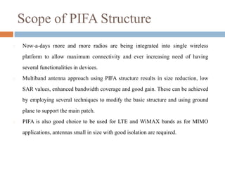
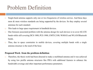


The research proposal by Naveen Kumar focuses on designing a multiband antenna using planar inverted-F antenna (PIFA) structures to meet the increasing demand for connectivity in mobile handheld devices. It outlines the need for compact antennas that support multiple wireless standards while improving gain and ensuring low specific absorption rate (SAR) values. The proposal emphasizes the advantages of PIFA in achieving size reduction and enhanced bandwidth coverage, addressing common challenges faced in mobile antenna design.