Downloaded 191 times
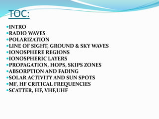
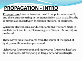


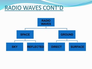
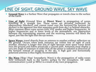
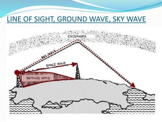
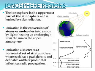
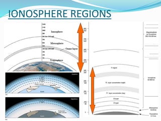
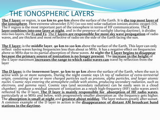
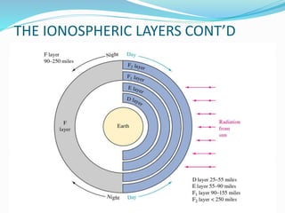
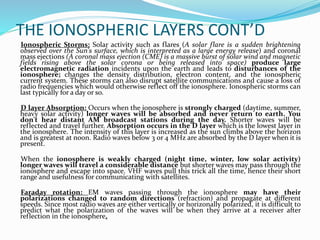

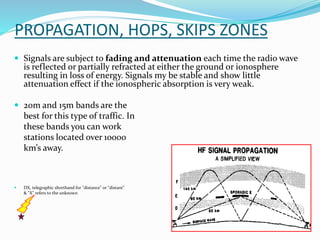
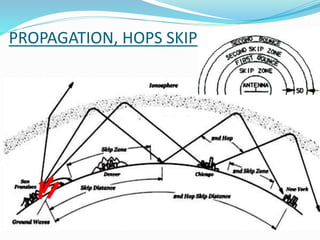
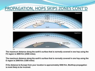
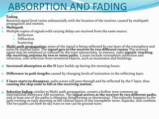
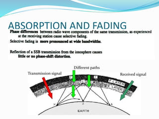
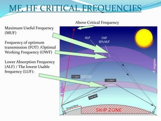
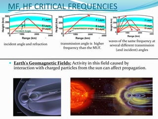

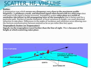
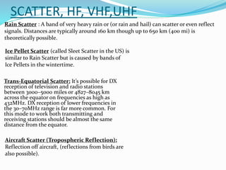


The document discusses various aspects of radio wave propagation. It explains that radio waves travel through the ionosphere and can be refracted back to Earth, allowing long distance communication. The ionosphere consists of several layers (D, E, F1, F2) that reflect radio waves of different frequencies depending on factors like solar activity and time of day. Radio propagation involves line-of-sight transmission as well as skywave propagation via reflection/refraction from ionospheric layers, which can allow signals to hop or skip distances beyond the horizon through multiple reflections. Absorption, fading, and noise affect signal strength over distance.