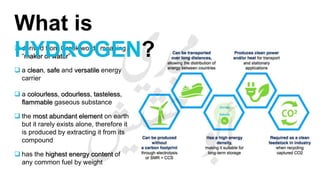
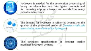
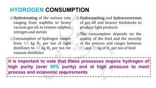
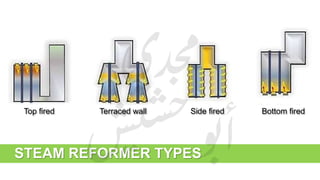
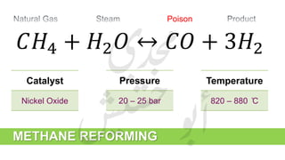
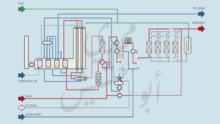
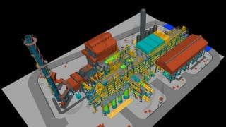
A full package presentation about Hydrogen Production Unit including an overview about steam reformers, combustion reaction, moods of heat transfer, draft systems, reactors, chemicals used in HPU, and types of compressors. Moreover, it describes the process description, process variables, and opens the way for some possible improvements which can be implemented to develop the unit performance.
1. Introduction reasons for purification, types of poisons, and typical systems
2. Hydrogenation
3. Dechlorination
4. Sulfur Removal
5. Purification system start-up and shut-down
Purpose
Key to good performance
Problem Areas
Catalysts, heat shields and plant up-rates
Burner Guns
Development of High Intensity Ring Burner
Case Studies
Conclusions
Steam Reformer Surveys - Techniques for Optimization of Primary Reformer Oper...Gerard B. Hawkins
Introduction
Background Radiation and Temperature Measurement
Reformer Survey Inputs
Other Troubleshooting Tools
Safety
Preparation
Onsite Data Collection
TWT Survey
Observation/Troubleshooting
Modelling and Analysis
Results/Outputs
Case Studies
Conclusions
Case Study 1
Case Study 2
Case Study 3
Conclusions
Look at two main types
Explain mechanisms
Explain prevention of cracking
Three main types
1 Carbon cracking
2 Boudouard carbon formation
3 CO reduction
Furnaces in Refinery and Petrochemicals
Process furnaces
Crude distillation unit
Reaction Heaters
Reformer Heater
Heater Performance objectives
Reasons to save Energy
Heater Types
Radiant section
Convection section
Crossover section
Burners
Calculation of an Ammonia Plant Energy Consumption: Gerard B. Hawkins
Calculation of an Ammonia Plant Energy Consumption:
Case Study: #06023300
Plant Note Book Series: PNBS-0602
CONTENTS
0 SCOPE
1 CALCULATION OF NATURAL GAS PROCESS FEED CONSUMPTION
2 CALCULATION OF NATURAL GAS PROCESS FUEL CONSUMPTION
3 CALCULATION OF NATURAL GAS CONSUMPTION FOR PILOT BURNERS OF FLARES
4 CALCULATION OF DEMIN. WATER FROM DEMIN. UNIT
5 CALCULATION OF DEMIN. WATER TO PACKAGE BOILERS
6 CALCULATION OF MP STEAM EXPORT
7 CALCULATION OF LP STEAM IMPORT
8 DETERMINATION OF ELECTRIC POWER CONSUMPTION
9 DETERMINATION OF THE TOTAL ENERGY CONSUMPTION OF THE AMMONIA PLANT ISBL
10 ADJUSTMENT OF ELECTRIC POWER CONSUMPTION FOR TEST RUN CONDITIONS
11 CALCULATION OF AMMONIA SHARE IN MP STEAM CONSUMPTION IN UTILITIES
12 CALCULATION OF AMMONIA SHARE IN ELECTRIC POWER CONSUMPTION IN UTILITIES
13 DETERMINATION OF THE TOTAL ENERGY CONSUMPTION OF THE AMMONIA PLANT OSBL
14 DETERMINATION OF THE TOTAL ENERGY CONSUMPTION OF THE AMMONIA PLANT
VULCAN Series VSG-Z101 Primary Reforming
Initial Catalyst Reduction
Activating (reducing) the catalyst involves changing the nickel oxide to nickel, represented by:
NiO + H2 <==========> Ni + H2O
Natural gas is typically used as the hydrogen source. When it is, the catalyst reduction and putting the reformer on-line are accompanied in the same step.
Catalytic Reactions in Catalytic Reforming
Catalytic Reforming Reactions
Sulfur Related Problems
Effects of Sulfur in Catalytic Reforming
Reactions in Catalytic Reforming
Catalytic Reforming Catalysts
Effect of Sulfur on Catalytic Reforming Catalysts
Catalytic Reformer Efficiency
VULCAN Sulfur Guards
VULCAN Sulfur Guards for Catalytic Reformers
VULCAN Guard Installation Protects Isomerization Catalysts
Liquid Phase vs Gas Phase: Relative Advantages
Liquid Phase Treating
Which active metal is best?
Thiophenes and Nickel Sulfur Guards
Sulfiding mechanisms with reduced metals
Thiophene adsorption on nickel
Advantages of Cu/Zn Over Nickel Sulfur Guards
Copper oxide vs Nickel
Nickel Sulfur Guards
Manganese Sulfur Guards
Hydrogen Plant Flowsheet - Effects of Low Steam RatioGerard B. Hawkins
Effect of Low Steam Ratio on the Steam Reformer
Effect of Low Steam Ratio on H T Shift & PSA
Effect of Low Steam Ratio on Gross Efficiency
Effect of Low Steam Ratio on Net Efficiency
Alternative schemes for improving heat recovery
Most modern ammonia processes are based on steam-reforming of natural gas or naphtha.
The 3 main technology suppliers are Uhde (Uhde/JM Partnership), Topsoe & KBR.
The process steps are very similar in all cases.
Other suppliers are Linde (LAC) & Ammonia Casale.
High Temperature Shift Catalyst Reduction ProcedureGerard B. Hawkins
High Temperature Shift Catalyst Reduction Procedure
The catalyst, as supplied, is Fe2O3. This reduces to the active form, Fe3O4, in the presence of hydrogen when process gas is admitted to the reactor.
1. The mildly exothermic reactions are:
3 Fe2O3 + H2 ========= 2 Fe3O4 + H2O
3 Fe2O3 + CO ========= 2 Fe3O4 + CO2
High level introduction
Mainstream syngas = steam reforming processes
Ammonia; methanol; hydrogen/HyCO
Town gas
Steam reforming; low pressure cyclic
Direct reduction iron (DRI)
HYL type processes; Midrex type processes
boiler accessories, basics of economizer, types of economizer, air preheater, types of air preheater, reheater, basics of superheater, types of superheater.
The paper is about utilizing the exhaust heat energy which is produced from the internal combustion engine of the vehicle to generate electricity by means turbine rotation. This system also helps to improve the performance, efficiency and emissions of the internal combustion engine.
Fossil fuel consumption in the recent years has been increasing and the burning of fossil fuel is said to be a major contributor towards global warming, acid rains, air, water and soil pollution, forest devastation and radioactive substances emissions. Besides the environment, the fossil fuel prices fluctuate considerably, usually going up and being very expensive in many countries.
Most importantly, the quantity of fossil fuels, like petroleum,natural gas, and coal can only decrease since they are non-renewable resources.
As a result many countries have been investing billions of dollars in new technologies and demand for sophisticated power supply options is greatly increased.
In a typical developed country as much as 40% of total fuel consumption is used for industrial and domestic space heating and process heating. Of this around one third is wasted.
Currently recovering low temperature heat which includes Industrial waste heat, geothermal energy, solar heat, biomass and so on could be a very critical and sustainable way to solve energy crisis. Utilising waste heats along with attempts for the use of renewable sources as low grade thermal heat has motivated us to develop a project based on ORC.
Secondary tar cleaning systems and technologiesAyisha586983
Physical separation process will continue to play a very important role for the successful commercial implementation of gasification.
Tar present in producer gas is removed mainly through wet or dry scrubbing, as it could be easily designed and applied depending on the specific need of any gasification process.
Even though in bed tar cracking is feasible in some cases removal of dust particles becomes necessary along with gas cooling
Slides for the eLearning course Separation and purification processes in biorefineries (https://open-learn.xamk.fi) in IMPRESS project.
Subject: Distillation
Subject: 0.2 Introduction to distillation.
Process plant equipment and their operations in petrochemical industrySavanSardhara
Process equipment is used in several applications like reaction purpose, steam power generation, pipelines, water treatment, salt water disposal etc., where chemical or mechanical methods are applied. Some examples of process equipment popularly used in these industries are pumps, boilers, distillation columns,
valves, vessels, filters, coolers, heat exchangers, compressors and piping. Each of these equipment is very important because of their indispensable usage in the working of a process.
Welcome to WIPAC Monthly the magazine brought to you by the LinkedIn Group Water Industry Process Automation & Control.
In this month's edition, along with this month's industry news to celebrate the 13 years since the group was created we have articles including
A case study of the used of Advanced Process Control at the Wastewater Treatment works at Lleida in Spain
A look back on an article on smart wastewater networks in order to see how the industry has measured up in the interim around the adoption of Digital Transformation in the Water Industry.
Courier management system project report.pdfKamal Acharya
It is now-a-days very important for the people to send or receive articles like imported furniture, electronic items, gifts, business goods and the like. People depend vastly on different transport systems which mostly use the manual way of receiving and delivering the articles. There is no way to track the articles till they are received and there is no way to let the customer know what happened in transit, once he booked some articles. In such a situation, we need a system which completely computerizes the cargo activities including time to time tracking of the articles sent. This need is fulfilled by Courier Management System software which is online software for the cargo management people that enables them to receive the goods from a source and send them to a required destination and track their status from time to time.
Industrial Training at Shahjalal Fertilizer Company Limited (SFCL)MdTanvirMahtab2
This presentation is about the working procedure of Shahjalal Fertilizer Company Limited (SFCL). A Govt. owned Company of Bangladesh Chemical Industries Corporation under Ministry of Industries.
TECHNICAL TRAINING MANUAL GENERAL FAMILIARIZATION COURSEDuvanRamosGarzon1
AIRCRAFT GENERAL
The Single Aisle is the most advanced family aircraft in service today, with fly-by-wire flight controls.
The A318, A319, A320 and A321 are twin-engine subsonic medium range aircraft.
The family offers a choice of engines
CFD Simulation of By-pass Flow in a HRSG module by R&R Consult.pptxR&R Consult
CFD analysis is incredibly effective at solving mysteries and improving the performance of complex systems!
Here's a great example: At a large natural gas-fired power plant, where they use waste heat to generate steam and energy, they were puzzled that their boiler wasn't producing as much steam as expected.
R&R and Tetra Engineering Group Inc. were asked to solve the issue with reduced steam production.
An inspection had shown that a significant amount of hot flue gas was bypassing the boiler tubes, where the heat was supposed to be transferred.
R&R Consult conducted a CFD analysis, which revealed that 6.3% of the flue gas was bypassing the boiler tubes without transferring heat. The analysis also showed that the flue gas was instead being directed along the sides of the boiler and between the modules that were supposed to capture the heat. This was the cause of the reduced performance.
Based on our results, Tetra Engineering installed covering plates to reduce the bypass flow. This improved the boiler's performance and increased electricity production.
It is always satisfying when we can help solve complex challenges like this. Do your systems also need a check-up or optimization? Give us a call!
Work done in cooperation with James Malloy and David Moelling from Tetra Engineering.
More examples of our work https://www.r-r-consult.dk/en/cases-en/
Democratizing Fuzzing at Scale by Abhishek Aryaabh.arya
Presented at NUS: Fuzzing and Software Security Summer School 2024
This keynote talks about the democratization of fuzzing at scale, highlighting the collaboration between open source communities, academia, and industry to advance the field of fuzzing. It delves into the history of fuzzing, the development of scalable fuzzing platforms, and the empowerment of community-driven research. The talk will further discuss recent advancements leveraging AI/ML and offer insights into the future evolution of the fuzzing landscape.
Event Management System Vb Net Project Report.pdfKamal Acharya
In present era, the scopes of information technology growing with a very fast .We do not see any are untouched from this industry. The scope of information technology has become wider includes: Business and industry. Household Business, Communication, Education, Entertainment, Science, Medicine, Engineering, Distance Learning, Weather Forecasting. Carrier Searching and so on.
My project named “Event Management System” is software that store and maintained all events coordinated in college. It also helpful to print related reports. My project will help to record the events coordinated by faculties with their Name, Event subject, date & details in an efficient & effective ways.
In my system we have to make a system by which a user can record all events coordinated by a particular faculty. In our proposed system some more featured are added which differs it from the existing system such as security.
Saudi Arabia stands as a titan in the global energy landscape, renowned for its abundant oil and gas resources. It's the largest exporter of petroleum and holds some of the world's most significant reserves. Let's delve into the top 10 oil and gas projects shaping Saudi Arabia's energy future in 2024.
Student information management system project report ii.pdfKamal Acharya
Our project explains about the student management. This project mainly explains the various actions related to student details. This project shows some ease in adding, editing and deleting the student details. It also provides a less time consuming process for viewing, adding, editing and deleting the marks of the students.
Cosmetic shop management system project report.pdfKamal Acharya
Buying new cosmetic products is difficult. It can even be scary for those who have sensitive skin and are prone to skin trouble. The information needed to alleviate this problem is on the back of each product, but it's thought to interpret those ingredient lists unless you have a background in chemistry.
Instead of buying and hoping for the best, we can use data science to help us predict which products may be good fits for us. It includes various function programs to do the above mentioned tasks.
Data file handling has been effectively used in the program.
The automated cosmetic shop management system should deal with the automation of general workflow and administration process of the shop. The main processes of the system focus on customer's request where the system is able to search the most appropriate products and deliver it to the customers. It should help the employees to quickly identify the list of cosmetic product that have reached the minimum quantity and also keep a track of expired date for each cosmetic product. It should help the employees to find the rack number in which the product is placed.It is also Faster and more efficient way.
Cosmetic shop management system project report.pdf
Hydrogen Production Unit
1.
2.
3. CONTENT
I. Hydrogen
II. Hydrogen for Refineries
III. Overview
a. Steam Reformers
b. Combustion
c. Moods of Heat Transfer
d. Draft Systems
e. Reactors
f. Chemicals for HPU
g. Types of Compressors
IV. HPU, ERC
V. Process Description
a. Feed Preparation
b. Steam Reforming
c. Product Purification
d. Final Product
e. Steam Production
VI. Process Variables
VII. Possible Improvements
6. derived from Greek words meaning
“maker of water”
a clean, safe and versatile energy
carrier
a colourless, odourless, tasteless,
flammable gaseous substance
the most abundant element on earth
but it rarely exists alone, therefore it
is produced by extracting it from its
compound
has the highest energy content of
any common fuel by weight
What is
HYDROGEN?
9. Hydrogen is needed for the conversion processing of
heavy petroleum fractions into lighter products and
for removing sulphur, nitrogen and metals from many
petroleum fractions
The demand for hydrogen in refineries depends on the
quality of the processed crude oil (heavier crude oils
necessitates more demand for hydrogen)
The stringent specifications of product quality
increases hydrogen demand
10. HYDROGEN CONSUMPTION
Hydrotreating of the various cuts
ranging from naphtha to heavy
vacuum gas oil, to remove sulphur,
nitrogen and metals
Consumption of hydrogen ranges
from 0.6 kg H2 per ton of light
distillates to 10 kg H2 per ton for
vacuum distillates
Hydrocracking and hydroconversion
of gas oil and heavier feedstocks to
produce light products
The consumption depends on the
quality of the feed and the severity
of the process and ranges between
15 and 35 kg of H2 per ton of feed
it is important to note that these processes require hydrogen of
high purity (over 99% purity) and at high pressure to meet
process and economic requirements
14. FURNACE
Furnace walls, floor, and ceiling are lined with a
material that reduces heat losses and reflects
heat back to the tubes (refractory lining)
Inside the stack is a damper which controls the
flow of flue gases out of the furnace, thus
controls the furnace draft
15. • Radiation section
bulk of the total heat transferred occurs
• Convection section
surface area required is controlled by film resistance of the flue-gas side
• Tubes
carry the process fluid, or flow through the furnace
• Burners
where combustion occurs
COMPONENTS
16.
17. COMBUSTION
• Combustion: a chemical reaction that produces heat
• It requires: fuel, oxygen, and a source of ignition
• Two types of combustion reaction:
Complete
Incomplete
18. Complete Combustion Incomplete Combustion
• CH4 + 2 O2 → CO2 + 2 H2O + Heat
• Happens with enough oxygen (excess air)
• One pound of carbon releases 14,100 BTU’s
• If oxygen is not enough, some of the carbon atoms unite
with one atom of oxygen to form carbon monoxide (CO)
instead of carbon dioxide (CO2)
• One pound of carbon releases 4,000 BTU’s
• Generate unburned fuel which poses fire, or explosion
hazard in the furnace
COMPLETE VS. INCOMPLETE
COMBUSTION
19.
20. • The process of heat transfer through the material due to the
temperature difference
• Heat flow from high to low temperature
• Affected by:
thermal conductivity (Material)
temperature difference between the
metal surfaces
area of heat transfer
material thickness
CONDUCTION
21. CONVECTION
• Heat transferred between solid surface and adjacent liquid or
gas in motion
• Two types:
Forced convection
Natural convection
22. RADIATION
• Energy emitted by matter in the form of electromagnetic waves
• Heat transfer without contact
• Unlike conduction and convections, does not require a medium
• Thermal radiation emitted by bodies due to their temperatures
23.
24. DRAFT SYSTEMS
• Draft: buoyant energy created by hot gases as they rise through
the furnace
• Draft systems:
a. Natural Draft
b. Forced Draft
c. Induced Draft
d. Balanced Draft
25. Natural Draft Forced Draft Induced Draft Balanced Draft
• Maintained by the
natural, upward flow of
hot gases
• Flue gases are replaced
with cool air
• Draft is controlled by the
damper’s position
• Combustion air is
supplied by a fan
• Permits steady control
of the air at the burners
• Draft is produced by
discharging the flue gas
with a fan
• The fan is located
between the convection
section and the stack
• Two fans
• One fan (forced)
supplies air to the
burners
• Other fan (induced)
discharges flue gas from
the burners
• Allows greater control
DRAFT SYSTEMS
29. REACTORS
• Inlet distributor: inlet baffles used to prevent direct
impingement on the reactor bed for high inlet velocities
flows
• Debris collector:
to provide an increased area for fluid flow
to collect trash and any “tramp material” which can be
caught in the baskets
not required for clean feed streams
• Inert balls: inert ceramic balls (usually alumina) used to
protect the catalyst bed from direct impingement on the
inlet feedstock stream
a screen is sometimes included below the layer
of inert ceramic material to prevent the more
dense balls from sinking into the catalyst bed
during normal operation
30. REACTORS
• Catalyst separation screens (top of bed):
keeps the ballast out of the catalyst bed
not attached to the reactor and is free to settle with the bed during the run
• Catalyst separation screens (bed support): a fine screen whose opening is less
than the catalyst size, sometimes used between the catalyst and the inert support
do not affect the total reactor pressure drop
designed to have a maximum open surface area
prevents catalyst pieces and fines generated during normal operation from
reaching the outlet
• Catalyst bed supports: a layered fill of high purity alumina directly beneath the
catalyst (twice the catalyst size)
31. REACTORS
• Outlet collector: used whenever an inert fill support material is used
keep the flow evenly distributed across the bottom of the reactor, otherwise the
flow would tend to move toward the outlet nozzle before passing through the
whole of the bed
• Catalyst unloading connections: filled out with inert support balls and used as a
drop out nozzle
has a removable length which projects into the vessel
the extended pipe length reaches up to the catalyst bed
• Void space:
allows access to the top of the reactor
depends on reactor diameter and applied internals
avoids direct impingement of the inlet streams onto the packed surface if no other
internals are used
32.
33. • Injection point: Hydrogenator
• Dimethyl Disulfide (DMDS) is the most commonly used chemical for sulfiding hydrotreating and
hydrocracking catalysts. These hydroprocessing catalysts contain metal oxides that must be
converted to the active metal sulfide before they will promote desulfurization and denitrification
reactions on hydrocarbon feeds
• Applications:
Hydrodesulfurisation catalyst activation
Hydrotreatment catalyst activation
Hydrocracking catalyst activation
Propane Dehydration
Steam cracking
• Advantages of sulfiding with DMDS are:
lowest total cost
high sulfur content (68%)
low decomposition temperature
by-products will not cause premature coking
chosen by catalyst manufactures for activity testing and catalyst development
DMDS
34. • Injection point: Steam Drum
• it works as an anti-scalant since phosphate react with calcium hardness to create suspended solids
(which is easier to discharge via blowdown) in order to prevent any calcium carbonate (CaCO3)
/calcium silicate (CaSiO3) scale
• it also can act as pH adjuster. A flexible boiler pH adjuster (TSP to increase pH, DSP to maintain
pH, or MSP to even decrease pH)
PHOSPHATE
• even in case of high pressure boiler which require no
phosphate because strict electrical conductivity both in boiler
and steam - when pH is decreasing, phosphate is still
frequently being used as temporary-first aid kit
35. • Injection point: Deaerator (Degasser)
• known as an oxygen scavenger (oxygen absorber) is a material in which one or more reactive
compounds can combine with oxygen to reduce or completely remove oxygen in fluids and enclosed
packaging
• the purpose of deoxidant is to limit the amount of oxygen available for deteriorative reactions that can
lead to reduce functionality of many types of products;
DEOXIDANT
to prevent oxygen-induced corrosion, an oxygen scavenger can be used as
a corrosion inhibitor in applications like oil and gas production
installations and seawater system, thus increasing their service life
• Carbohydrazide is used in our plant. Its chemical formula is
OC(N2H3)2. It is a white, water-soluble solid which gives
outstanding protection from oxygen, plus feed water and boiler
system passivation.
38. RECIPROCATING FEED COMPRESSOR
• A positive-displacement machine that uses a
piston to compress a gas and deliver it at high
pressure.
• Used where high compression ratios (ratio of
discharge to suction pressures) are required per
stage without high flow rates, and the process
fluid is relatively dry.
• Used for typical gases including;
air for compressed tool and instrument air systems
hydrogen, oxygen, etc. for chemical processing
light hydrocarbon fractions in refining
various gases for storage or transmission
other applications
39. RECIPROCATING FEED COMPRESSOR
• Has a similar design to an internal combustion engine; it even looks
similar. There is a central crankshaft that drives anywhere from two to
six pistons inside cylinders.
• Crankshaft is generally driven by an external motor. This motor can be
electric or internal combustion (it determines the total horsepower of
the compressor).
• As the pistons draw back, gas is injected from an intake valve in the
compressor. This gas is injected into the cylinders of the pistons, and is
then compressed by the reciprocating action of the pistons. The gas is
then discharged either to be used immediately by a pneumatic
machine, or stored in tanks. However, the gas must be stored or used
directly from the compressor to prevent it from losing its pressurization.
42. CASE 1 (90,000 Nm3/h)
feedstock is natural gas
and the same natural gas
is used as make-up fuel in
the reformer furnace
58 t/h export steam
CASE 2 (100,000 Nm3/h)
feedstock is Purge gas
coming from the HCU and
natural gas is added to
meet the plant capacity; in
addition to a H2-rich stream
coming from the CCR
60 t/h export steam
DESIGN CAPACITY
47. The process is made of the following basic steps:
• Feed compression
• Feed pre-treatment (hydrogenation/desulphurization)
• Steam reforming
• Conversion of carbon monoxide to carbon dioxide
• Purification of hydrogen by pressure swing adsorption
• Generation of steam from imported demineralized water using
waste heat
PROCESS DESCRIPTION
50. FEED PREPARATION
• The feed to the steam reforming unit is a stream of natural gas mainly consists of
CH4
• NG is supplied from the network at a pressure of 18 bar (a low pressure for NG
processing to Hydrogen)
• This stream may contain poisons to the nickel catalyst (poisons are sulphur
compounds such as hydrogen sulphide and mercaptans, and halogenated
compounds such as chlorides)
Feed preparation involves compression from 18 to 28 bar and hydrogenation of organic sulphur
and chloride into H2S and HCl respectively. H2S is then adsorbed in a ZnO bed. The treated feed
should contain 0.1 ppm sulphur or less, and the chloride content should be limited to 0.5 ppm.
53. It consists of two basic steps:
1. HYDROGENATION - Hydrogenolysis of organic sulphur compounds to
hydrogen sulphide over a cobalt molybdenum catalyst (inside a
hydrogenator)
2. DESULPHURERISATION - Adsorption of the hydrogen sulphide on a
zinc-oxide catalyst (inside lead-lag desulphurisers)
HYDRODESULPHERISATION
54. • takes place over a large range of temperatures and pressures
• organic sulphur compounds is converted into hydrogen sulphide to be easily
removed by chemical adsorption over a zinc oxide catalyst
• hydrogenolysis reaction;
HYDROGENATION
R𝑆 + 2𝐻2 ↔ 𝐻2 𝑆 + 𝑅𝐻2
• exothermic reaction (heat produced depends on type and content of the sulphur
compounds
• rate of hydrogenolysis rises with temperature increase (T is maintained at 340 -
380 ֯C)
• for a given type of sulphur compound, the rate of hydrogenolysis increases by
increasing molecular weight
55. CoMox (Cobalt Molybdenum):
Extruded shape
Support material; high surface alumina
38.1 m3
3 years life time
Properties:
Catalyst activities were measured in the temperature range 573
- 653 K (300 - 380 ̊C)
γAl2O3 as a support is favored due to its mechanical properties,
moderately low cost and its capability to provide high dispersion
of the active metal phase
HYDROGENATOR CATALYST
CoMox catalysts are preferred where desulpherisation is the chief requirement, while NiMox
catalysts are preferred for removal of nitrogen- containing compounds and hydrogenation of
aromtics is required
56. • rate of desulpherisation increases by increasing H2 partial pressure and reducing HC
partial pressure
this effect decreases with a decreased molecular weight
• Desulpherisation reaction;
DESULPHERISATION
𝑍𝑛𝑂 + 𝐻2 𝑆 ↔ 𝑍𝑛𝑆 + 𝐻2 𝑂
• adsorption of hydrogen sulphide ceases when the oxide becomes fully converted (catalyst
must be replaced)
• overall rate of adsorption depends on:
type and concentration of the sulphur compounds (≤ 300 ppm according to best practice)
gaseous space velocity (determined by the throughput and lifetime required)
reaction temperature (≤ 400 ֯C)
57. Zinc oxide , ZnO:
Spheres shape
32 m3 (each bed)
1.5 year/bed Life time
Properties:
pure ZnO is a white powder, relatively soft material
has high refractive index, high thermal conductivity,
binding, antibacterial and UV-protection properties
has high heat capacity and heat conductivity, low thermal
expansion and high melting temperature
DESULPHERISERS CATALYST
58.
59. • Steam reforming reaction takes place at:
Low pressures of 20 – 25 bar
High temperatures of 820 – 880 ˚C
• Steam is used in:
decreasing partial pressure of the natural gas
converting most of the coke lay down on the catalyst to CO and CO2
controlling temperature
STEAM REFORMING
60. • Catalyst filled tubes
6 rows, 48 tube per row
• Top fired burners
7 rows, 14 burner per row
• Tubes connected to manifolds
top and bottom
• Convection section, flue gas duct and stack
6 heat exchangers
STEAM REFORMER
63. The steam reforming of methane consists of
two reversible reactions:
strongly endothermic reforming reaction
moderately exothermic water-gas shift reaction
STEAM REFORMING THERMODYNAMICS
64. STEAM REFORMING THERMODYNAMICS
Due to its endothermic character,
reforming is favored by high
temperature. Also, because
reforming is accompanied by a
volume expansion, it is favored by
low pressure. In contrast, the
exothermic shift reaction is
favored by low temperature, while
unaffected by changes in
pressure.
Increasing the amount of steam
will enhance the CH4 conversion,
but requires an additional amount
of energy to produce the steam. In
practice, steam to carbon ratios
(S/C) around 2.5 – 5 are applied.
This value for S/C will also
suppress coke formation during
the reaction.
65. Nickel oxide, NiO:
4 Holes shape
Support material; alumina, magnesia and calcium oxide
38.1 m3
3 years life time
Properties:
economically effective
has a low pressure drop
high surface-area-to-volume ratio (preferred because of diffusion
limitations due to high operating temperatures)
very sensitive to even low concentrations of certain impurities
(sulphur, arsenic, halogens, copper, and lead)
STEAM REFORMER CATALYST
69. CONVERSION OF CO TO CO2
• Conversion of CO to CO2 with steam and suitable catalysts
• Occurs in one-stage shift converter
• CO conversion reaction;
𝐶𝑂 + 𝐻2 𝑂 ↔ 𝐶𝑂2 + 𝐻2 + 𝐻𝑒𝑎𝑡
• Reversible exothermic reaction
• Equilibrium independent of pressure (equimolar reactants)
• High conversions favored at low temperatures and high
excess steam
70. Mixture of Fe3O4 (base), Cr2O3, and CuO:
Pellets shape
44 m3
3 years life time
Properties:
Fe3O4; economical, stability and the ability to withstand
considerable quantities of impurities without being poisoned
Cr2O3; increases the useful life of the catalyst
CuO; increases the activity at lower temperatures and at
reformer lower S/C ratios
HTS CATALYST
71. PURIFICATION OF H2 BY PSA
A pressure swing adsorption (PSA) unit is
used to selectively separate CO2 through
membranes, thus purifying the hydrogen rich
product gas stream.
72.
73. PRESSURE SWING ADSORPTION (PSA)
• The reformed gas from the shift converter which contains 65–70 vol% hydrogen can be
purified by adsorption. The process produces a higher purity hydrogen stream (99.9%).
• PSA is a cyclic process involving the adsorption of impurities (CO, CO2, CH4 and N2)
from a hydrogen-rich gas stream at high pressure on a solid adsorbent such as a
molecular sieve. The operation is carried out at room temperature and at the reformed
gas pressure of 20–25 bar. Several adsorption vessels (adsorbers) are employed as
shown in the next figure. The feed gas is switched from one adsorption vessel to another.
While adsorption takes place in one vessel, the adsorbent in another vessel is being
regenerated.
74.
75. PSA – STEP #1
Adsorption takes place in a fresh adsorber producing high
purity gas. The impurities are adsorbed onto the internal
surfaces of the adsorbent bed. When this adsorber reaches
its adsorption capacity and no more impurities can be
removed, it is taken off-line, and the feed is switched to
another fresh adsorber.
76. PSA – STEP #2
To recover the hydrogen trapped in the adsorbent void
spaces in the adsorber, the adsorber is depressurised from the
product side in the same direction as the feed flow direction
(cocurrent), and high-purity hydrogen is withdrawn. The
hydrogen is used internally in the system to repressurise and
purge other adsorbers.
77. PSA – STEP #3
The bed is then partly regenerated by
depressurising in a countercurrent flow of gas from
other beds, and the desorbed impurities are rejected
to the PSA off-gas.
78. PSA – STEP #4
The adsorbent is then purged with high-purity
hydrogen (taken from another adsorber on cocurrent
depressurisation) at constant off-gas pressure to
further regenerate the bed.
79. PSA – STEP #5
The adsorber is then repressurised with hydrogen prior to
being returned to the feed step. The hydrogen for
repressurisation is provided from the cocurrent depressurisation
and with a slipstream from the hydrogen product. When the
adsorber has reached the adsorption pressure, the cycle has
been completed, and the adsorber is ready for the next
adsorption step.
80.
81. FINAL PRODUCT
The final product gas is typically 99.9% hydrogen
The higher hydrogen purity is beneficial to the
downstream hydrotreating and hydrocracking units
since it;
increases the hydrogen partial pressure
lowers compression costs
lowers the recycle flow
increases catalyst life
82.
83. STEAM PRODUCTION
The steam reforming process make use of
high reaction temperatures in the reformer to
produce high pressure steam by cooling
down process gas. The process gas from the
steam reformer is cooled down in a process
gas boiler. The sensible heat is utilized for the
generation of HP steam.
84. STEAM PRODUCTION
• A steam drum is a standard feature of a water-tube boiler. It is a reservoir of
water/steam at the top end of the water tubes. The drum stores the steam generated in
the water tubes and acts as a phase-separator for the steam/water mixture. The
difference in
Process Gas Boiler and Steam Drum
• Steam drum is mounted on top of the
process gas boiler and is supported by
down comers and risers. Erection costs
are low due to shop assembly.
densities between hot and cold water
helps in the accumulation of the "hotter"-
water/and saturated-steam into the steam-
drum.
86. 1. Feed Type
2. Catalyst Activity
3. Reaction Pressure
4. Steam to Carbon Ratio
5. Tube Skin Temperature
6. Reformer Inlet Temperature
7. Reformer Outlet Temperature
8. Liquid Hourly Space Velocity (LHSV)
OPERATING PARAMETERS VARIATION FOR
REFORMER
87. FEED TYPE
Light hydrocarbons constitute suitable feed to the
steam reformer as shown in the next table.
The light hydrocarbons in the feed are first converted
to methane. Then the methane–steam reforming
reactions take place. A methane rich feed gives
higher hydrogen purity.
88. CATALYST ACTIVITY
Higher catalyst activity favors the reforming reaction.
Catalyst is poisoned by sulphur, chloride and arsenic.
The catalyst is poisoned by sulphur due to slippage of
mercaptan and hydrogen sulphide along with the feed.
There is also the possibility of catalyst poisoning due to
sulphate carry-over with water mist in steam and
dissolved H2S in impure boiler feed water. The catalyst
can also be poisoned by carry-over of arsenic present
in ZnO. Chlorine and phosphorous poisoning can
come from boiler feed water.
As the steam reforming reaction decreases over time due to catalyst poisoning, the hydrogen
purity can be maintained by increasing the furnace outlet temperature and increasing the steam
to carbon ratio.
89. REACTION PRESSURE
In the reforming reaction, the volume of the products is three times
higher than the volume of reactants. Therefore, at a fixed temperature
and steam to carbon ratio, lower pressure favors the equilibrium of the
reaction. The design outlet pressure of the reformer is in the range
20–25 bar. The operating pressure of the heater is not fixed locally.
This pressure is governed by
the unit system pressure set
by the pressure required at
the hydrogen product export
header.
90. STEAM TO HYDROCARBON RATIO (ST/HC)
Ratio of moles of steam to moles of carbon in the
reformer feed (obtained by dividing the molar flow
rates of steam and feed).
Reformer feed must contain sufficient steam to avoid
thermal cracking of the hydrocarbons and coke
formation.
An excess of steam (over the stoichiometric ratio) is
usually used; the higher the steam to carbon ratio, the
lower the residual methane will be for a given reformer
outlet temperature (hence, less fuel energy is required
in the furnace).
Design steam to carbon is typically 3.0 with a range
between 2.5 and 5.0.
91. REFORMER INLET TEMPERATURE
Since the reforming reaction is endothermic, it is favored by high temperature.
Reformer catalyst tube inlet temperature is maintained at 540–580 ˚C; the
hydrocarbon steam feed is preheated by the hot flue gas in the waste heat
recovery (convection) section of the furnace.
A higher inlet temperature decreases the amount of fuel required to supply heat to
the reaction tubes and decreases the number of tubes and the size of the furnace.
Utilization of the hot flue gas to reheat the feed increases the energy efficiency of
the process and decreases the steam generation in the waste heat recovery
section.
92. REFORMER OUTLET TEMPERATURE
The upper limit of the outlet temperature is governed by the design
maximum tube skin temperature which is 1093 ˚C.
High-temperature operation is not necessarily the most economic
method taking into consideration the amount of fuel to be burned for
an increase in purity. The reformer has been designed for normal
operation at outlet temperature in the range of 820–880 ˚C.
The lower feed gas rate will lower the required reformer outlet
temperature for the same hydrogen purity. Similarly, the higher steam
to carbon ratio will lower the required reformer outlet temperature for
the same hydrogen purity.
Outlet temperature is the most important process variable that determines the purity of the hydrogen product.
The higher the reformer outlet temperature the lower will the residual methane be (higher hydrogen purity) for a
given feed rate and steam to carbon ratio.
93. TUBE SKIN TEMPERATURE
A portable infrared radiation optical
pyrometer is used to measure the tube
skin temperature.
Measurements are done at different
heights of the catalyst tubes and from
many directions to in order to achieve an
accurate temperature profile of each
tube.
Skin temperatures change with capacity and process
variables.
94. LIQUID HOURLY SPACE VELOCITY (LHSV)
Lower space velocity favors the reaction as
residence time increases (however, this
leads to reduce output gas).
𝐿𝐻𝑆𝑉 =
𝑡𝑜𝑡𝑎𝑙 𝑣𝑜𝑙𝑢𝑚𝑒𝑡𝑟𝑖𝑐 𝑓𝑒𝑒𝑑 𝑓𝑙𝑜𝑤 𝑟𝑎𝑡𝑒 𝑡𝑜 𝑡ℎ𝑒 𝑟𝑒𝑎𝑐𝑡𝑜𝑟
𝑡𝑜𝑡𝑎𝑙 𝑐𝑎𝑡𝑎𝑙𝑦𝑠𝑡 𝑣𝑜𝑙𝑢𝑚𝑒
=
𝑣˳
𝑉
=
1
𝜏
= ℎ−1
LHSV measures liquid volumetric rate at 60 ̊F or 75 ̊F (15.56 ̊C or 28.89 ̊C)
96. •Development work is focused on new steam reforming catalysts with higher activity and lower pressure
drops. The catalyst will also be less resistant to heat transfer, resulting in more heat to the reaction at a
lower tube skin temperature and a closer approach to equilibrium conversion.
New improved tube materials with a design skin temperature up to 1050 ˚C are utilized in reforming
New reformer designs with smaller tube diameters have a smaller size but twice the heat flux of older
New shift conversion catalysts operating at lower steam to carbon ratios and lower
being developed.
•Modern plants are designed with reforming temperatures above 900 ˚C and steam to carbon
ratios below 2.5. The new developments include utilizing the more energy-efficient side-fired
reforming furnace and using medium temperature shift catalyst.
PROCESS DEVELOPMENTS