Downloaded 1,387 times


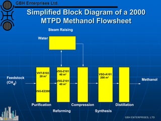


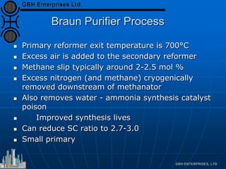
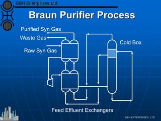


The document discusses various aspects of ammonia production processes including: 1) Simplified block diagrams of typical ammonia, methanol, and hydrogen production plants showing the main process units. 2) Modern conventional ammonia plant flowsheets have the same main process steps but differ in equipment designs between vendors. 3) Other flowsheet options for ammonia production including the Braun Purifier process, ICI AMV, ICI LCA, dual pressure Uhde process, and Linde LAC process. 4) Additional process modifications and options such as gas turbine drives, pre-reformers, heat recovery techniques, synthesis gas driers, and booster converters.


![Kbr[1] report](https://cdn.slidesharecdn.com/ss_thumbnails/kbr1-160104072613-thumbnail.jpg?width=640&height=640&fit=bounds)


