Download as PDF, PPTX
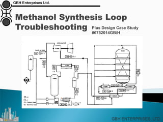
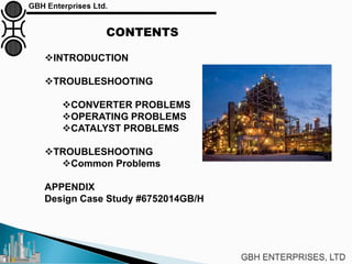
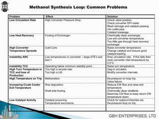
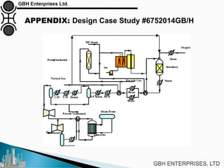


The document is a case study on common problems in a methanol synthesis loop, highlighting issues related to converters, operating conditions, and catalyst performance. Key topics include rapid catalyst deactivation, temperature excursions, and various operational challenges such as fouling and leaks. Solutions and troubleshooting methods are also discussed to improve efficiency and minimize production loss.


![Getting Started with Apache Spark: Big Data Made Simple [Free Meetup]](https://cdn.slidesharecdn.com/ss_thumbnails/apachesparkgettingstarted-260203175547-8361bcc3-thumbnail.jpg?width=640&height=640&fit=bounds)


