SlideShare a Scribd company logo
Steam methane reformers
33 www.nitrogenandsyngas.com Nitrogen+Syngas 359 | May-June 2019
syngas
syngas
syngas cooling
syngas cooling
boiler feed water
boiler feed water
reformer
reformer
pre-reformer
pre-reformer
hydro-
desulphurisation
pre-treatment
hydro-
desulphurisation
pre-treatment
tail gas
tail gas
natural
gas
natural
gas
H2
H2
heat
recovery
heat
recovery
process steam
process steam
flue gas
flue gas HP steam
HP steam
flue gas
flue gas
fuel gas
fuel gas
Fig. 1: 
Steam methane reforming
Source: Sandvik
catalyst tubes
catalyst tubes
manifolds
manifolds
pigtails
pigtails
Fig. 2: 
Steam methane reformer
Source: Sandvik
S
team reformers used in hydrogen,
ammonia and methanol plants
are complex, energy intensive and
expensive. By nature their design is often
aggressive, due to the need for harsh oper-
ating conditions and specialty materials.
A failure in the primary reformer typically
has large financial implications, often run-
ning into millions of dollars, as significant
downtime is incurred alongside the costs
of tubes, engineering and catalyst.
The basics
In a conventional steam reforming process
(Fig. 1) hydrogen and mixture of CO/CO2 are
produced by reacting methane with steam
over a nickel catalyst at high temperatures.
The catalyst is contained in the reformer
tubes, which are located in a box type fired
furnace (Fig. 2) that provides the large endo-
thermic heat of reaction.
The basic reactions of the steam
reforming of methane are expressed by the
following chemical equations.
Desired reactions:
CH4 + H2O → CO + 3H2  (1)
CO + H2O → CO2 + H2  (2)
CH4 + CO2 → 2CO + 2H2  (3)
Unwanted reactions:
2CO → C + CO2  (4)
CH4 → C + 2H2  (5)
CO + H2 → C + H2O  (6)
Reaction (1) is known as steam methane
reforming, while reaction (2) is referred to
as the water gas shift reaction. Both reac-
tions are reversible and approach equilib-
rium. In addition to the desired reactions (1)
and (2), other side reactions (3, 4, and 5)
are under certain conditions also possible.
Selection of suitable catalyst and appropri-
ate operating conditions will promote reac-
tions (1) and (2) and suppress reactions
4 to 5. Reaction (3) takes place in steam
reformers where CO2, available downstream
of the CO2 removal section, is recycled back
to the reformer in order to increase CO for-
mation in the syngas (methanol, oxo syngas
production).
The conversion is favoured by a high
steam to carbon ratio (in excess of the
stoichiometric quantity), high outlet tem-
perature, low pressure and high catalyst
activity. There are restrictions and limita-
tions for maximum conversion:
Controlling the stresses
of the primary reformer
Risk associated with the primary reformer is highly dependent on its operation. In this article we
look at common problems associated with catalyst tubes, pigtails, operating close to material
limits etc. and discuss latest practices and new materials to prevent these issues and allow
plants to run at maximum output without unplanned outages.
Steam methane reformers
Nitrogen+Syngas 359 | May-June 2019 www.nitrogenandsyngas.com 33
Fig. 3: 
Geometry of reformer furnaces
Top-fired furnace
Side-fired furnace
Terrace wall-fired furnace
Bottom-fired furnace
Source:
IKR
Richter
l A steam to carbon ratio that is too high
will make the process less energy effi-
cient, large quantities of excess steam
have to be condensed and high volumet-
ric steam flow will increase the equip-
ment cost. Low steam to carbon ratio
will improve the energy efficiency, but
can form carbon in the catalyst pores
and other undesirable byproducts.
l An operating temperature that is too
high poses problems of heat transfer
and lowers the mechanical strength
of the reformer tube material (metal
temperatures up to 960°C under pres-
sure of about 35 bar). Low operating
temperature reduces the conversion,
but sometimes this offers an attractive
possibility for conversion completion
under optimum conditions downstream
the primary reformer;
l An operating pressure that is too low
increases the cost of equipment and
makes the reforming process inef-
ficient, as it is always necessary to
compress the produced syngas at
higher pressures for further processing
(purification and synthesis). There are
mechanical limits for higher reforming
pressures, but in general higher reform-
ing pressure reduces the overall operat-
ing and investment cost.
l Catalyst with too high activity could at
first improve the conversion rate, but
because of its sensitivity, it may easily
lose activity due to feedstock impurities,
or because of maloperation. Small size
catalyst in a given total reformer tube
volume will present a higher surface to
catalyst volume ratio and thus a higher
conversion rate and a better approach to
equilibrium, but also gives a higher pres-
sure drop. Loss of activity may lead to
reformer tube overheating, as reduced
conversion means less heat absorption
for the endothermic reforming reaction.
Primary reformer configurations
Several configurations of reforming fur-
naces are in use today, characterised
mainly by the disposition and position of
the burners. The most common types are
top-fired, side-fired and terraced wall-fired
reformers. Bottom-fired reformers are not
very common in modern syngas plants.
Fig. 3 shows the overall geometry of these
reformer furnaces.
The top-fired reformer uses multi-
ple rows of reformer tubes with burners
located in the arch on each side of the
tubes. The heat to the reformer tubes
is supplied by the radiating products of
combustion. The main advantage of this
configuration is the few burners relative to
the reformer tubes, the higher radiant effi-
ciency, the presence of the high heat flux
zone in the “cold” inlet of the feedstock
and the very large reformer tube number
which can be accommodated in one radi-
ant box. The main disadvantages are the
limitation in the heat input control and the
hot operating level at the top.
The side-fired reformer has multiple
radiant wall burners along both side walls
and one row of reformer tubes in the mid-
dle of the box. The heat to the reformer
tubes is emitted from the radiant walls.
The main advantage is the uniform heat
distribution and the very good heat input
control. Disadvantages are the large num-
ber of burners required, the lower radi-
ant efficiency and the size limitation of
the fired box (single box for 100 to 150
reformer tubes).
The terraced wall type, developed by
Foster Wheeler may be regarded as an
intermediate between the side-fired and
bottom-fired reformers. The reformer has
inclined walls with several terraces on which
upward firing burners are installed. This
unique burner positioning makes it possible
to adjust the heat flux in each zone.
Bottom-fired furnaces have a rather con-
stant heat flux profile along the reformer
tube with high metal temperatures on the
outlet side.
The high heat flux and the high reformer
tube skin temperature at the upper part of
the reformer is the main characteristic of
top fired reformers. In the side-fired and
the terraced wall reformer the heat flux
along the reformer tube and the conversion
are more uniform. In Fig. 4 the respective
profiles of reformer tube skin temperature,
heat flux, and methane conversion are
shown for the two most common reformer
furnaces.
In a conventional reforming process
only 40% of furnace duty is absorbed by
the endothermic heat of reaction. About
35% is recovered in the form of waste
heat export steam, by utilising part of the
Steam methane reformers
33 www.nitrogenandsyngas.com Nitrogen+Syngas 359 | May-June 2019
potential production
10
10 20
20 30
30 40
40 50
50 60
60 70
70 80
80 90
90 100
100
max tubeskin temp
max tubeskin temp
heat flux
heat flux
process gas temp
process gas temp
methane conversion
methane conversion
process gas pressure
in
in out
out
heated tubelength, %
Top-fired reformer profiles
0.14
0.12
0.10
0.08
0.06
0.04
0.02
0.00
0.14
0.12
0.10
0.08
0.06
0.04
0.02
0.00
1.0
0.8
0.6
0.4
0.2
0.0
1.0
0.8
0.6
0.4
0.2
0.0
27
26
25
24
27
26
25
24
1,300
1,200
1,100
1,000
900
800
700
600
500
400
300
200
1,300
1,200
1,100
1,000
900
800
700
600
500
400
300
200
pressure,
bar
pressure,
bar
temperature,
°C
temperature,
°C
heat
flux,
10
3
kJ/m
2
s
heat
flux,
10
3
kJ/m
2
s
CH4
conv.
CH4
conv.
10
10 20
20 30
30 40
40 50
50 60
60 70
70 80
80 90
90 100
100
max tubeskin temp
max tubeskin temp
heat flux
heat flux
process gas
temp
process gas
temp
methane conversion
methane conversion
process gas
pressure
process gas
pressure
in
in out
out
heated tubelength, %
0.14
0.12
0.10
0.08
0.06
0.04
0.02
0.00
0.14
0.12
0.10
0.08
0.06
0.04
0.02
0.00
1.0
0.8
0.6
0.4
0.2
0.0
1.0
0.8
0.6
0.4
0.2
0.0
17
16
15
17
16
15
1,300
1,200
1,100
1,000
900
800
700
600
500
400
300
200
1,300
1,200
1,100
1,000
900
800
700
600
500
400
300
200
pressure,
bar
pressure,
bar
temperature,
°C
temperature,
°C
heat
flux,
10
3
kJ/m
2
s
heat
flux,
10
3
kJ/m
2
s CH4
conv.
CH4
conv.
Side-fired reformer profiles
START
cracks 30%
from inner wall
START
cracks 30%
from inner wall
GROWTH
cracks grow to
break inner bore
GROWTH
cracks grow to
break inner bore
FAILURE
cracks progress
to outer wall
FAILURE
cracks progress
to outer wall
Fig. 5: Progression of creep through a reformer tube
Source: IKR Richter
Source: IKR Richter
Fig. 4: 
Reformer furnace temperature and heat flux profiles
latent heat of the syngas for CO2 removal
and by preheating feed stock-combustion
air or boiler feed water in the convection
section of the reformer, where flue gas is
cooled from 900 to 950°C to about 125 to
150°C. In the region of 20 to 25% of the
heat applied is lost in the stack, in cooling
water and in heat losses.
Overview of reformer tubes
The most critical item in a fired reformer
are the reformer tubes in which the catalyst
is placed. Reformer tubes constitute up
to the 30% of the total reformer cost. For
mechanical and process reasons, a typical
reformer tube is 10.0 to 14.0 m long, with
ID of 75 to 140 mm and wall thickness
between 8 and 15 mm. Reformer tubes
are usually centrifugally cast and machined
in the internal borehole. The tubes are typi-
cally made in 3-4 sections consisting of
individual castings.
The size of the primary reformer has
increased step by step over the last dec-
ades due to increasing ammonia plant
capacities. Whilst a primary reformer for
a 400 t/d ammonia plant designed in the
1960s had less than 200 reformer tubes,
a reformer for a 3,300 t/d ammonia plant
designed nowadays is equipped with more
than 400 reformer tubes arranged in eight
rows. Although ammonia plant capacities
have increased considerably the num-
ber of installed reformer tubes, i.e., the
installed heat exchange area, has been
reduced continuously for a given capac-
ity. A modern reformer for an ammonia
plant capacity of 1,000 t/d has less than
900 m2 heat exchange area. The same
reformer designed more than 30 years
ago had a heat exchange area of more
than 1,300 m2. Together with the optimi-
sation of the reformer tube pitch, i.e., the
tube-to-tube distance and the tube row dis-
tance, a very compact reformer design is
available today.
Stress to rupture of reformer tubes
The high operating temperature and pres-
sure to which the primary reformer tubes
are exposed mean that the reformer tubes
are close to the metallurgical limits and
therefore operate in what is commonly
known as the, “creep regime”. This means
that reformer tubes will suffer gradual
plastic deformation, resulting in micro
voids, which develop into large cracks with
time in service. Eventually the cracks will
propagate throughout the thickness of the
reformer tube such that process gas can
leak from the reformer tube into the flue
gas side of the reformer. This is illustrated
in Fig. 5, which highlights the progression
of creep through a reformer tube with time.
Once cracks have reached the inner
wall the reformer tube can be considered
to have failed. Although this will normally
take many years it can, in very specific pro-
cess circumstances, happen in a matter
of minutes. As can be seen from Fig. 6,
stress to rupture is dependent on the tube
wall temperature with modern micro-alloys
offering significant benefits over older
materials. As a result the tube wall thick-
ness has been reduced considerably whilst
keeping the same design tube life time as
before (100,000 hour).
Steam methane reformers
Nitrogen+Syngas 359 | May-June 2019 www.nitrogenandsyngas.com 33
Microalloy: 35Ni/25Cr/additions
HP 50 modified: 35Ni/25Cr/Nb
IN 519: 24Cr/24Ni/Nb
HK 40: 25Cr/20Ni/Nb
HK 40: 25Cr/20Ni/Nb
800
800 850
850 900
900 950
950 1,000
1,000
temperature, °C
temperature, °C
50
40
30
20
10
0
50
40
30
20
10
0
stress
rupture,
N/mm
2
stress
rupture,
N/mm
2
Fig. 6: Stress-to-rupture values of
reformer tube materials
Source: IKR Richter
1960
1960 1974
1974 1978
1978
year
year
1995
1995 2005
2005
Low carbon
stainless
wrought
pipes
Low carbon
stainless
wrought
pipes
HK 40
25/20 Cr/Ni
HK 40
25/20 Cr/Ni
HP modified
25/35/1 Cr/Ni/Nb
HP modified
25/35/1 Cr/Ni/Nb
Microalloy
25/35/1 Cr/Ni/Nb
plus additions
Microalloy
25/35/1 Cr/Ni/Nb
plus additions
IN
519
24/24
Cr/Ni
IN
519
24/24
Cr/Ni
creep
strength
creep
strength
tubes made by centrifugal castings, high carbon 0.4%
Fig. 7: Development of reformer tube materials
Source: IKR Richter
Development of reformer tube
materials
The materials used for reformer tubes in
recent decades are illustrated in Fig. 7.
The first centrifugally cast reformer tubes
were made of HK 40, a material contain-
ing 25% chromium and 20% nickel. Today
micro­
alloyed steels are used that contains
25% chromium, 35% nickel, niobium and
traces of other elements like zirconium and
titanium. As alloy strengths have increased,
tube wall thicknesses have decreased, thus
reducing the thermal stress, and process
volumes have increased, whilst keeping the
same design tube life time as before.
A 14 mm thick reformer tube made of
microalloyed steel would have a wall thick-
ness of approximately 17 mm if made
out of HP modified and more than 30
mm if made out of HK 40. Clearly such
thick reformer tubes do not represent
an optimal design, and therefore reform-
ers utilising older tube metallurgies will
have a larger number of narrow diameter
tubes. The reformer tube inlet pressure,
the inside diameter of the tubes and the
peak tube wall temperatures, i.e. the tube
design temperature, can be increased
without having to utilise reformer tubes
with an unacceptably large wall thick-
ness. Reformer tube inlet pressures have
increased from around 20 barg up to more
than 40 barg and the inner diameter of
the reformer tubes has increased in steps
from 97.2 mm to 127 mm over the last
decades.
The strength improvement between HK
40 and later alloys is due to the increased
amount of secondary carbides, which are
finely distributed throughout the parent
material. They prevent the movement of
dislocations through the material and
hence reduce the extent of creep dam-
age. In HK 40 only the chromium forms
carbides whilst for the later alloys, niobium
forms secondary carbides.
Titanium, zirconium, tungsten and cae-
sium are all strong carbide formers and
form finer carbides that last longer, there-
fore providing higher strengths that are
retained for longer. These higher strengths
allow for a reduction in reformer tube wall
thickness when utilising modern alloys.
By changing to an improved reformer
tube material it may permit, for example,
a reduction of the overall reformer tube
count could be reduced or an increase to
the inside reformer tube diameter.
The generally accepted methodology
for designing reformer tubes is to utilise
the Larson-Miller plot with the appropriate
data for the metallurgy to be used. This
plot can be used to determine whether
the assumed reformer tube dimensions
and operating conditions will deliver the
required reformer tube life time. The
reformer tube dimensions or operating
conditions can then be varied to achieve
the required design life time.
Most reformer designers or reformer
tube vendors design the reformer tubes
to provide 100,000 hours (or circa 11
years) of continuous operation based on
the assumed design conditions. However,
this steady state approach does not take
into account start-ups and shutdowns,
designers tend to use 75-85% of the mean
stress to rupture values allowing for start-
up and shutdown transients. Deviations
from these assumed design conditions
will clearly affect the achievable reformer
tube life time.
New alloy materials for reformer
outlet systems
Outlet systems are an important part of
steam methane reformers. Although these
elements are typically located outside of
the reformer firebox, they operate at severe
conditions up to the metallurgical limits and
while significant research efforts have been
made over the last 30 years in improving
alloys used for steam reformer catalyst
tubes, no major efforts were devoted to
improving outlet system materials.
Outlet manifold materials differ depend-
ing on reformer designer preferences. Typi-
cally, low temperature systems with design
temperatures below 829°C use either 800
HT or cast equivalent 20Cr-32Ni, while
designs targeted for higher temperatures
use cast materials 20Cr-32Ni almost
exclusively.
20Cr-32Ni alloy material supplied by the
Schmidt+Clemens Group is named Cen-
tralloy®
G4859. This alloy is a low carbon
alloy designed to maintain good ductility
after ageing and a good creep resistance
in the range of 800°C to 1,000°C. Niobium
is used as carbide forming element
(20Cr-32Ni-Nb). A substantial benefit of
the cast alloy with Nb is that the creep
strength is about 50% higher than the
wrought alloy (800 HT) with Al and Ti.
New Schmidt+Clemens materials
have recently become available for out-
let header components as alternatives
to standard material GX10NiCrNb32-20
Steam methane reformers
33 www.nitrogenandsyngas.com Nitrogen+Syngas 359 | May-June 2019
Composition, wt-% C Si Mn Cr Ni Nb Ti/Zr Fe
Centralloy®
G4859 0.1 1 1.5 20 32 1 - balance
Centralloy®
G4859 Micro 0.1 1 1.5 20 32 1 additions balance
Centralloy®
H101 Micro 0.13 0.5 0.5 25 37 0.5 additions balance
Source: Schmidt+Clemens
Table 1: 
Typical composition of Schmidt+Clemens low carbon alloy materials for
outlet components
0
10
20
30
40
50
60
20 220 420 620 820 1,020
temperature, °C
G4859
G4859 Micro
H101 Micro
elongation
l=5d,
%
1
10
100
650 750 850 950 1,050
temperature, °C
minimum G4859
minimum G4859 Micro
minimum H 101 Micro
initial
stress,
M/a
0
50
100
150
200
250
20 220 420 620 820 1,020
temperature, °C
G4859
G4859 Micro
H101 Micro
0.2%
yield
strength,
M/a
Fig. 9: 
Elongation to rupture
comparison
Fig. 10: 
Minimum creep resistance
comparison
Fig. 8: 
0.2% yield strength
comparison
Source: Schmidt+Clemens
or ASTM CT 15C (20Cr-32Ni-Nb). These
materials named as Centralloy®
G4859
Micro and Centralloy®
H101 Micro can
significantly improve creep resistance and
ductility after ageing over the standard
alloy 20Cr-32Ni-Nb.
The main advantage for plant opera-
tors are wall thickness reduction of out-
let header components, with benefits in
weight reduction, and increased resistance
to thermal shock. Alternatively, maintain-
ing original wall thickness, lifetime of
such components can be substantially
increased keeping the same design and
operating conditions.
The nominal composition of these mate-
rials is represented in Table 1.
Centralloy®
G4859 Micro
A logical improvement of 20Cr-32Ni-Nb is
the development of a micro alloy version –
Centralloy®
G4859 Micro. Addition of small
quantities of elements like titanium and
composition optimisation has enhanced
significantly material performance. Like
standard material G4859, this alloy has a
maximum operating temperature of 1,000°C.
Centralloy®
G4859 Micro has been
available in the market since 2011.
Currently more than 102 outlet manifold
arms and 2950 outlet reducers have been
installed in service, together with more
than 40 T-pieces and transition cones.
Performance of these components in
operation has been regarded as excellent.
Centralloy® H 101 Micro
Low carbon versions of HP-Nb (25Cr-35Ni-
Nb) were originally designed for operation
under severe corrosion conditions only
requiring a moderate ductility. These condi-
tions are typical in steam cracker applica-
tions. Nevertheless, these materials were
described in the literature as a potential
replacement of 20Cr-32Ni-Nb materials,
especially in designs requiring higher oper-
ational temperatures.
Unfortunately, lower ductility after aging
performance compared with 20Cr-32Ni-Nb
has been regarded as the main drawback.
Therefore, material replacement in outlet
manifold components was not advisable.
Schmidt+Clemens has designed a
micro alloyed version of this low carbon
material, with an optimised chemical
composition, capable of enhancing creep
resistance and ductility after ageing over
existing 20Cr-32Ni-Nb materials. Further-
more, higher chromium and nickel con-
tents would allow outlet components to
be designed for higher temperatures up to
1,050°C.
The first reference in reformer outlet
components was supplied in 2016.
Characterisation and results
During the development of these new
materials, Schmidt+Clemens carried out
extensive characterisation of tensile prop-
erties and creep performance. Additionally,
significant efforts were made on material
microstructural characterisation and accel-
erated ageing tests in order to study the
driving forces regarding material ductility
exhaustion.
Tensile tests
Room temperature (RT) and high tempera-
ture tensile tests were performed on these
three materials. 0.2% yield strength, ulti-
mate tensile strength and elongation to
rupture properties were measured.
Results for 0.2% yield strength (Fig. 8)
showed that the addition of micro alloy-
ing elements has improved material yield
strength in comparison with alloy G4859.
When comparing the ultimate tensile
strength (UTS) for these materials, no rel-
evant differences could be seen between
G4859 and G4859 Micro, while H101 Micro
UTS values seem to be slightly inferior.
Elongation to rupture values results
(Fig. 9) indicated a superior ductility of
G4859 at low temperatures, while H101
Micro has a better ductility at higher tem-
peratures. G4859 Micro alloy has a slightly
lower ductility. The relevant reduction on
ductility seen for alloy G4859 in the range
of 700-900°C might be related to the sta-
bility of brittle intermetallic phases like
G-phase, leading to a localised embrittle-
ment of the alloy material.
Creep tests
Creep resistance is one of the major require-
ments for these type of materials. Creep
strengthening is accomplished by the forma-
tion of carbides in the microstructure. Mate-
rial creep resistance is typically shown in
Larson-Miller curves (parametric stress rup-
ture strength). Minimum parametric stress
to rupture values for a life time of 100,000
hr is represented in Fig. 10.
Steam methane reformers
Nitrogen+Syngas 359 | May-June 2019 www.nitrogenandsyngas.com 33
0
10
20
30
40
50
0.0 7.5 7.8 8.3 8.6 9.0 9.4 9.4
0 500 1,000 500 1,000 500 1,000 500
RT 750 750 850 850 950 950 1,000
Centralloy G4859
Centralloy G4859 Micro
Centralloy H 101 Micro
P=T(K)*(4.67 + log t)/100
elongation,
%
Fig. 11: 
Ductility after aging comparison
catalyst tube
catalyst tube
pigtail
pigtail
main transfer line
main transfer line
Fig. 12: 
Pigtails overview
Source: Sandvik
Source: Schmidt+Clemens
Both microalloyed materials have a
superior creep resistance compared with
G4859. Small additions of strongly carbide
forming elements lead to the formation of
stronger and more evenly distributed sec-
ondary carbides in the austenitic matrix.
Ductility after aging
Ductility after aging is a major requirement
for these types of materials. Material
samples are aged in a furnace (controlled
temperature and time of ageing), and later
aged samples are tensile tested at room
temperature to measure elongation to rup-
ture. Ageing conditions and test results are
shown in Fig. 11.
Considering all three materials, supe-
rior ductility after ageing performance
is achieved with alloys H101 Micro and
G4859 Micro in comparison with alloy
G4859. Such superior behaviour might be
explained by the formation of more ther-
modynamically stable primary carbides and
due to delay/suppression of intermetallic
phase formation.
FE modelling of outlet manifolds
Finite element analysis (FEA) provides
the opportunity to test real components
simulating the continuous operation in the
furnace. FEA can be carried out on outlet
header systems, but the model accuracy
strongly depends on the quality of the
creep model, boundary conditions, geo-
metrical models and correct meshing.
Creep modelling is clearly the most
complicated issue. Manufacturers like
Schmidt+Clemens provide stress to rup-
ture values parametrised in models like
Larson-Miller. Such stress to rupture data
is not adequate for dynamic modelling
where creep elongation and stress relax-
ation behaviour information is required.
Therefore, having a good creep behaviour
modelling is imperative in providing good
FEA results.
Analysis results indicate that new materi-
als are improving time to rupture compared
with standard 20Cr-32Ni-Nb materials. Nev-
ertheless, inadequate operation or main-
tenance of outlet header components can
lead to overstressed zones that can lead to
early component ruptures in operation, even
if the entire header is securely designed
according corresponding standards.
Simulation study results
Two simulation steps were considered for
all three materials. The first step consid-
ered a static structural simulation of just
one second, to evaluate stress/strain dis-
tribution on the outlet header. The second
step considered a one-year simulation of
the part under creep regime. Wall thick-
ness of the component was estimated
using ASME B31.3 calculations for alloy
material G4859 considering a design time
of 100,000 hours.
Some surprising results were obtained
from the static structural simulation.
Even considering that reformer tube
counterweight system was compensat-
ing all weight stresses over the material,
significant part deflection was observed
on header tube arms due to the thermal
expansion of the transfer line.
All material results showed that the
outlet header tube support location has
a strong impact on the stress distribu-
tion in the component. Supported areas
and T-piece/arm tube zones had the high-
est stresses in these models. Therefore,
these parts are the most susceptible to
failure due to creep damage.
Life time predictions can be applied
into the model considering the Larson-
Miller curves for each material. Most
stressed portions of the outlet header are
determining the lifetime of the component
in operation.
According to the simulation, mate-
rial G4859 will have a time to rupture of
133,000 hours in such an area. On the
other hand, more creep resistant material
like G4859 Micro (255,000 hours) and
H101 Micro (220,000 hours) will have a sig-
nificantly higher time to rupture in operation.
Lack of maintenance or inadequate
alignment of header components (like arm
supports) might add additional stresses
on the part and, consequently, reduce dra-
matically the lifetime of the outer header.
Results of these simulation efforts
show that material selection is the most
critical part in ensuring that the outlet sys-
tem is able to achieve the required design
time.
In addition, components of the entire
header system like tube supports, can
also have a significant impact in the out-
let header performance/ life if they are not
working adequately.
Pigtail material selection
Pigtails are piping systems for the connec-
tion of the catalyst tubes to the manifolds
in both the inlet and outlet of the reformer
are prone to different mechanical and ther-
mal stresses and possible failures (Fig. 12).
Inlet pigtails are less critical as they work
at lower temperatures (550-600°C), but
still require careful material selection. Out-
let pigtails, on the other hand, which carry
the reformed gas from the catalyst tubes
to the collection manifold, must be able to
Steam methane reformers
44 www.nitrogenandsyngas.com Nitrogen+Syngas 359 | May-June 2019
T 500°C → diffusion of the gases
Oxygen: O2
Carbon: C, CO, CO2
Nitrogen: N, N2, NH4
Sulphur: S, SO2
Molten salts: Na, K,V
tube surface
protective
oxide layer
Cr2O3 oxides (oxidation)
Cr23C6 carbides (carburisation)
CrN2 nitrides (nitriding)
Ni2S sulphides (sulphidation)
slag
Fig. 13: 
High temperature corrosion
Source: Sandvik
withstand much higher temperatures (800-
950°C) and are subject to harsher high tem-
perature corrosion mechanisms that require
higher alloyed grades. Materials such as
20Cr32Ni grades or UNS N08810 or UNS
N08811 are typically selected due to their
high creep strength.
Since most of the major components
of the primary reformer have advanced
over the years, pigtails are usually per-
ceived as the weakest point, often requir-
ing replacement much earlier than the
reformer tubes or manifolds. In addition to
resisting the thermal expansion from the
process system, pigtails must be able to
withstand creep fatigue and stress relax-
ation cracking. Hence, the overall objective
when selecting materials for pigtails is to
provide more reliable pigtails with a longer
lifetime that allow the replacement of all
major parts at one time with no intermedi-
ate shutdown period.
In pigtails, due to the nature of the
application, which brings some mechani-
cal fatigue to the tubes and the bended
shape they have, creep resistance is the
most important property. To prevent the
material from cracking due to low creep
strength rupture, and consequently burst
into the crack itself, it is important to have
a resistant material. Ruptures can lead to
hydrogen leaks with risk of explosion and
risk to the safety of personnel.
The properties of stainless steels
are different when there is “diffusion” of
gases into the protective oxide layer (Fig.
13). In these corrosive environments good
resistance to creep and structure stability
is required. The grain size of pigtails also
has a huge influence on the mechanical
behaviour of these materials.
Industry requirement for these par-
ticular materials regarding grain size is
commonly found in standards and speci-
fications as “average grain size 5 or
coarser” according to ASTM E112. This
specification does not, however restrict the
grain size distribution. It is known that the
upper and lower tail of the statistical distri-
bution has a large influence on mechanical
behaviour of materials.
There is therefore a general need for
precise grain size characterisation and
grain size control, which has a strong influ-
ence on creep strength. Restricted grain
size is also required in the bent portion of
U-bends. Cold bending followed by anneal-
ing may cause the grain size to fall outside
the preferred grain size window.
Research into grain size and grain size
control is ongoing at Sandvik, who can
provide narrow grain size windows upon
request. A commonly used pigtail material is
Sandvik Sanicro 31HT, an austenitic nickel-
iron-chromium alloy characterised by:
l high creep strength;
l very good resistance to oxidation;
l good resistance to combustion gases;
l very good resistance to carburisation;
l good resistance to nitrogen absorption;
l good structural stability at high temper-
atures;
l good weldability.
Sandvik Sanicro™
31HT can be used at
temperatures up to about 1,100°C. In
order to have the best ductility, it should
be used above 700°C.
Referring to industry standards and the
most common specifications, an average
grain size of 5 or coarser is required which
can be mainly derived from ASTM B 407.
The methodology is described in ASTM E
112, however, this specification does not
contain any requirement regarding the
grain size distribution. Consequently, the
manufacturing process of pigtails must be
adjusted in a manner that the properties
and hence the behaviour of these tubes
lead to an increasing service lifetime.
The manufacturing process is of even
greater importance when it comes to the
bending of pigtails. Based on the fact that
there are many different furnace designs,
pigtails come in different shapes, they
may be straight but may also have bends.
A high amount of strain is induced dur-
ing the bending process and it is impor-
tant to have appropriate control of the
deformation, minimise ovality and avoid
scars or superficial defects. Depending
on the degree of cold work induced dur-
ing the bending process, this will cause
the material to change its microstructure
which will then have an impact on the per-
formance during service lifetime. In order
to improve pigtail performance it is rec-
ommended to perform a final annealing
heat treatment.
Reformer revamping
Many critical components of the steam
reformer unit, such as the catalyst tubes,
pigtails, intermediate tube sheets and
shield coils are inevitably forced to operate
very close to their material design limits
and there is a time frame, before a point of
failure, when symptoms or warning signs
can be identified in time and with good
reliability, avoiding unplanned outages and
potential risk to plant personnel.
In many cases, conditions that were
already critical can be exacerbated when
improvement modifications or revamping
activities are carried out, particularly when
the plant owner does not request a licen-
sor assessment, which is fundamental to
minimise risks and avoid any subsequent
surprises on plant consumption figures.
The following two cases demonstrate
the importance of carrying out a detailed
data analysis of the whole reformer to
identify where abnormal conditions or
upset operating parameters are located.
Revamp case 1
In this first case, Casale was awarded an
EP project for an ammonia plant revamp to
reduce energy consumption and increase
plant ammonia production capacity from
1,700 to 1,900 t/d.
Steam methane reformers
Nitrogen+Syngas 359 | May-June 2019 www.nitrogenandsyngas.com 44
hot steam
superheating coil
cold steam
superheating coil
process air coil feed preheating coil
BFW preheating coil
fuel gas coil
mixed feed coil
flue gas from
radiant chamber
SSH
burners
flue gas to ID fan
hot steam
superheating coil
cold steam
superheating coil
process air coil
removed surface
feed preheating coil
BFW preheating coil
cold process air coil
fuel gas coil
mixed feed coil
flue gas from
radiant chamber
SSH
burners
flue gas to ID fan
Fig. 14: 
Original arrangement of primary reformer
convection section
Fig. 15: 
Revamped arrangement of primary reformer
convection section
A detailed assessment of the plant
revealed many limitations in the primary
reformer convection section (Fig. 14) as it
had already been revamped many times.
The reformer is an induced draft top fired
type with an omega convection section con-
figuration and an external auxiliary boiler.
In the past, the client decided to replace
the mixed feed coil and process air coils
with new ones with the aim to reduce the
fuel consumption to the reformer arch and
tunnel burners which was progressively
increasing. It was decided to proceed pro-
viding an increased surface on both coils
of about 50%.
Following this modification, the temper-
ature of the flue gas stream coming from
the reformer hot leg dropped so much that
the steam superheating burners had to be
operated at their maximum heat release
in order to reach the desired steam super-
heated temperature. However, this prac-
tice can create issues with the steam
superheater coil.
Analysis
After data collection, an overall detailed
analysis of the primary reformer was per-
formed, and the original reformer design
was verified.
It was found that both the mixed feed
coils and the process air coil, before
replacement, were significantly underper-
forming and were unable to achieve the
desired process stream outlet temperature
despite the flue gas temperature from the
tunnel section being higher than required.
Based on Casale’s experience, this
primary reformer section is very critical
and subject to mechanical degradation,
accelerated by operating conditions, which
normally lead to minor or major underper-
formance of the coils. This phenomenon is
made worse by the practice to compensate
for the temperature drop by increasing the
tunnel combustion heat release.
The second point to be analysed was
related to the new geometry of the coils
which, it turned out, affected performance
of the cold steam super heating coil. This
solution in effect moved a problem from
one section to another: the cold steam
super heating coil section.
The coil was found be operating well
below the required performance and below
the expected performance considering
operation aging. This was demonstrated
by the hard firing of the steam superheat-
ing burners.
Solution
The plant was revamped with the aim to pre-
serve the existing mixed feed and process
air coil geometries considering the project
targets and at the same time solving the bal-
ance issues of the convection section.
The overall steam consumption
required for the reforming reaction and
internal plant use was decreased and
optimised. In this way, it was possible
to reduce the required duty of the BFW
preheater coil, whose surface was partly
replaced by a new coil, with the purpose to
“cold” preheat the process air so that the
surface of the existing “hot” process air
coil could be reduced (Fig. 15).
These modifications allowed more heat
to be released in the hot leg available
downstream for steam, while reducing the
steam flow making the coil surface ade-
quate despite the plant capacity increase.
In the end, the original normal oper-
ability of the steam superheating burner
section was restored and the whole con-
vection section was rebalanced. As a con-
sequence of reducing the heat release
from the superheating burners, the oper-
ating conditions of the superheater coil is
milder, and stress is reduced.
Since it was also found that the cold
steam superheating coil together with
intermediate tube sheets had lost most
of their residual life, a new design was
provided that fitted the geometry of the
existing one but with upgraded materials
of construction.
Revamp case 2
In this second case, Casale was requested
to assess the operation of a steam reformer
unit for a 1,500 t/d methanol plant. The
steam reformer had been revamped many
Source: Casale Source: Casale
Steam methane reformers
44 www.nitrogenandsyngas.com Nitrogen+Syngas 359 | May-June 2019
a)
b)
c)
(A1 – A2):
combustion air sub-header
balancing damper
(B – outlet):
burner damper to radiant
chamber inlet
-5 mm H2
O outlet
A1 A2
B
80.5
86.0
49.0
80.1
88.7
86.5
Fig. 16: 
Pressure distribution on the combustion air ducts
Fig. 17: 
Combustion system a) before modification; b) after orifice plate
installation; c) pressure drop before (blue) and after modification (orange).
Calibrated orifice plate located in position B.
Source: Casale
times in the past, mainly in the convec-
tion section, without any modifications to
the radiant chamber. Some years later the
catalyst tubes at the end of their life were
replaced by new ones manufactured with
the latest generation microalloy material.
During the same turnaround, it was decided
to change all primary reformer original low-
NOx burners with the new generation ultra-
low NOx burners.
The reformer is a very big (16 tube
rows) balanced draft top-fired type with a
horizontal convection section.
Analysis
After data collection, an overall detailed analy­
sis of the primary reformer was performed
and the original reformer design verified.
The plant process scheme is based on
pure steam reforming technology, which
makes the furnace operating conditions
very critical since it is requires a reforming
process outlet temperature of about 900°C.
From a preliminary analysis of the
recorded tube skin temperatures, a tem-
perature deviation was found ranging from
30°C for the inner tube rows to 50 °C for
the outer tube rows.
Due to the use of ultra-low NOx burn-
ers it was necessary to analyse the flue
gas distribution inside the radiant cham-
ber in greater detail, since this technology
limits pollutant emissions by forcing the
burner to operate with inefficient combus-
tion, staging the fuel into many zones (two
or more). As a result, the flame shape is
worsened in term of dimensions, affecting
both the radiant chamber efficiency and
the catalyst tube skin temperature profile.
From the computational fluid dynam-
ics analysis, it was clear that the tunnel
extraction system was not adequate to
mitigate the poor distribution in the radiant
chamber, while the combustion air distribu-
tion was adversely affected by the ultra-low
NOx burners which require a much lower
pressure drop on the air side than conven-
tional low NOx burners.
Fig. 16 shows the pressure distribution
on the combustion air ducts.
During the site survey, it was found that
the entire system was balanced by regulat-
ing the firing of each burner throttling the
relevant combustion air damper and fuel
gas valve.
Of course, this practice relied exclu-
sively on the plant operators and is com-
monly applied to steam reformer units to
mitigate radiant chamber maldistribution
and provide a uniform catalyst tube skin
operating temperature. However, although
this approach is acceptable to reduce
stresses of the catalyst tubes, it can lead
to burners being operated with process
parameters far from the operability and
stability range.
From a mechanical point of view, the
outlet pigtails proved to be the most criti-
cal components of the system. Despite
the catalyst tubes operating at very high
temperatures, the new micro-alloy mate-
rial together with the low design pressure
of the tubes, provided sufficient safety
margin on the tube thickness which can
be converted to an extended tube life. The
outlet pigtails, on the other hand, were
manufactured of Alloy 800 HT and were
operating very close to the material design
limit. In this case, the reformer outlet tem-
perature variation had to be strictly con-
tained within a reasonable range.
Solution
Some rectifications were proposed in order
to solve the issues on the combustion sys-
tem with the aim to preserve and extend
the life of critical items.
On the air side, a dedicated calibrated
orifice plate was designed and provided
just before the burner damper to ensure
the required pressure drop for distribution
and the necessary air split ratio between
the inner and outer burners.
It should be noted that the modification
itself does not have an impact on the overall
duct pressure drop since the local damper
Source: Casale
Steam methane reformers
Nitrogen+Syngas 359 | May-June 2019 www.nitrogenandsyngas.com 44
Fig. 18: Crack in reformer tube
Source:
REFORMER
SERVICES
head loss is moved to the calibrated orifice
plate without affecting the combustion air
fan operation (Fig. 17).
On the flue gas side, it was clear that,
the uneven distribution was attributable
to the geometry transitioning from the
huge radiant chamber to the small cross-
sectional area of the convection section,
which led to some preferential pathways
in the middle of the reformer. A new hole
distribution pattern was provided for the
tunnel walls to balance the flue gas extrac-
tion system and tighten the flow deviation.
The effect of these measure were:
l to reduce the temperature spread
recorded on the skin temperatures and
on the outlet pigtails by about 40%;
l to operate the burners within a safe
and operable range;
l to have a straightening effect on the
flames to reduce the risk of tube impinge-
ment.
Reformer tube failure mechanisms
There are two key operating conditions
that must be considered in reformer
tube design, the reformer tube operating
temperature and the tube-side operating
pressure.
Large temperature excursions reduce
the residual reformer tube life time
because higher temperatures increase
the rate of loss of secondary carbides
which reduce the strength of the parent
reformer tube material. As a rule of thumb,
a 20°C rise in tube wall temperature will
halve the expected reformer tube life
time. For example, an excursion of 200°C
for six hours will reduce the expected
reformer tube life time by approximately
nine months. Operation at higher pressure
than the design pressure, for example due
to higher than expected pressure drop
downstream of the primary reformer, will
increase the differential pressure across
the reformer tubes and therefore reduce
the reformer tube life time. Transients
such as start-ups and shutdowns will lead
to the generation of thermal stresses
within the reformer tubes. These stresses
are cumulative and so will reduce the ulti-
mate reformer tube life time. The faster
the increase or decrease in reformer tube
temperatures, the greater the stresses
and therefore the greater the reduction
in the ultimate reformer tube life time. A
rapid shut-down can reduce the life time of
the reformer tubes by four to six months
in comparison to a controlled shutdown.
The most common failure mechanism of
reformer tube is nearly always due to the
creep of the reformer tube material; how-
ever, others do exist.
A typical creep failure is longitudinal
with the crack extending axially from the
original failure point in both directions as
illustrated in Fig. 18. There are a number
of different causes of reformer tube failure
depending on the location of the section of
reformer tube and the problems that can
affect the reformer tubes in these different
locations. The root cause of reformer tube
failure can be broken into two discrete
groups based on whether the section of
reformer tube has been overheated due to
a general or a local effect, i.e. generalised
overheating or localised overheating.
Generalised overheating is defined as
a large area of the reformer tube being
overheated (typically greater than 2 m of
reformer tube which affects many tubes).
Generalised overheating can be caused in
a number of ways, for instance:
l The normal overheating process that
occurs within a primary reformer due to
the operating temperature required by
the steam reforming process;
l Overheating during transients such as
start-ups and shut-downs where the fuel
rate has not been sufficiently reduced;
l Low catalyst activity due to poisoning
or carbon formation, reducing the rate
of hydrocarbon reforming and hence the
rate of heat absorption;
l Fouling of foreign material at the outer
and inner surface of the reformer tubes
Localised overheating is defined as a
small area (typically 1-2 m in length and
can be isolated to 5-10 reformer tubes) of
the reformer tube being overheated. Again,
there are a number of different ways that
this can occur due to:
l Flame impingement due to poor align-
ment of the burners or where the burn-
ers ports are blocked;
l Catalyst bridging which leads to void
formation and hence a reduction in the
rate of reforming with the associated
increase in tube wall temperature;
l Point problems such as the tunnel port
effect;
l Failure at welds or within the parent
reformer tube material due to poor man-
ufacturing techniques. With advances
in the metallurgy of weld materials this
effect has made this less common;
however, there are still a large number
of reformers that still utilise older weld
materials and are vulnerable;
l Fouling of foreign material at the outer
and inner surface of the reformer tubes.
Pinched tubes
Isolated hot spots and tube ruptures can
occasionally develop on radiant tubes dur-
ing operation. Rather than shutting down
the furnace to replace these isolated
tubes, the tubes are externally pinched by
hot crimping both inlet and outlet pigtail
tube ends of the damaged reformer tubes
when in service. Despite good crimping
procedure, there is still a possibility of
some leaks at the crimped locations. A
second crimping before the pigtail gets
cold at 90° to the first crimping can be
done if there is space in the straight leg
of both inlet and outlet pigtails. Some
users use a second crimping as a backup
against failure of first crimped locations.
If a leak persists there is no alternative
but to shut down the reformer furnace for
repair or replacement.
Thermal shock
Thermal shock is very damaging to tube
life, it can even cause catastrophic effects
to the whole reformer. After a thermal
shock event it is important to perform an
inspection, check for damage and have a
good plan in place to deal with all inspec-
tion findings. Ideally the inspection results
Steam methane reformers
44 www.nitrogenandsyngas.com Nitrogen+Syngas 359 | May-June 2019
can be compared to a previous inspection.
Any damage that occurred during the excur-
sion should be evaluated carefully, due
to the rapid damage all indications are
of importance. After a thermal shock it is
much more difficult to predict how the dam-
aged areas will react when they are brought
back online.
Overfiring protection case study
In early 2015, when Profertil was per-
forming a hot restart of their ammonia
plant, an uncontrolled and rapid increase
in flue gas temperature was noticed
in the primary reformer. After natural
gas feed was introduced to the primary
reformer, it was observed that a rupture
of several catalyst tubes had occurred
and the plant was tripped immediately.
Profertil requested Haldor Topsoe A/S to
take the lead technical advisor role in a
thorough root cause analysis, performed
to identify the reason(s) for the tube rup-
ture incident.
The results of this thorough root cause
investigation led to a solution that assures
such incidents will not happen again.
The incident with ruptured tubes not only
impaired plant capacity utilisation until the
re-tubing of the furnace, but more impor-
tantly, the leaked gas from the ruptured
tube could have resulted in unsafe condi-
tions. Therefore, the possibility of avoiding
this type of incident is of paramount sig-
nificance to all plants operating with any
type of tubular reformers. Following this
incident, an automated overfiring protec-
tion (OFP) management system that pro-
vides four elements of protection against
overfiring of primary reformer tubes was
developed.
The OFP management system addresses
both ‘local’ and ‘global’ causes of primary
reformer catalyst tube overheating.
OFP does not allow fuel header press­
ure increase during start-up and enforces
a symmetric burner ignition pattern. Dur-
ing start-up, these two protection elements
not only help to avoid catalyst tube over-
heating but also ensures better heat distri-
bution inside the furnace.
Moreover, double protection elements
of duty and bridge wall temperature limi-
tation ensure parity in duty input and duty
uptake by adjusting fuel flow to the burn-
ers based on maximum estimated duty
for the primary reformer at a particular
capacity.
OFP is suitable and highly relevant for
all types of tubular reformer designs.
Monitoring tube wall temperature
Reformer tubes are highly valuable
assets. A large reformer contains hun-
dreds of tubes, at an average tube cost
of approximately $15k to $30k each, and
unplanned outages can result in signifi-
cant costs of $350k to $1m a day, so
increasing tube life and reducing tube
failures is essential asset management.
That means having an effective method
of temperature measurement.
The monitoring of tube wall tempera-
tures (TWT) can help optimise catalyst tube
life and ensure longevity, energy efficiency
and productivity. With better temperature
control, operators can increase profit by
increasing output and lowering operating
cost, resulting in better utilised feedstock,
catalyst and fuel. A 2% improvement in
output has the potential to save approxi-
mately $1 million a year.
Issues with the burner, flue gas dis-
tribution and the catalyst can all directly
affect TWT and lead to premature tube
failure. To prevent this, most operators
tend to be overly cautious with TWTs.
However, excessively cautious firing
reduces the reaction rate and thus leads
to lower production and/or higher energy
consumption – a 10 °C drop in tempera-
ture can result in 1% decrease in produc-
tivity. Even taking a cautious approach,
tube failures can still occur due to hot
spots on tubes and hot areas within the
convection box. Mechanical stress on
the hot tubes increases exponentially, in
worst cases causing tube ruptures.
Even though producers may be run-
ning at a reduced rate, they are still not
guaranteed to have a balanced, reliable
reformer. Reformer tube failure and pro-
cess flow problems come about when tem-
peratures are too high. Even operating at
temperatures only 20°C above the design
temperature can cut a tube’s lifetime in
half. Maintaining optimum temperatures is
therefore critical.
A thermal gradient through the tube wall
is more significant at the bottom or close
to the bottom of the tube, causing differen-
tial creep strain, which is a primary cause
of damage. A fifth of all incidents involve
tube cracking. Operators are required to
have an in-depth understanding of reformer
behavior and must also be able to analyse
data and make rapid decisions when faced
with catastrophic failure.
The burners, which fire directly inside
the fire box from the top, sides or both, are
also very important to tube efficiency, as
the flames must not impinge on the tubes
or wall. Proper alignment of the burner
is very important to avoid flame impinge-
ment, gas flow restriction, burner issues,
external tube scaling and afterburning
(tube leaks).
Significant operator experience is nec-
essary to fully understand basic reformer
construction, process flow, heat transfer
principles, background radiation, and emis-
sivity along with the cooling effects that
occur when the peep door is opened. Reg-
ularly opening a peep door can increase
stress on the tubes and potentially cool
those directly in front of the door by a vari-
ance of 30°C. With that in mind, operators
need data on the TWT that is accurate,
repeatable and reliable.
By continually monitoring readings,
the operator will get an early warning of
increasing tube wall temperatures, which
can then be used to counteract potential
catastrophic failure. Continuous monitor-
ing, likewise, will allow the operator to
safely and confidently increase tempera-
tures, with a view to increasing production.
TWT measurement methods
In order to meet the demands for greater
production, efficiency and safety, continu-
ous 24/7 monitoring is required. Several
different temperature measurement meth-
ods are available, two examples are given
below:
l Handheld spot pyrometers enable
users to take routine spot measure-
ments to optimise steam reformers by
maintaining operation closer to design
temperatures and, in many situations,
the pyrometers can provide adequate
accuracy. However, with pyrometers,
the operators are only able to view a
local spot on the tubes and may miss
hot spots in other locations.
l Fixed thermal imaging provides more
accurate and repeatable results than
handheld pyrometers as they are less
liable to human error and enable opti-
misation of the TWT to ensure a long
tube life. Thermal imaging cameras
are inserted into the reformer, with
the end of the imager ¼ from the
inside reformer wall refractory. Imag-
ers are water- and air-cooled to ensure
accuracy in the hot atmosphere of the
reformer. This method improves effi-
ciency and minimises the risk of cata-
strophic failure.
Steam methane reformers
44 www.nitrogenandsyngas.com Nitrogen+Syngas 359 | May-June 2019
Fig. 19: 
Thermal view inside and reformer tube furnace with data points
Fig. 20: 
Thermal view inside and reformer tube furnace with data points
AMETEK Land’s Near Infrared Borescope
(NIR-B) 3XR
Accurate temperature measurement must
take emissivity into account. Within the
reformer environment, several objects can
reflect off the surface. Handheld pyrometers
and visual inspection can wrongly interpret
the reflections as real data, causing errors
in temperature measurement. Thermal
imaging cameras that are mounted strategi-
cally within the reformer do not allow this
to happen, such as AMETEK Land’s Near
Infrared Borescope (NIR-B) 3XR – which
is certified for hazardous areas. The fixed
thermal imager delivers a high-resolution
image, with accurate real-time measure-
ments of both the tube skin and refractory
surface (Figs 19 and 20).
The image, combined with the 90°
angle field of view, allows for multiple par-
allel tubes to be measured simultaneously.
This can dramatically enhance efficiency
and safety, as well as provide better asset
management and furnace optimisation.
One of the major benefits of using
fixed thermal imagers like the NIR-B 3XR
is their rapid response time. Using the
AMETEK Land Image Processing Software
(LIPS) provided with NIR-B 3XR, for exam-
ple, the software will sound an alarm the
moment the tube wall reaches the maxi-
mum temperature in any region, identify-
ing the problem region and allowing the
operator to take corrective measures to
fix the issue.
Case study
Air Liquide, the world leader in gases,
technologies and services for industry and
health, understands the critical importance
of managing TWT and required a solution
to deliver highly accurate and more com-
plete measurement of the equipment and
process, compared to spot temperature
measurements, whilst operating in a haz-
ardous environment.
AMETEK Land recommended its Near
Infrared Borescope (NIR-B) 3XR, which pro-
vides a high-resolution thermal image with
real-time high accuracy temperature mea-
surements of both the tube wall and refrac-
tory wall surface, allowing for background
compensation.
With the AMETEK Land solution in
place, Air Liquide is now continuously
measuring the temperature of reformer
tube walls.
Gonzalo Navarro, Production Manager
at Air Liquide Ibérica de Gases, explains:
“Our main drivers in investing in AMETEK
Land’s NIR-B 3XR were to extend tube and
catalyst life, which we are achieving as a
result. We are continuously learning about
our reformer, which enables us to balance
it correctly and follow online our main and
critical asset.”
He adds: “Now, our teams can monitor
the temperature of the tubes continuously,
they are able to make more informed and
confident decisions implying greater plant
reliability”.
Air Liquide’s Research and Development
team has since approved the NIR-B 3XR
thermal imager for potential installation in
additional steam methane reformers.
Clariant TWT monitoring
Clariant offers various technologies for
monitoring the tube wall temperature. The
simplest of these, the pyrometer, allows
reliable single-point readings of the tube
wall temperature by measuring through
peepholes. As it is designed for ease of
use, pyrometer measurements are limited
to tubes which can be accessed through
the peepholes. In addition, readings should
be corrected for background radiation.
Source: Ametek Land
Source: Ametek Land
Steam methane reformers
Nitrogen+Syngas 359 | May-June 2019 www.nitrogenandsyngas.com 44
Fig. 21: 
Tube scan 360-OD
Fig. 22: 
Tube scan 360-ID
A more advanced solution is Clariant’s
Thermal Scan, a high-resolution ther-
mal imaging borescope which measures
temperatures from 600 to 1,100°C at a
short, accuracy-enhancing wavelength.
The instrument presents a real-time, three-
dimensional heat profile of all tube rows
in the furnace, allowing easy detection
of uneven heat distribution or hot spots.
Plant operators benefit from a comprehen-
sive temperature survey, which includes
thermal images as well as recommenda-
tions for burner adjustments.
Alternatively, the Thermal Scan Plus
Gold Cup has been developed for mea-
surements using a golden reflector. This
method provides superior precision due
to its near-perfect reflectance. The data
is used to calibrate the standard Thermal
Scan, thus providing an extremely accurate
temperature profile of the entire furnace
(dT  +/- 5°C). These instruments enable
more effective troubleshooting, and help
operators achieve maximum reformer per-
formance and lifespan, without unneces-
sary and costly outages.
360° tube inspection
With today’s economy plants are pushing
their reformers harder than ever to keep
up with production needs, this can lead to
many issues such as flame impingement,
flue gas distribution, catalyst damage and
pinching tubes online. All of these can
lead to overheating of the reformer tubes
around the complete circumference and
in the past, the focus has always been
on inspecting just the fired side of tubes.
These issues are also affecting the non-
fired sides of tubes and the industry has
seen failures from overheating of these
areas in the past.
A new method from Reformer Services
is now available for detecting damage
mechanisms affecting the complete 360°
circumference of the reformer tube wall,
as well as the full volume of the tube wall
thickness simultaneously. The focus is
the detection of damage mechanisms in
the tube and the ability to size the dam-
age on the equipment being inspected.
The state-of-the-art technology proprietary
crack detection system provides a full body
examination of tubes and is able to detect
the earliest stages of creep and bulging to
the most severe stage of creep to prevent
catastrophic failure. This inspection tech-
nology is fast and very repeatable using
multiple lasers. On-site reporting software
is integrated from the computer-controlled
data acquisition system.
The new inspection technology con-
sists of two reformer tube scanner types.
The outer diameter reformer tube scanner,
Tube Scan-360-OD, (Fig. 21) volumetri-
cally inspects 360° circumferentially as
it advances along the length of the tube
producing real time data with two different
technologies while identifying the damaged
areas. Only 50 mm clearance is required
between tubes. It provides 100% OD cover-
age of each reformer tube and 360° crack
detection.
The internal diameter reformer tube
scanner, Tube Scan-360-ID, (Fig. 22)
also uses two different inspection meth-
ods running concurrently to provide a
full 360° examination of the tubes. It
provides 100% laser ID coverage and
100% crack detection coverage of each
reformer tube.
Both reformer tube scanner types
are equipped with a powerful proprietary
eddy current technique for sensitive crack
detection in reformer tubes up to 23 mm
wall thickness. Measurements for both
strain and crack detection are carried out
simultaneously. Cracks can be detected in
both the longitudinal and circumferential
direction. Both scanner types offer repeat-
able accurate and fast inspection results,
based on the collection of millions of data
points during each tube inspection. All
recorded data is used for remaining life
assessment.
Fouling of reformer tubes
Fouling has been described as the major
unresolved problem in heat transfer. Foul-
ing is generally defined as the accumula-
tion and formation of unwanted materials
on the surfaces of processing equipment,
which can seriously deteriorate the capac-
ity of the surface to transfer heat under
the temperature difference conditions for
which it was designed.
In the production of the syngas, fuel
combustion in the primary reformer can
lead to dust deposits on the outer surface
of the reformer tubes and prevent proper
heat transfer which diminishes the overall
performance of the primary reformer which
is the main energy consumer in syngas
production.
Major detrimental effects of fouling at
the reformer tubes in any primary reformer
include loss of heat transfer as indicated
by charge outlet temperature decrease and
the lower value of emissivity which conse-
quently increase the energy consumption.
Where the heat flux is high, as in primary
reformers, fouling can lead to local hot
spots resulting ultimately in mechanical
failure of the heat transfer surface. Such
effects lead in most cases to production
losses, higher energy consumption and
increased maintenance costs. Loss of
heat transfer and subsequent charge out-
let temperature decrease is a result of the
low thermal conductivity of the fouling layer
or layers which is generally lower than the
thermal conductivity of the fluids or con-
duction wall. Reformer tubes continuously
degrade due to the harsh environment of
the furnace box from the moment they
are commissioned. The upper limit of the
reformer tube wall temperature is primarily
governed by the reformer tube design tem-
perature. If the temperature is too high,
there is a high risk of premature creep
damage and coke formation, resulting in
the reformer tube failure and process flow
restriction. The performance of the primary
reformer is of crucial importance to plant
efficiency and production because of the
photo:
reformer
services
photo:
reformer
services
Steam methane reformers
44 www.nitrogenandsyngas.com Nitrogen+Syngas 359 | May-June 2019
reformer’s role as the single largest con-
sumer of energy.
As a result of this lower thermal con-
ductivity, the overall thermal resistance to
heat transfer is increased and the effective-
ness and thermal efficiency of the reformer
tubes are reduced. The total thermal resis-
tance to heat transfer is decreased dur-
ing the first stages of fouling due to the
surface roughness resulting from initial
deposition. After that and with deposits
building up, the thermal resistance returns
to increase again. Fouling affects approxi-
mately 50 to 90% of reformer tubes, but
multiple complex variables make it diffi-
cult to foresee. Scaling or corrosion from
particulates can limit the performance of
primary reformer tubes, as can unfavour-
able process conditions or malfunctioning
upstream equipment.
Due to all mentioned and taking into
consideration complexity of steam reform-
ing operation it is therefore extremely
valuable to conduct regular primary
reformer assessments that result in solu-
tions aimed at optimising parameters
for peak primary reformer performance.
Whether the catalyst is replaced or not,
the reformer tubes should be physically
measured for creep growth during the last
production run to back up the results of
the temperature monitoring in terms of
whether any reformer tubes need replace-
ment or a cleaning procedure. If the cata-
lyst is being changed out, it is always
recommended to conduct an internal
inspection of the reformer tubes using
a different technique to determine the
diametrical growth of the reformer tubes
with subsequent reformer tube cleaning
technology of the outer or inner surface.
If the catalyst is not being removed, again
reformer tube cleaning technology can be
utilised to improve the condition of the
reformer tubes and enhance energy con-
sumption with insuring higher reliability of
the same. The cleaning technology can
reduce stress which is even more pro-
nounced in case of fouled reformer tubes
with improvement of the process condi-
tions in the terms of better throughput.
Cleaned reformer tubes will not suffer due
to higher temperature regime to reach the
needed heat flux which is necessary for
achieving proper level of steam reforming
reaction, while the energy consumption
will stay at the same level as is predicted
in design case.
Simple regular cleaning procedure of
reformer tubes will have beneficiary effect
to prevent creep damage and in the same
time reduce the energy consumption which
will have direct impact to financial savings.
Reformer tube cleaning
Poor design or operation of reformer tubes
can lead to premature tube failure. This
is very costly in terms of reformer tube
replacement and lost production due to
the downtime to replace failed reformer
tubes. In the worst case, a complete
reformer burn down, the cost can be as
high as $18 million based on the lost pro-
duction plus the cost of the catalyst and
reformer tube replacement. If a failed tube
is nipped (isolated on line), the production
rate may need to be reduced if the front
end of the plant is pressure drop limited;
for example if 5% of the reformer tubes
are out of service the plant rate will be
reduced by approximately 2% decreasing
the plant profitability by $650,000 per
year for a 2,000 t/d (420 reformer tubes)
ammonia plant.
To prevent this, a very simple cleaning
procedure of the reformer tubes can be
conducted by applying proprietary clean-
ing technology which will not only prolong
the lifetime of the reformer tubes, but also
result in financial savings due to the direct
impact it will have on subsequent energy
consumption.
To illustrate the benefits of the reformer
tube cleaning technology IKR Richter Group
provides two examples showing the impact
of IKR reformer tube cleaning technology in
an ammonia plant and a methanol plant. In
both cases the financial impact of clean-
ing reformer tubes with different degrees
of fouling, namely a fouling thickness layer
of 1.0 mm, 1.75 mm and 2.0 mm, are
shown.
An engineering methodology for
understanding risk
Quest Integrity has a widely-used method
for determination of remaining life in
reformer tubes based on inspection data,
entitled LifeQuest™
Reformer. This program
is based on over 20 years of research and
creep testing of common reformer tube
alloys. In particular it is designed to cap-
ture the effect of material aging, which
causes significant reduction in creep
strength during service independently from
the accumulation of creep damage. The
major advantage of this approach is that
it is strain-based, as opposed to tempera-
ture-based, and therefore it is not subject
to errors in temperature measurement.
Within the program, the operating
temperature is back-calculated from the
strain. This allows the effects of changes
in operating conditions to be analysed.
In effect, the program can be used to
develop integrity operating windows (IOWs)
depending on requirements in the future.
These IOWs may be based on corrected
IR temperatures in conjunction with a tem-
perature correction program such as Cor-
rectIR™, or based on relative changes in
uncorrected measurements provided the
same tools and measurement techniques
are used.
Historically the program has been pri-
marily used in order to determine remain-
ing life and fitness for service of reformer
tubes. Recently however, the program has
been utilised more and more in engineer-
ing decisions regarding the operation of
the reformer. These decisions fall into
two categories: (1) intended changes in
the operation to influence production, or
(2) non intended changes in operation,
for example analysing the effect of tube
hotspots caused by flame impingement or
local catalyst deactivation.
A case study from category (1) is
described in the following section.
Case study – intended changes in
operation
This case study relates to a steam
reformer operating in South East Asia, with
156 tubes in two rows of 78. The plant
is currently hydrogen-constrained, and so
there is significant advantage to be gained
in increasing its hydrogen output. The
reformer was commissioned in 2009 and
first inspected internally using the Quest
Integrity LOTIS™ tool in 2016. At that time,
significant diametric expansion was found,
however the damage was seen to be very
localised. In particular, the damage was
restricted to only a few tubes at either
end of each row. The majority of the tubes
showed very little damage. The strain dis-
tribution from 2016 is shown in Fig. 23.
With reference to the balance described
in the introduction, this is obviously not an
ideal scenario. The reliability in this case is
controlled by the end tubes, which showed
high damage, whereas the majority of the
tubes were working beneath within their
limits, thereby limiting production.
The first decision which was made
related to the end tubes. Remaining life
assessment performed at the time of
Steam methane reformers
Nitrogen+Syngas 359 | May-June 2019 www.nitrogenandsyngas.com 44
0.0
0.5
1.0
1.5
2.0
2.5
3.0
3.5
4.0
4.5
5.0
0 20 40 60 80
creep
strain,
%
tube number
row 1 row 2
Fig. 23: 
Distribution of creep strain within furnace
Source: Quest Integrity
0.3
0 20 40 60 80
tube number
row 1 row 2
0
0.1
0.2
0.4
0.5
0.6
0.7
0.8
0.9
incremental
strain,
%
Fig. 24: 
Incremental creep strain distribution 2016-2018
Source: Quest Integrity
inspection showed that there were a few
tubes which were not fit for service through
the next operating period. These tubes
were predicted to exceed 80% calculated
life during that time. It was therefore rec-
ommended that some tube replacements
were made. However, due to turnaround
time constraints, this was not possible. It
was decided instead to continue to oper-
ate these tubes but with reduced operat-
ing conditions for the next period, i.e. it
was necessary to calculate IOWs. As the
critical tubes were grouped together at the
ends of the tube rows, it was decided that
this could be achieved through local adjust-
ment of burners (in fact, just the burners
at each end).
In order to calculate the allowable
operating conditions for these tubes, Life-
Quest™ Reformer, was utilised. The simu-
lated operating temperature for the next
operating period was varied until it was
deemed that no tubes would exceed 80%
life before the next major turnaround. The
allowable limit corresponded to a reduc-
tion of 30°C compared to the previous
period. As a consequence, the reformer
was returned to service with a reduction of
30°C in the allowable tube metal tempera-
ture (TMT) limit on the end tubes only. The
allowable TMT for the remainder of the fur-
nace was very slightly increased to main-
tain production. Note that these changes
were reviewed as part of a Management of
Change (MOC) program.
Despite the significant damage in
2016, the unit ran without failure for two
years until 2018, when it was shut down
again for its scheduled turnaround. The
LOTIS inspection was repeated and this
time the incremental strain (i.e. strain
between 2016 and 2018) was calcu-
lated. This is shown in Fig. 24. Note the
end tubes had been replaced prior to the
inspection.
Three findings are important here:
l No tubes showed significant damage,
indicating that the risk of online failure
was very low. All tubes subsequently
passed a fitness-for-service remaining
life assessment for the next two year
period.
l The damage profile has been essen-
tially inverted compared to the previ-
ous profile. This has ensured that the
tubes with lower damage as of 2016
have been asked to work slightly
harder in the following period (and vice
versa). This was seen to be an effective
method for maximising production with
negligible added risk.
l All tubes showed some damage. This
may seem a counter-intuitive statement.
However, when it is considered that both
life consumption and production are tied
to temperature, it in fact is an excellent
finding. The vast majority of reformer
tubes inspected in furnaces globally
show zero damage, indicating that they
are fully capable of higher production
(of course this is not always needed).
The fact that in this case the entire fur-
nace showed low, but not zero damage,
indicated that the operating conditions
between the last two inspections were
optimised for production at no significant
cost to reliability. In effect the furnace
was well balanced and all tubes had con-
tributed equally to hydrogen production.
Following the inspection, another engineer-
ing decision had to be made concerning
the next operating period (2018-2020):
l continue operation as per the 2016-
2018 period, or
l increase the allowable TMT by 18°C.
It was found that continued operation
at the 2016-2018 limits resulted in four
replacements being required in 2020.
Increasing the allowable TMT was permis-
sible in terms of fitness-for-service until
2020, however the result was that over
60 tube replacements would be required
in 2020. This allowed the plant manage-
ment to consider the economic impact of
each scenario and tailor the operation of
the furnace with good information. n
References
1. Richter P. and Zecevic N. (IKR Rich-
ter Technology): “Reduce stress and
increase throughput of reformer tubes”,
Nitrogen+Syngas 2019 Conference, Berlin
(Mar 2019).
2. Cardin P., Imizcoz P., Mutilva I. and Jakobi D.
(Schmidt+Clemens Group): “New alloy mate-
rials for reformer outlet systems”.
3. Vassiliadis G. and Spaghetti A. (Sandvik):
“The importance of material selection in
steam reforming”, Nitrogen+Syngas 2019
Conference, Berlin (Mar 2019).
4. Fortinberry T. and Adams J. (Reformer Ser-
vices): “An innovative and external 360°
reformer tube inspection technology”,
Nitrogen+Syngas 2019 Conference, Berlin
(Mar 2019).
5. Drabble D.J.F. and Thomas C.W. (Quest
Integrity): “Balancing production and reliabil-
ity in a steam reformer”, Nitrogen+Syngas
2019 Conference, Berlin (Mar 2019).

More Related Content

What's hot

Steam Reforming - Types of Reformer Design
Steam Reforming - Types of Reformer DesignSteam Reforming - Types of Reformer Design
Steam Reforming - Types of Reformer Design
Gerard B. Hawkins
 
101 Things That Can Go Wrong on a Primary Reformer - Best Practices Guide
101 Things That Can Go Wrong on a Primary Reformer -  Best Practices Guide101 Things That Can Go Wrong on a Primary Reformer -  Best Practices Guide
101 Things That Can Go Wrong on a Primary Reformer - Best Practices Guide
Gerard B. Hawkins
 
Steam Reformer Surveys - Techniques for Optimization of Primary Reformer Oper...
Steam Reformer Surveys - Techniques for Optimization of Primary Reformer Oper...Steam Reformer Surveys - Techniques for Optimization of Primary Reformer Oper...
Steam Reformer Surveys - Techniques for Optimization of Primary Reformer Oper...
Gerard B. Hawkins
 
Secondary Reforming Flowsheets
Secondary Reforming FlowsheetsSecondary Reforming Flowsheets
Secondary Reforming Flowsheets
Gerard B. Hawkins
 
Low Temperature Shift Catalyst Reduction Procedure
Low Temperature Shift Catalyst Reduction ProcedureLow Temperature Shift Catalyst Reduction Procedure
Low Temperature Shift Catalyst Reduction Procedure
Gerard B. Hawkins
 
Ammonia Plant - Secondary Reforming
Ammonia Plant - Secondary ReformingAmmonia Plant - Secondary Reforming
Ammonia Plant - Secondary Reforming
Gerard B. Hawkins
 
Hydrogen Plant Monitoring & Methane Steam Reformer Troubleshooting
Hydrogen Plant Monitoring & Methane Steam Reformer TroubleshootingHydrogen Plant Monitoring & Methane Steam Reformer Troubleshooting
Hydrogen Plant Monitoring & Methane Steam Reformer Troubleshooting
Gerard B. Hawkins
 
Theory and Operation VSG-A101 Ammonia Synthesis Catalyst
Theory and Operation VSG-A101 Ammonia Synthesis CatalystTheory and Operation VSG-A101 Ammonia Synthesis Catalyst
Theory and Operation VSG-A101 Ammonia Synthesis Catalyst
Gerard B. Hawkins
 
Steam Reforming - Tube Design
Steam Reforming - Tube DesignSteam Reforming - Tube Design
Steam Reforming - Tube Design
Gerard B. Hawkins
 
Steam Methane Reformer
Steam Methane ReformerSteam Methane Reformer
Steam Methane Reformer
Soumya Ranjan
 
Hydrogen Plant Flowsheet - Effects of Low Steam Ratio
Hydrogen Plant Flowsheet - Effects of Low Steam RatioHydrogen Plant Flowsheet - Effects of Low Steam Ratio
Hydrogen Plant Flowsheet - Effects of Low Steam Ratio
Gerard B. Hawkins
 
Steam Reforming - Carbon Formation
Steam Reforming - Carbon FormationSteam Reforming - Carbon Formation
Steam Reforming - Carbon Formation
Gerard B. Hawkins
 
Shift Conversion Catalysts - Operating Manual
Shift Conversion Catalysts - Operating ManualShift Conversion Catalysts - Operating Manual
Shift Conversion Catalysts - Operating Manual
Gerard B. Hawkins
 
Theory of Carbon Formation in Steam Reforming
Theory of Carbon Formation in Steam Reforming Theory of Carbon Formation in Steam Reforming
Theory of Carbon Formation in Steam Reforming
Gerard B. Hawkins
 
Feedstock Purfication in Hydrogen Plants
Feedstock Purfication in Hydrogen PlantsFeedstock Purfication in Hydrogen Plants
Feedstock Purfication in Hydrogen Plants
Gerard B. Hawkins
 
Usage of Support Balls, Meshes & Hold Down Screens
Usage of Support Balls, Meshes & Hold Down ScreensUsage of Support Balls, Meshes & Hold Down Screens
Usage of Support Balls, Meshes & Hold Down Screens
Gerard B. Hawkins
 
Catalyst Catastrophes in Syngas Production - II
Catalyst Catastrophes in Syngas Production - IICatalyst Catastrophes in Syngas Production - II
Catalyst Catastrophes in Syngas Production - II
Gerard B. Hawkins
 
Steam Reforming - Practical Operations
Steam Reforming - Practical OperationsSteam Reforming - Practical Operations
Steam Reforming - Practical Operations
Gerard B. Hawkins
 
Steam Reforming - A Comprehensive Review
Steam Reforming - A Comprehensive ReviewSteam Reforming - A Comprehensive Review
Steam Reforming - A Comprehensive Review
Gerard B. Hawkins
 
Steam Reforming - (ATM) Approach to Equilibrium
Steam Reforming - (ATM) Approach to EquilibriumSteam Reforming - (ATM) Approach to Equilibrium
Steam Reforming - (ATM) Approach to Equilibrium
Gerard B. Hawkins
 

What's hot (20)

Steam Reforming - Types of Reformer Design
Steam Reforming - Types of Reformer DesignSteam Reforming - Types of Reformer Design
Steam Reforming - Types of Reformer Design
 
101 Things That Can Go Wrong on a Primary Reformer - Best Practices Guide
101 Things That Can Go Wrong on a Primary Reformer -  Best Practices Guide101 Things That Can Go Wrong on a Primary Reformer -  Best Practices Guide
101 Things That Can Go Wrong on a Primary Reformer - Best Practices Guide
 
Steam Reformer Surveys - Techniques for Optimization of Primary Reformer Oper...
Steam Reformer Surveys - Techniques for Optimization of Primary Reformer Oper...Steam Reformer Surveys - Techniques for Optimization of Primary Reformer Oper...
Steam Reformer Surveys - Techniques for Optimization of Primary Reformer Oper...
 
Secondary Reforming Flowsheets
Secondary Reforming FlowsheetsSecondary Reforming Flowsheets
Secondary Reforming Flowsheets
 
Low Temperature Shift Catalyst Reduction Procedure
Low Temperature Shift Catalyst Reduction ProcedureLow Temperature Shift Catalyst Reduction Procedure
Low Temperature Shift Catalyst Reduction Procedure
 
Ammonia Plant - Secondary Reforming
Ammonia Plant - Secondary ReformingAmmonia Plant - Secondary Reforming
Ammonia Plant - Secondary Reforming
 
Hydrogen Plant Monitoring & Methane Steam Reformer Troubleshooting
Hydrogen Plant Monitoring & Methane Steam Reformer TroubleshootingHydrogen Plant Monitoring & Methane Steam Reformer Troubleshooting
Hydrogen Plant Monitoring & Methane Steam Reformer Troubleshooting
 
Theory and Operation VSG-A101 Ammonia Synthesis Catalyst
Theory and Operation VSG-A101 Ammonia Synthesis CatalystTheory and Operation VSG-A101 Ammonia Synthesis Catalyst
Theory and Operation VSG-A101 Ammonia Synthesis Catalyst
 
Steam Reforming - Tube Design
Steam Reforming - Tube DesignSteam Reforming - Tube Design
Steam Reforming - Tube Design
 
Steam Methane Reformer
Steam Methane ReformerSteam Methane Reformer
Steam Methane Reformer
 
Hydrogen Plant Flowsheet - Effects of Low Steam Ratio
Hydrogen Plant Flowsheet - Effects of Low Steam RatioHydrogen Plant Flowsheet - Effects of Low Steam Ratio
Hydrogen Plant Flowsheet - Effects of Low Steam Ratio
 
Steam Reforming - Carbon Formation
Steam Reforming - Carbon FormationSteam Reforming - Carbon Formation
Steam Reforming - Carbon Formation
 
Shift Conversion Catalysts - Operating Manual
Shift Conversion Catalysts - Operating ManualShift Conversion Catalysts - Operating Manual
Shift Conversion Catalysts - Operating Manual
 
Theory of Carbon Formation in Steam Reforming
Theory of Carbon Formation in Steam Reforming Theory of Carbon Formation in Steam Reforming
Theory of Carbon Formation in Steam Reforming
 
Feedstock Purfication in Hydrogen Plants
Feedstock Purfication in Hydrogen PlantsFeedstock Purfication in Hydrogen Plants
Feedstock Purfication in Hydrogen Plants
 
Usage of Support Balls, Meshes & Hold Down Screens
Usage of Support Balls, Meshes & Hold Down ScreensUsage of Support Balls, Meshes & Hold Down Screens
Usage of Support Balls, Meshes & Hold Down Screens
 
Catalyst Catastrophes in Syngas Production - II
Catalyst Catastrophes in Syngas Production - IICatalyst Catastrophes in Syngas Production - II
Catalyst Catastrophes in Syngas Production - II
 
Steam Reforming - Practical Operations
Steam Reforming - Practical OperationsSteam Reforming - Practical Operations
Steam Reforming - Practical Operations
 
Steam Reforming - A Comprehensive Review
Steam Reforming - A Comprehensive ReviewSteam Reforming - A Comprehensive Review
Steam Reforming - A Comprehensive Review
 
Steam Reforming - (ATM) Approach to Equilibrium
Steam Reforming - (ATM) Approach to EquilibriumSteam Reforming - (ATM) Approach to Equilibrium
Steam Reforming - (ATM) Approach to Equilibrium
 

Similar to nitrogen_syngas_article_controlling_the_stresses_of-the_primary_reformer_may_june19 (2).pdf

Process Heaters, Furnaces and Fired Heaters: Improving Efficiency and Reducin...
Process Heaters, Furnaces and Fired Heaters: Improving Efficiency and Reducin...Process Heaters, Furnaces and Fired Heaters: Improving Efficiency and Reducin...
Process Heaters, Furnaces and Fired Heaters: Improving Efficiency and Reducin...
Belilove Company-Engineers
 
Key lessons to optimise ammonia plant
Key lessons to optimise ammonia plantKey lessons to optimise ammonia plant
Key lessons to optimise ammonia plant
PRAVEEN SINGH
 
Soot Blowing Optimization- Field Experience
Soot Blowing Optimization- Field ExperienceSoot Blowing Optimization- Field Experience
Soot Blowing Optimization- Field ExperiencePooja Agarwal
 
Ammonia plant efficiency
Ammonia plant efficiencyAmmonia plant efficiency
Ammonia plant efficiency
Himanshu Sharma
 
Furnace Draft.docx
Furnace Draft.docxFurnace Draft.docx
Furnace Draft.docx
Amit Tripathi
 
Hydrogen production in refinery
Hydrogen production in refineryHydrogen production in refinery
Hydrogen production in refineryAnupam Basu
 
Various ammonia technology
Various ammonia technologyVarious ammonia technology
Various ammonia technology
Prem Baboo
 
Good heater specifications pay off
Good heater specifications pay off Good heater specifications pay off
Good heater specifications pay off
Ashutosh Garg
 
Ureaplantenergysavingbyselectionoflinermaterialandinernals
UreaplantenergysavingbyselectionoflinermaterialandinernalsUreaplantenergysavingbyselectionoflinermaterialandinernals
Ureaplantenergysavingbyselectionoflinermaterialandinernals
Prem Baboo
 
Minimising emissions, maximising alternative fuels
Minimising emissions, maximising alternative fuelsMinimising emissions, maximising alternative fuels
Minimising emissions, maximising alternative fuels
A TEC Group
 
Welcome to International Journal of Engineering Research and Development (IJERD)
Welcome to International Journal of Engineering Research and Development (IJERD)Welcome to International Journal of Engineering Research and Development (IJERD)
Welcome to International Journal of Engineering Research and Development (IJERD)
IJERD Editor
 
Supercritical Power Plants
Supercritical Power PlantsSupercritical Power Plants
Supercritical Power PlantsErwan Yulianto
 
Study & Review of Heat Recovery Systems for SO2 Gas Generation Process in Sug...
Study & Review of Heat Recovery Systems for SO2 Gas Generation Process in Sug...Study & Review of Heat Recovery Systems for SO2 Gas Generation Process in Sug...
Study & Review of Heat Recovery Systems for SO2 Gas Generation Process in Sug...
IRJET Journal
 
28. WASTE HEAT RECOVERY.ppt
28. WASTE HEAT RECOVERY.ppt28. WASTE HEAT RECOVERY.ppt
28. WASTE HEAT RECOVERY.ppt
RENERGISTICS
 
07 ii-gas combined-cycle
07 ii-gas combined-cycle07 ii-gas combined-cycle
07 ii-gas combined-cycle
IIT Kanpur
 
Report on Boilers at NTPC Ramagunadam
Report on  Boilers at NTPC RamagunadamReport on  Boilers at NTPC Ramagunadam
Report on Boilers at NTPC Ramagunadam
Abhinay Angari
 
AIChE 2018 improving catalytic reformer heaters using split flow technology rev2
AIChE 2018 improving catalytic reformer heaters using split flow technology rev2AIChE 2018 improving catalytic reformer heaters using split flow technology rev2
AIChE 2018 improving catalytic reformer heaters using split flow technology rev2
Ashutosh Garg
 
Some fact about Ammonia Production by Prem Baboo.pdf
Some fact about Ammonia Production by Prem Baboo.pdfSome fact about Ammonia Production by Prem Baboo.pdf
Some fact about Ammonia Production by Prem Baboo.pdf
PremBaboo4
 
Different types of gasifiers
Different types of gasifiersDifferent types of gasifiers
Different types of gasifiers
dfiorillo
 

Similar to nitrogen_syngas_article_controlling_the_stresses_of-the_primary_reformer_may_june19 (2).pdf (20)

Process Heaters, Furnaces and Fired Heaters: Improving Efficiency and Reducin...
Process Heaters, Furnaces and Fired Heaters: Improving Efficiency and Reducin...Process Heaters, Furnaces and Fired Heaters: Improving Efficiency and Reducin...
Process Heaters, Furnaces and Fired Heaters: Improving Efficiency and Reducin...
 
Key lessons to optimise ammonia plant
Key lessons to optimise ammonia plantKey lessons to optimise ammonia plant
Key lessons to optimise ammonia plant
 
Soot Blowing Optimization- Field Experience
Soot Blowing Optimization- Field ExperienceSoot Blowing Optimization- Field Experience
Soot Blowing Optimization- Field Experience
 
Ammonia plant efficiency
Ammonia plant efficiencyAmmonia plant efficiency
Ammonia plant efficiency
 
Furnace Draft.docx
Furnace Draft.docxFurnace Draft.docx
Furnace Draft.docx
 
Hydrogen production in refinery
Hydrogen production in refineryHydrogen production in refinery
Hydrogen production in refinery
 
Various ammonia technology
Various ammonia technologyVarious ammonia technology
Various ammonia technology
 
Good heater specifications pay off
Good heater specifications pay off Good heater specifications pay off
Good heater specifications pay off
 
Ureaplantenergysavingbyselectionoflinermaterialandinernals
UreaplantenergysavingbyselectionoflinermaterialandinernalsUreaplantenergysavingbyselectionoflinermaterialandinernals
Ureaplantenergysavingbyselectionoflinermaterialandinernals
 
Minimising emissions, maximising alternative fuels
Minimising emissions, maximising alternative fuelsMinimising emissions, maximising alternative fuels
Minimising emissions, maximising alternative fuels
 
Welcome to International Journal of Engineering Research and Development (IJERD)
Welcome to International Journal of Engineering Research and Development (IJERD)Welcome to International Journal of Engineering Research and Development (IJERD)
Welcome to International Journal of Engineering Research and Development (IJERD)
 
Supercritical Power Plants
Supercritical Power PlantsSupercritical Power Plants
Supercritical Power Plants
 
Study & Review of Heat Recovery Systems for SO2 Gas Generation Process in Sug...
Study & Review of Heat Recovery Systems for SO2 Gas Generation Process in Sug...Study & Review of Heat Recovery Systems for SO2 Gas Generation Process in Sug...
Study & Review of Heat Recovery Systems for SO2 Gas Generation Process in Sug...
 
28. WASTE HEAT RECOVERY.ppt
28. WASTE HEAT RECOVERY.ppt28. WASTE HEAT RECOVERY.ppt
28. WASTE HEAT RECOVERY.ppt
 
07 ii-gas combined-cycle
07 ii-gas combined-cycle07 ii-gas combined-cycle
07 ii-gas combined-cycle
 
Report on Boilers at NTPC Ramagunadam
Report on  Boilers at NTPC RamagunadamReport on  Boilers at NTPC Ramagunadam
Report on Boilers at NTPC Ramagunadam
 
AIChE 2018 improving catalytic reformer heaters using split flow technology rev2
AIChE 2018 improving catalytic reformer heaters using split flow technology rev2AIChE 2018 improving catalytic reformer heaters using split flow technology rev2
AIChE 2018 improving catalytic reformer heaters using split flow technology rev2
 
WHR & HVAC
WHR & HVACWHR & HVAC
WHR & HVAC
 
Some fact about Ammonia Production by Prem Baboo.pdf
Some fact about Ammonia Production by Prem Baboo.pdfSome fact about Ammonia Production by Prem Baboo.pdf
Some fact about Ammonia Production by Prem Baboo.pdf
 
Different types of gasifiers
Different types of gasifiersDifferent types of gasifiers
Different types of gasifiers
 

Recently uploaded

Final project report on grocery store management system..pdf
Final project report on grocery store management system..pdfFinal project report on grocery store management system..pdf
Final project report on grocery store management system..pdf
Kamal Acharya
 
The role of big data in decision making.
The role of big data in decision making.The role of big data in decision making.
The role of big data in decision making.
ankuprajapati0525
 
一比一原版(SFU毕业证)西蒙菲莎大学毕业证成绩单如何办理
一比一原版(SFU毕业证)西蒙菲莎大学毕业证成绩单如何办理一比一原版(SFU毕业证)西蒙菲莎大学毕业证成绩单如何办理
一比一原版(SFU毕业证)西蒙菲莎大学毕业证成绩单如何办理
bakpo1
 
ethical hacking in wireless-hacking1.ppt
ethical hacking in wireless-hacking1.pptethical hacking in wireless-hacking1.ppt
ethical hacking in wireless-hacking1.ppt
Jayaprasanna4
 
WATER CRISIS and its solutions-pptx 1234
WATER CRISIS and its solutions-pptx 1234WATER CRISIS and its solutions-pptx 1234
WATER CRISIS and its solutions-pptx 1234
AafreenAbuthahir2
 
Industrial Training at Shahjalal Fertilizer Company Limited (SFCL)
Industrial Training at Shahjalal Fertilizer Company Limited (SFCL)Industrial Training at Shahjalal Fertilizer Company Limited (SFCL)
Industrial Training at Shahjalal Fertilizer Company Limited (SFCL)
MdTanvirMahtab2
 
Architectural Portfolio Sean Lockwood
Architectural Portfolio Sean LockwoodArchitectural Portfolio Sean Lockwood
Architectural Portfolio Sean Lockwood
seandesed
 
Design and Analysis of Algorithms-DP,Backtracking,Graphs,B&B
Design and Analysis of Algorithms-DP,Backtracking,Graphs,B&BDesign and Analysis of Algorithms-DP,Backtracking,Graphs,B&B
Design and Analysis of Algorithms-DP,Backtracking,Graphs,B&B
Sreedhar Chowdam
 
RAT: Retrieval Augmented Thoughts Elicit Context-Aware Reasoning in Long-Hori...
RAT: Retrieval Augmented Thoughts Elicit Context-Aware Reasoning in Long-Hori...RAT: Retrieval Augmented Thoughts Elicit Context-Aware Reasoning in Long-Hori...
RAT: Retrieval Augmented Thoughts Elicit Context-Aware Reasoning in Long-Hori...
thanhdowork
 
CME397 Surface Engineering- Professional Elective
CME397 Surface Engineering- Professional ElectiveCME397 Surface Engineering- Professional Elective
CME397 Surface Engineering- Professional Elective
karthi keyan
 
一比一原版(UofT毕业证)多伦多大学毕业证成绩单如何办理
一比一原版(UofT毕业证)多伦多大学毕业证成绩单如何办理一比一原版(UofT毕业证)多伦多大学毕业证成绩单如何办理
一比一原版(UofT毕业证)多伦多大学毕业证成绩单如何办理
ydteq
 
Governing Equations for Fundamental Aerodynamics_Anderson2010.pdf
Governing Equations for Fundamental Aerodynamics_Anderson2010.pdfGoverning Equations for Fundamental Aerodynamics_Anderson2010.pdf
Governing Equations for Fundamental Aerodynamics_Anderson2010.pdf
WENKENLI1
 
Immunizing Image Classifiers Against Localized Adversary Attacks
Immunizing Image Classifiers Against Localized Adversary AttacksImmunizing Image Classifiers Against Localized Adversary Attacks
Immunizing Image Classifiers Against Localized Adversary Attacks
gerogepatton
 
weather web application report.pdf
weather web application report.pdfweather web application report.pdf
weather web application report.pdf
Pratik Pawar
 
ethical hacking-mobile hacking methods.ppt
ethical hacking-mobile hacking methods.pptethical hacking-mobile hacking methods.ppt
ethical hacking-mobile hacking methods.ppt
Jayaprasanna4
 
Hierarchical Digital Twin of a Naval Power System
Hierarchical Digital Twin of a Naval Power SystemHierarchical Digital Twin of a Naval Power System
Hierarchical Digital Twin of a Naval Power System
Kerry Sado
 
English lab ppt no titlespecENG PPTt.pdf
English lab ppt no titlespecENG PPTt.pdfEnglish lab ppt no titlespecENG PPTt.pdf
English lab ppt no titlespecENG PPTt.pdf
BrazilAccount1
 
Standard Reomte Control Interface - Neometrix
Standard Reomte Control Interface - NeometrixStandard Reomte Control Interface - Neometrix
Standard Reomte Control Interface - Neometrix
Neometrix_Engineering_Pvt_Ltd
 
CFD Simulation of By-pass Flow in a HRSG module by R&R Consult.pptx
CFD Simulation of By-pass Flow in a HRSG module by R&R Consult.pptxCFD Simulation of By-pass Flow in a HRSG module by R&R Consult.pptx
CFD Simulation of By-pass Flow in a HRSG module by R&R Consult.pptx
R&R Consult
 
Student information management system project report ii.pdf
Student information management system project report ii.pdfStudent information management system project report ii.pdf
Student information management system project report ii.pdf
Kamal Acharya
 

Recently uploaded (20)

Final project report on grocery store management system..pdf
Final project report on grocery store management system..pdfFinal project report on grocery store management system..pdf
Final project report on grocery store management system..pdf
 
The role of big data in decision making.
The role of big data in decision making.The role of big data in decision making.
The role of big data in decision making.
 
一比一原版(SFU毕业证)西蒙菲莎大学毕业证成绩单如何办理
一比一原版(SFU毕业证)西蒙菲莎大学毕业证成绩单如何办理一比一原版(SFU毕业证)西蒙菲莎大学毕业证成绩单如何办理
一比一原版(SFU毕业证)西蒙菲莎大学毕业证成绩单如何办理
 
ethical hacking in wireless-hacking1.ppt
ethical hacking in wireless-hacking1.pptethical hacking in wireless-hacking1.ppt
ethical hacking in wireless-hacking1.ppt
 
WATER CRISIS and its solutions-pptx 1234
WATER CRISIS and its solutions-pptx 1234WATER CRISIS and its solutions-pptx 1234
WATER CRISIS and its solutions-pptx 1234
 
Industrial Training at Shahjalal Fertilizer Company Limited (SFCL)
Industrial Training at Shahjalal Fertilizer Company Limited (SFCL)Industrial Training at Shahjalal Fertilizer Company Limited (SFCL)
Industrial Training at Shahjalal Fertilizer Company Limited (SFCL)
 
Architectural Portfolio Sean Lockwood
Architectural Portfolio Sean LockwoodArchitectural Portfolio Sean Lockwood
Architectural Portfolio Sean Lockwood
 
Design and Analysis of Algorithms-DP,Backtracking,Graphs,B&B
Design and Analysis of Algorithms-DP,Backtracking,Graphs,B&BDesign and Analysis of Algorithms-DP,Backtracking,Graphs,B&B
Design and Analysis of Algorithms-DP,Backtracking,Graphs,B&B
 
RAT: Retrieval Augmented Thoughts Elicit Context-Aware Reasoning in Long-Hori...
RAT: Retrieval Augmented Thoughts Elicit Context-Aware Reasoning in Long-Hori...RAT: Retrieval Augmented Thoughts Elicit Context-Aware Reasoning in Long-Hori...
RAT: Retrieval Augmented Thoughts Elicit Context-Aware Reasoning in Long-Hori...
 
CME397 Surface Engineering- Professional Elective
CME397 Surface Engineering- Professional ElectiveCME397 Surface Engineering- Professional Elective
CME397 Surface Engineering- Professional Elective
 
一比一原版(UofT毕业证)多伦多大学毕业证成绩单如何办理
一比一原版(UofT毕业证)多伦多大学毕业证成绩单如何办理一比一原版(UofT毕业证)多伦多大学毕业证成绩单如何办理
一比一原版(UofT毕业证)多伦多大学毕业证成绩单如何办理
 
Governing Equations for Fundamental Aerodynamics_Anderson2010.pdf
Governing Equations for Fundamental Aerodynamics_Anderson2010.pdfGoverning Equations for Fundamental Aerodynamics_Anderson2010.pdf
Governing Equations for Fundamental Aerodynamics_Anderson2010.pdf
 
Immunizing Image Classifiers Against Localized Adversary Attacks
Immunizing Image Classifiers Against Localized Adversary AttacksImmunizing Image Classifiers Against Localized Adversary Attacks
Immunizing Image Classifiers Against Localized Adversary Attacks
 
weather web application report.pdf
weather web application report.pdfweather web application report.pdf
weather web application report.pdf
 
ethical hacking-mobile hacking methods.ppt
ethical hacking-mobile hacking methods.pptethical hacking-mobile hacking methods.ppt
ethical hacking-mobile hacking methods.ppt
 
Hierarchical Digital Twin of a Naval Power System
Hierarchical Digital Twin of a Naval Power SystemHierarchical Digital Twin of a Naval Power System
Hierarchical Digital Twin of a Naval Power System
 
English lab ppt no titlespecENG PPTt.pdf
English lab ppt no titlespecENG PPTt.pdfEnglish lab ppt no titlespecENG PPTt.pdf
English lab ppt no titlespecENG PPTt.pdf
 
Standard Reomte Control Interface - Neometrix
Standard Reomte Control Interface - NeometrixStandard Reomte Control Interface - Neometrix
Standard Reomte Control Interface - Neometrix
 
CFD Simulation of By-pass Flow in a HRSG module by R&R Consult.pptx
CFD Simulation of By-pass Flow in a HRSG module by R&R Consult.pptxCFD Simulation of By-pass Flow in a HRSG module by R&R Consult.pptx
CFD Simulation of By-pass Flow in a HRSG module by R&R Consult.pptx
 
Student information management system project report ii.pdf
Student information management system project report ii.pdfStudent information management system project report ii.pdf
Student information management system project report ii.pdf
 

nitrogen_syngas_article_controlling_the_stresses_of-the_primary_reformer_may_june19 (2).pdf

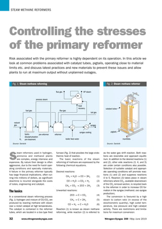
  • 1. Steam methane reformers 33 www.nitrogenandsyngas.com Nitrogen+Syngas 359 | May-June 2019 syngas syngas syngas cooling syngas cooling boiler feed water boiler feed water reformer reformer pre-reformer pre-reformer hydro- desulphurisation pre-treatment hydro- desulphurisation pre-treatment tail gas tail gas natural gas natural gas H2 H2 heat recovery heat recovery process steam process steam flue gas flue gas HP steam HP steam flue gas flue gas fuel gas fuel gas Fig. 1: Steam methane reforming Source: Sandvik catalyst tubes catalyst tubes manifolds manifolds pigtails pigtails Fig. 2: Steam methane reformer Source: Sandvik S team reformers used in hydrogen, ammonia and methanol plants are complex, energy intensive and expensive. By nature their design is often aggressive, due to the need for harsh oper- ating conditions and specialty materials. A failure in the primary reformer typically has large financial implications, often run- ning into millions of dollars, as significant downtime is incurred alongside the costs of tubes, engineering and catalyst. The basics In a conventional steam reforming process (Fig. 1) hydrogen and mixture of CO/CO2 are produced by reacting methane with steam over a nickel catalyst at high temperatures. The catalyst is contained in the reformer tubes, which are located in a box type fired furnace (Fig. 2) that provides the large endo- thermic heat of reaction. The basic reactions of the steam reforming of methane are expressed by the following chemical equations. Desired reactions: CH4 + H2O → CO + 3H2 (1) CO + H2O → CO2 + H2 (2) CH4 + CO2 → 2CO + 2H2 (3) Unwanted reactions: 2CO → C + CO2 (4) CH4 → C + 2H2 (5) CO + H2 → C + H2O (6) Reaction (1) is known as steam methane reforming, while reaction (2) is referred to as the water gas shift reaction. Both reac- tions are reversible and approach equilib- rium. In addition to the desired reactions (1) and (2), other side reactions (3, 4, and 5) are under certain conditions also possible. Selection of suitable catalyst and appropri- ate operating conditions will promote reac- tions (1) and (2) and suppress reactions 4 to 5. Reaction (3) takes place in steam reformers where CO2, available downstream of the CO2 removal section, is recycled back to the reformer in order to increase CO for- mation in the syngas (methanol, oxo syngas production). The conversion is favoured by a high steam to carbon ratio (in excess of the stoichiometric quantity), high outlet tem- perature, low pressure and high catalyst activity. There are restrictions and limita- tions for maximum conversion: Controlling the stresses of the primary reformer Risk associated with the primary reformer is highly dependent on its operation. In this article we look at common problems associated with catalyst tubes, pigtails, operating close to material limits etc. and discuss latest practices and new materials to prevent these issues and allow plants to run at maximum output without unplanned outages.
  • 2. Steam methane reformers Nitrogen+Syngas 359 | May-June 2019 www.nitrogenandsyngas.com 33 Fig. 3: Geometry of reformer furnaces Top-fired furnace Side-fired furnace Terrace wall-fired furnace Bottom-fired furnace Source: IKR Richter l A steam to carbon ratio that is too high will make the process less energy effi- cient, large quantities of excess steam have to be condensed and high volumet- ric steam flow will increase the equip- ment cost. Low steam to carbon ratio will improve the energy efficiency, but can form carbon in the catalyst pores and other undesirable byproducts. l An operating temperature that is too high poses problems of heat transfer and lowers the mechanical strength of the reformer tube material (metal temperatures up to 960°C under pres- sure of about 35 bar). Low operating temperature reduces the conversion, but sometimes this offers an attractive possibility for conversion completion under optimum conditions downstream the primary reformer; l An operating pressure that is too low increases the cost of equipment and makes the reforming process inef- ficient, as it is always necessary to compress the produced syngas at higher pressures for further processing (purification and synthesis). There are mechanical limits for higher reforming pressures, but in general higher reform- ing pressure reduces the overall operat- ing and investment cost. l Catalyst with too high activity could at first improve the conversion rate, but because of its sensitivity, it may easily lose activity due to feedstock impurities, or because of maloperation. Small size catalyst in a given total reformer tube volume will present a higher surface to catalyst volume ratio and thus a higher conversion rate and a better approach to equilibrium, but also gives a higher pres- sure drop. Loss of activity may lead to reformer tube overheating, as reduced conversion means less heat absorption for the endothermic reforming reaction. Primary reformer configurations Several configurations of reforming fur- naces are in use today, characterised mainly by the disposition and position of the burners. The most common types are top-fired, side-fired and terraced wall-fired reformers. Bottom-fired reformers are not very common in modern syngas plants. Fig. 3 shows the overall geometry of these reformer furnaces. The top-fired reformer uses multi- ple rows of reformer tubes with burners located in the arch on each side of the tubes. The heat to the reformer tubes is supplied by the radiating products of combustion. The main advantage of this configuration is the few burners relative to the reformer tubes, the higher radiant effi- ciency, the presence of the high heat flux zone in the “cold” inlet of the feedstock and the very large reformer tube number which can be accommodated in one radi- ant box. The main disadvantages are the limitation in the heat input control and the hot operating level at the top. The side-fired reformer has multiple radiant wall burners along both side walls and one row of reformer tubes in the mid- dle of the box. The heat to the reformer tubes is emitted from the radiant walls. The main advantage is the uniform heat distribution and the very good heat input control. Disadvantages are the large num- ber of burners required, the lower radi- ant efficiency and the size limitation of the fired box (single box for 100 to 150 reformer tubes). The terraced wall type, developed by Foster Wheeler may be regarded as an intermediate between the side-fired and bottom-fired reformers. The reformer has inclined walls with several terraces on which upward firing burners are installed. This unique burner positioning makes it possible to adjust the heat flux in each zone. Bottom-fired furnaces have a rather con- stant heat flux profile along the reformer tube with high metal temperatures on the outlet side. The high heat flux and the high reformer tube skin temperature at the upper part of the reformer is the main characteristic of top fired reformers. In the side-fired and the terraced wall reformer the heat flux along the reformer tube and the conversion are more uniform. In Fig. 4 the respective profiles of reformer tube skin temperature, heat flux, and methane conversion are shown for the two most common reformer furnaces. In a conventional reforming process only 40% of furnace duty is absorbed by the endothermic heat of reaction. About 35% is recovered in the form of waste heat export steam, by utilising part of the
  • 3. Steam methane reformers 33 www.nitrogenandsyngas.com Nitrogen+Syngas 359 | May-June 2019 potential production potential production 10 10 20 20 30 30 40 40 50 50 60 60 70 70 80 80 90 90 100 100 max tubeskin temp max tubeskin temp heat flux heat flux process gas temp process gas temp methane conversion methane conversion process gas pressure process gas pressure in in out out heated tubelength, % heated tubelength, % Top-fired reformer profiles Top-fired reformer profiles 0.14 0.12 0.10 0.08 0.06 0.04 0.02 0.00 0.14 0.12 0.10 0.08 0.06 0.04 0.02 0.00 1.0 0.8 0.6 0.4 0.2 0.0 1.0 0.8 0.6 0.4 0.2 0.0 27 26 25 24 27 26 25 24 1,300 1,200 1,100 1,000 900 800 700 600 500 400 300 200 1,300 1,200 1,100 1,000 900 800 700 600 500 400 300 200 pressure, bar pressure, bar temperature, °C temperature, °C heat flux, 10 3 kJ/m 2 s heat flux, 10 3 kJ/m 2 s CH4 conv. CH4 conv. 10 10 20 20 30 30 40 40 50 50 60 60 70 70 80 80 90 90 100 100 max tubeskin temp max tubeskin temp heat flux heat flux process gas temp process gas temp methane conversion methane conversion process gas pressure process gas pressure in in out out heated tubelength, % heated tubelength, % 0.14 0.12 0.10 0.08 0.06 0.04 0.02 0.00 0.14 0.12 0.10 0.08 0.06 0.04 0.02 0.00 1.0 0.8 0.6 0.4 0.2 0.0 1.0 0.8 0.6 0.4 0.2 0.0 17 16 15 17 16 15 1,300 1,200 1,100 1,000 900 800 700 600 500 400 300 200 1,300 1,200 1,100 1,000 900 800 700 600 500 400 300 200 pressure, bar pressure, bar temperature, °C temperature, °C heat flux, 10 3 kJ/m 2 s heat flux, 10 3 kJ/m 2 s CH4 conv. CH4 conv. Side-fired reformer profiles Side-fired reformer profiles START cracks 30% from inner wall START cracks 30% from inner wall GROWTH cracks grow to break inner bore GROWTH cracks grow to break inner bore FAILURE cracks progress to outer wall FAILURE cracks progress to outer wall Fig. 5: Progression of creep through a reformer tube Source: IKR Richter Source: IKR Richter Fig. 4: Reformer furnace temperature and heat flux profiles latent heat of the syngas for CO2 removal and by preheating feed stock-combustion air or boiler feed water in the convection section of the reformer, where flue gas is cooled from 900 to 950°C to about 125 to 150°C. In the region of 20 to 25% of the heat applied is lost in the stack, in cooling water and in heat losses. Overview of reformer tubes The most critical item in a fired reformer are the reformer tubes in which the catalyst is placed. Reformer tubes constitute up to the 30% of the total reformer cost. For mechanical and process reasons, a typical reformer tube is 10.0 to 14.0 m long, with ID of 75 to 140 mm and wall thickness between 8 and 15 mm. Reformer tubes are usually centrifugally cast and machined in the internal borehole. The tubes are typi- cally made in 3-4 sections consisting of individual castings. The size of the primary reformer has increased step by step over the last dec- ades due to increasing ammonia plant capacities. Whilst a primary reformer for a 400 t/d ammonia plant designed in the 1960s had less than 200 reformer tubes, a reformer for a 3,300 t/d ammonia plant designed nowadays is equipped with more than 400 reformer tubes arranged in eight rows. Although ammonia plant capacities have increased considerably the num- ber of installed reformer tubes, i.e., the installed heat exchange area, has been reduced continuously for a given capac- ity. A modern reformer for an ammonia plant capacity of 1,000 t/d has less than 900 m2 heat exchange area. The same reformer designed more than 30 years ago had a heat exchange area of more than 1,300 m2. Together with the optimi- sation of the reformer tube pitch, i.e., the tube-to-tube distance and the tube row dis- tance, a very compact reformer design is available today. Stress to rupture of reformer tubes The high operating temperature and pres- sure to which the primary reformer tubes are exposed mean that the reformer tubes are close to the metallurgical limits and therefore operate in what is commonly known as the, “creep regime”. This means that reformer tubes will suffer gradual plastic deformation, resulting in micro voids, which develop into large cracks with time in service. Eventually the cracks will propagate throughout the thickness of the reformer tube such that process gas can leak from the reformer tube into the flue gas side of the reformer. This is illustrated in Fig. 5, which highlights the progression of creep through a reformer tube with time. Once cracks have reached the inner wall the reformer tube can be considered to have failed. Although this will normally take many years it can, in very specific pro- cess circumstances, happen in a matter of minutes. As can be seen from Fig. 6, stress to rupture is dependent on the tube wall temperature with modern micro-alloys offering significant benefits over older materials. As a result the tube wall thick- ness has been reduced considerably whilst keeping the same design tube life time as before (100,000 hour).
  • 4. Steam methane reformers Nitrogen+Syngas 359 | May-June 2019 www.nitrogenandsyngas.com 33 Microalloy: 35Ni/25Cr/additions Microalloy: 35Ni/25Cr/additions HP 50 modified: 35Ni/25Cr/Nb HP 50 modified: 35Ni/25Cr/Nb IN 519: 24Cr/24Ni/Nb IN 519: 24Cr/24Ni/Nb HK 40: 25Cr/20Ni/Nb HK 40: 25Cr/20Ni/Nb 800 800 850 850 900 900 950 950 1,000 1,000 temperature, °C temperature, °C 50 40 30 20 10 0 50 40 30 20 10 0 stress rupture, N/mm 2 stress rupture, N/mm 2 Fig. 6: Stress-to-rupture values of reformer tube materials Source: IKR Richter 1960 1960 1974 1974 1978 1978 year year 1995 1995 2005 2005 Low carbon stainless wrought pipes Low carbon stainless wrought pipes HK 40 25/20 Cr/Ni HK 40 25/20 Cr/Ni HP modified 25/35/1 Cr/Ni/Nb HP modified 25/35/1 Cr/Ni/Nb Microalloy 25/35/1 Cr/Ni/Nb plus additions Microalloy 25/35/1 Cr/Ni/Nb plus additions IN 519 24/24 Cr/Ni IN 519 24/24 Cr/Ni creep strength creep strength tubes made by centrifugal castings, high carbon 0.4% tubes made by centrifugal castings, high carbon 0.4% Fig. 7: Development of reformer tube materials Source: IKR Richter Development of reformer tube materials The materials used for reformer tubes in recent decades are illustrated in Fig. 7. The first centrifugally cast reformer tubes were made of HK 40, a material contain- ing 25% chromium and 20% nickel. Today micro­ alloyed steels are used that contains 25% chromium, 35% nickel, niobium and traces of other elements like zirconium and titanium. As alloy strengths have increased, tube wall thicknesses have decreased, thus reducing the thermal stress, and process volumes have increased, whilst keeping the same design tube life time as before. A 14 mm thick reformer tube made of microalloyed steel would have a wall thick- ness of approximately 17 mm if made out of HP modified and more than 30 mm if made out of HK 40. Clearly such thick reformer tubes do not represent an optimal design, and therefore reform- ers utilising older tube metallurgies will have a larger number of narrow diameter tubes. The reformer tube inlet pressure, the inside diameter of the tubes and the peak tube wall temperatures, i.e. the tube design temperature, can be increased without having to utilise reformer tubes with an unacceptably large wall thick- ness. Reformer tube inlet pressures have increased from around 20 barg up to more than 40 barg and the inner diameter of the reformer tubes has increased in steps from 97.2 mm to 127 mm over the last decades. The strength improvement between HK 40 and later alloys is due to the increased amount of secondary carbides, which are finely distributed throughout the parent material. They prevent the movement of dislocations through the material and hence reduce the extent of creep dam- age. In HK 40 only the chromium forms carbides whilst for the later alloys, niobium forms secondary carbides. Titanium, zirconium, tungsten and cae- sium are all strong carbide formers and form finer carbides that last longer, there- fore providing higher strengths that are retained for longer. These higher strengths allow for a reduction in reformer tube wall thickness when utilising modern alloys. By changing to an improved reformer tube material it may permit, for example, a reduction of the overall reformer tube count could be reduced or an increase to the inside reformer tube diameter. The generally accepted methodology for designing reformer tubes is to utilise the Larson-Miller plot with the appropriate data for the metallurgy to be used. This plot can be used to determine whether the assumed reformer tube dimensions and operating conditions will deliver the required reformer tube life time. The reformer tube dimensions or operating conditions can then be varied to achieve the required design life time. Most reformer designers or reformer tube vendors design the reformer tubes to provide 100,000 hours (or circa 11 years) of continuous operation based on the assumed design conditions. However, this steady state approach does not take into account start-ups and shutdowns, designers tend to use 75-85% of the mean stress to rupture values allowing for start- up and shutdown transients. Deviations from these assumed design conditions will clearly affect the achievable reformer tube life time. New alloy materials for reformer outlet systems Outlet systems are an important part of steam methane reformers. Although these elements are typically located outside of the reformer firebox, they operate at severe conditions up to the metallurgical limits and while significant research efforts have been made over the last 30 years in improving alloys used for steam reformer catalyst tubes, no major efforts were devoted to improving outlet system materials. Outlet manifold materials differ depend- ing on reformer designer preferences. Typi- cally, low temperature systems with design temperatures below 829°C use either 800 HT or cast equivalent 20Cr-32Ni, while designs targeted for higher temperatures use cast materials 20Cr-32Ni almost exclusively. 20Cr-32Ni alloy material supplied by the Schmidt+Clemens Group is named Cen- tralloy® G4859. This alloy is a low carbon alloy designed to maintain good ductility after ageing and a good creep resistance in the range of 800°C to 1,000°C. Niobium is used as carbide forming element (20Cr-32Ni-Nb). A substantial benefit of the cast alloy with Nb is that the creep strength is about 50% higher than the wrought alloy (800 HT) with Al and Ti. New Schmidt+Clemens materials have recently become available for out- let header components as alternatives to standard material GX10NiCrNb32-20
  • 5. Steam methane reformers 33 www.nitrogenandsyngas.com Nitrogen+Syngas 359 | May-June 2019 Composition, wt-% C Si Mn Cr Ni Nb Ti/Zr Fe Centralloy® G4859 0.1 1 1.5 20 32 1 - balance Centralloy® G4859 Micro 0.1 1 1.5 20 32 1 additions balance Centralloy® H101 Micro 0.13 0.5 0.5 25 37 0.5 additions balance Source: Schmidt+Clemens Table 1: Typical composition of Schmidt+Clemens low carbon alloy materials for outlet components 0 10 20 30 40 50 60 20 220 420 620 820 1,020 temperature, °C G4859 G4859 Micro H101 Micro elongation l=5d, % 1 10 100 650 750 850 950 1,050 temperature, °C minimum G4859 minimum G4859 Micro minimum H 101 Micro initial stress, M/a 0 50 100 150 200 250 20 220 420 620 820 1,020 temperature, °C G4859 G4859 Micro H101 Micro 0.2% yield strength, M/a Fig. 9: Elongation to rupture comparison Fig. 10: Minimum creep resistance comparison Fig. 8: 0.2% yield strength comparison Source: Schmidt+Clemens Source: Schmidt+Clemens Source: Schmidt+Clemens or ASTM CT 15C (20Cr-32Ni-Nb). These materials named as Centralloy® G4859 Micro and Centralloy® H101 Micro can significantly improve creep resistance and ductility after ageing over the standard alloy 20Cr-32Ni-Nb. The main advantage for plant opera- tors are wall thickness reduction of out- let header components, with benefits in weight reduction, and increased resistance to thermal shock. Alternatively, maintain- ing original wall thickness, lifetime of such components can be substantially increased keeping the same design and operating conditions. The nominal composition of these mate- rials is represented in Table 1. Centralloy® G4859 Micro A logical improvement of 20Cr-32Ni-Nb is the development of a micro alloy version – Centralloy® G4859 Micro. Addition of small quantities of elements like titanium and composition optimisation has enhanced significantly material performance. Like standard material G4859, this alloy has a maximum operating temperature of 1,000°C. Centralloy® G4859 Micro has been available in the market since 2011. Currently more than 102 outlet manifold arms and 2950 outlet reducers have been installed in service, together with more than 40 T-pieces and transition cones. Performance of these components in operation has been regarded as excellent. Centralloy® H 101 Micro Low carbon versions of HP-Nb (25Cr-35Ni- Nb) were originally designed for operation under severe corrosion conditions only requiring a moderate ductility. These condi- tions are typical in steam cracker applica- tions. Nevertheless, these materials were described in the literature as a potential replacement of 20Cr-32Ni-Nb materials, especially in designs requiring higher oper- ational temperatures. Unfortunately, lower ductility after aging performance compared with 20Cr-32Ni-Nb has been regarded as the main drawback. Therefore, material replacement in outlet manifold components was not advisable. Schmidt+Clemens has designed a micro alloyed version of this low carbon material, with an optimised chemical composition, capable of enhancing creep resistance and ductility after ageing over existing 20Cr-32Ni-Nb materials. Further- more, higher chromium and nickel con- tents would allow outlet components to be designed for higher temperatures up to 1,050°C. The first reference in reformer outlet components was supplied in 2016. Characterisation and results During the development of these new materials, Schmidt+Clemens carried out extensive characterisation of tensile prop- erties and creep performance. Additionally, significant efforts were made on material microstructural characterisation and accel- erated ageing tests in order to study the driving forces regarding material ductility exhaustion. Tensile tests Room temperature (RT) and high tempera- ture tensile tests were performed on these three materials. 0.2% yield strength, ulti- mate tensile strength and elongation to rupture properties were measured. Results for 0.2% yield strength (Fig. 8) showed that the addition of micro alloy- ing elements has improved material yield strength in comparison with alloy G4859. When comparing the ultimate tensile strength (UTS) for these materials, no rel- evant differences could be seen between G4859 and G4859 Micro, while H101 Micro UTS values seem to be slightly inferior. Elongation to rupture values results (Fig. 9) indicated a superior ductility of G4859 at low temperatures, while H101 Micro has a better ductility at higher tem- peratures. G4859 Micro alloy has a slightly lower ductility. The relevant reduction on ductility seen for alloy G4859 in the range of 700-900°C might be related to the sta- bility of brittle intermetallic phases like G-phase, leading to a localised embrittle- ment of the alloy material. Creep tests Creep resistance is one of the major require- ments for these type of materials. Creep strengthening is accomplished by the forma- tion of carbides in the microstructure. Mate- rial creep resistance is typically shown in Larson-Miller curves (parametric stress rup- ture strength). Minimum parametric stress to rupture values for a life time of 100,000 hr is represented in Fig. 10.
  • 6. Steam methane reformers Nitrogen+Syngas 359 | May-June 2019 www.nitrogenandsyngas.com 33 0 10 20 30 40 50 0.0 7.5 7.8 8.3 8.6 9.0 9.4 9.4 0 500 1,000 500 1,000 500 1,000 500 RT 750 750 850 850 950 950 1,000 Centralloy G4859 Centralloy G4859 Micro Centralloy H 101 Micro P=T(K)*(4.67 + log t)/100 elongation, % Fig. 11: Ductility after aging comparison catalyst tube catalyst tube pigtail pigtail main transfer line main transfer line Fig. 12: Pigtails overview Source: Sandvik Source: Schmidt+Clemens Both microalloyed materials have a superior creep resistance compared with G4859. Small additions of strongly carbide forming elements lead to the formation of stronger and more evenly distributed sec- ondary carbides in the austenitic matrix. Ductility after aging Ductility after aging is a major requirement for these types of materials. Material samples are aged in a furnace (controlled temperature and time of ageing), and later aged samples are tensile tested at room temperature to measure elongation to rup- ture. Ageing conditions and test results are shown in Fig. 11. Considering all three materials, supe- rior ductility after ageing performance is achieved with alloys H101 Micro and G4859 Micro in comparison with alloy G4859. Such superior behaviour might be explained by the formation of more ther- modynamically stable primary carbides and due to delay/suppression of intermetallic phase formation. FE modelling of outlet manifolds Finite element analysis (FEA) provides the opportunity to test real components simulating the continuous operation in the furnace. FEA can be carried out on outlet header systems, but the model accuracy strongly depends on the quality of the creep model, boundary conditions, geo- metrical models and correct meshing. Creep modelling is clearly the most complicated issue. Manufacturers like Schmidt+Clemens provide stress to rup- ture values parametrised in models like Larson-Miller. Such stress to rupture data is not adequate for dynamic modelling where creep elongation and stress relax- ation behaviour information is required. Therefore, having a good creep behaviour modelling is imperative in providing good FEA results. Analysis results indicate that new materi- als are improving time to rupture compared with standard 20Cr-32Ni-Nb materials. Nev- ertheless, inadequate operation or main- tenance of outlet header components can lead to overstressed zones that can lead to early component ruptures in operation, even if the entire header is securely designed according corresponding standards. Simulation study results Two simulation steps were considered for all three materials. The first step consid- ered a static structural simulation of just one second, to evaluate stress/strain dis- tribution on the outlet header. The second step considered a one-year simulation of the part under creep regime. Wall thick- ness of the component was estimated using ASME B31.3 calculations for alloy material G4859 considering a design time of 100,000 hours. Some surprising results were obtained from the static structural simulation. Even considering that reformer tube counterweight system was compensat- ing all weight stresses over the material, significant part deflection was observed on header tube arms due to the thermal expansion of the transfer line. All material results showed that the outlet header tube support location has a strong impact on the stress distribu- tion in the component. Supported areas and T-piece/arm tube zones had the high- est stresses in these models. Therefore, these parts are the most susceptible to failure due to creep damage. Life time predictions can be applied into the model considering the Larson- Miller curves for each material. Most stressed portions of the outlet header are determining the lifetime of the component in operation. According to the simulation, mate- rial G4859 will have a time to rupture of 133,000 hours in such an area. On the other hand, more creep resistant material like G4859 Micro (255,000 hours) and H101 Micro (220,000 hours) will have a sig- nificantly higher time to rupture in operation. Lack of maintenance or inadequate alignment of header components (like arm supports) might add additional stresses on the part and, consequently, reduce dra- matically the lifetime of the outer header. Results of these simulation efforts show that material selection is the most critical part in ensuring that the outlet sys- tem is able to achieve the required design time. In addition, components of the entire header system like tube supports, can also have a significant impact in the out- let header performance/ life if they are not working adequately. Pigtail material selection Pigtails are piping systems for the connec- tion of the catalyst tubes to the manifolds in both the inlet and outlet of the reformer are prone to different mechanical and ther- mal stresses and possible failures (Fig. 12). Inlet pigtails are less critical as they work at lower temperatures (550-600°C), but still require careful material selection. Out- let pigtails, on the other hand, which carry the reformed gas from the catalyst tubes to the collection manifold, must be able to
  • 7. Steam methane reformers 44 www.nitrogenandsyngas.com Nitrogen+Syngas 359 | May-June 2019 T 500°C → diffusion of the gases Oxygen: O2 Carbon: C, CO, CO2 Nitrogen: N, N2, NH4 Sulphur: S, SO2 Molten salts: Na, K,V tube surface protective oxide layer Cr2O3 oxides (oxidation) Cr23C6 carbides (carburisation) CrN2 nitrides (nitriding) Ni2S sulphides (sulphidation) slag Fig. 13: High temperature corrosion Source: Sandvik withstand much higher temperatures (800- 950°C) and are subject to harsher high tem- perature corrosion mechanisms that require higher alloyed grades. Materials such as 20Cr32Ni grades or UNS N08810 or UNS N08811 are typically selected due to their high creep strength. Since most of the major components of the primary reformer have advanced over the years, pigtails are usually per- ceived as the weakest point, often requir- ing replacement much earlier than the reformer tubes or manifolds. In addition to resisting the thermal expansion from the process system, pigtails must be able to withstand creep fatigue and stress relax- ation cracking. Hence, the overall objective when selecting materials for pigtails is to provide more reliable pigtails with a longer lifetime that allow the replacement of all major parts at one time with no intermedi- ate shutdown period. In pigtails, due to the nature of the application, which brings some mechani- cal fatigue to the tubes and the bended shape they have, creep resistance is the most important property. To prevent the material from cracking due to low creep strength rupture, and consequently burst into the crack itself, it is important to have a resistant material. Ruptures can lead to hydrogen leaks with risk of explosion and risk to the safety of personnel. The properties of stainless steels are different when there is “diffusion” of gases into the protective oxide layer (Fig. 13). In these corrosive environments good resistance to creep and structure stability is required. The grain size of pigtails also has a huge influence on the mechanical behaviour of these materials. Industry requirement for these par- ticular materials regarding grain size is commonly found in standards and speci- fications as “average grain size 5 or coarser” according to ASTM E112. This specification does not, however restrict the grain size distribution. It is known that the upper and lower tail of the statistical distri- bution has a large influence on mechanical behaviour of materials. There is therefore a general need for precise grain size characterisation and grain size control, which has a strong influ- ence on creep strength. Restricted grain size is also required in the bent portion of U-bends. Cold bending followed by anneal- ing may cause the grain size to fall outside the preferred grain size window. Research into grain size and grain size control is ongoing at Sandvik, who can provide narrow grain size windows upon request. A commonly used pigtail material is Sandvik Sanicro 31HT, an austenitic nickel- iron-chromium alloy characterised by: l high creep strength; l very good resistance to oxidation; l good resistance to combustion gases; l very good resistance to carburisation; l good resistance to nitrogen absorption; l good structural stability at high temper- atures; l good weldability. Sandvik Sanicro™ 31HT can be used at temperatures up to about 1,100°C. In order to have the best ductility, it should be used above 700°C. Referring to industry standards and the most common specifications, an average grain size of 5 or coarser is required which can be mainly derived from ASTM B 407. The methodology is described in ASTM E 112, however, this specification does not contain any requirement regarding the grain size distribution. Consequently, the manufacturing process of pigtails must be adjusted in a manner that the properties and hence the behaviour of these tubes lead to an increasing service lifetime. The manufacturing process is of even greater importance when it comes to the bending of pigtails. Based on the fact that there are many different furnace designs, pigtails come in different shapes, they may be straight but may also have bends. A high amount of strain is induced dur- ing the bending process and it is impor- tant to have appropriate control of the deformation, minimise ovality and avoid scars or superficial defects. Depending on the degree of cold work induced dur- ing the bending process, this will cause the material to change its microstructure which will then have an impact on the per- formance during service lifetime. In order to improve pigtail performance it is rec- ommended to perform a final annealing heat treatment. Reformer revamping Many critical components of the steam reformer unit, such as the catalyst tubes, pigtails, intermediate tube sheets and shield coils are inevitably forced to operate very close to their material design limits and there is a time frame, before a point of failure, when symptoms or warning signs can be identified in time and with good reliability, avoiding unplanned outages and potential risk to plant personnel. In many cases, conditions that were already critical can be exacerbated when improvement modifications or revamping activities are carried out, particularly when the plant owner does not request a licen- sor assessment, which is fundamental to minimise risks and avoid any subsequent surprises on plant consumption figures. The following two cases demonstrate the importance of carrying out a detailed data analysis of the whole reformer to identify where abnormal conditions or upset operating parameters are located. Revamp case 1 In this first case, Casale was awarded an EP project for an ammonia plant revamp to reduce energy consumption and increase plant ammonia production capacity from 1,700 to 1,900 t/d.
  • 8. Steam methane reformers Nitrogen+Syngas 359 | May-June 2019 www.nitrogenandsyngas.com 44 hot steam superheating coil cold steam superheating coil process air coil feed preheating coil BFW preheating coil fuel gas coil mixed feed coil flue gas from radiant chamber SSH burners flue gas to ID fan hot steam superheating coil cold steam superheating coil process air coil removed surface feed preheating coil BFW preheating coil cold process air coil fuel gas coil mixed feed coil flue gas from radiant chamber SSH burners flue gas to ID fan Fig. 14: Original arrangement of primary reformer convection section Fig. 15: Revamped arrangement of primary reformer convection section A detailed assessment of the plant revealed many limitations in the primary reformer convection section (Fig. 14) as it had already been revamped many times. The reformer is an induced draft top fired type with an omega convection section con- figuration and an external auxiliary boiler. In the past, the client decided to replace the mixed feed coil and process air coils with new ones with the aim to reduce the fuel consumption to the reformer arch and tunnel burners which was progressively increasing. It was decided to proceed pro- viding an increased surface on both coils of about 50%. Following this modification, the temper- ature of the flue gas stream coming from the reformer hot leg dropped so much that the steam superheating burners had to be operated at their maximum heat release in order to reach the desired steam super- heated temperature. However, this prac- tice can create issues with the steam superheater coil. Analysis After data collection, an overall detailed analysis of the primary reformer was per- formed, and the original reformer design was verified. It was found that both the mixed feed coils and the process air coil, before replacement, were significantly underper- forming and were unable to achieve the desired process stream outlet temperature despite the flue gas temperature from the tunnel section being higher than required. Based on Casale’s experience, this primary reformer section is very critical and subject to mechanical degradation, accelerated by operating conditions, which normally lead to minor or major underper- formance of the coils. This phenomenon is made worse by the practice to compensate for the temperature drop by increasing the tunnel combustion heat release. The second point to be analysed was related to the new geometry of the coils which, it turned out, affected performance of the cold steam super heating coil. This solution in effect moved a problem from one section to another: the cold steam super heating coil section. The coil was found be operating well below the required performance and below the expected performance considering operation aging. This was demonstrated by the hard firing of the steam superheat- ing burners. Solution The plant was revamped with the aim to pre- serve the existing mixed feed and process air coil geometries considering the project targets and at the same time solving the bal- ance issues of the convection section. The overall steam consumption required for the reforming reaction and internal plant use was decreased and optimised. In this way, it was possible to reduce the required duty of the BFW preheater coil, whose surface was partly replaced by a new coil, with the purpose to “cold” preheat the process air so that the surface of the existing “hot” process air coil could be reduced (Fig. 15). These modifications allowed more heat to be released in the hot leg available downstream for steam, while reducing the steam flow making the coil surface ade- quate despite the plant capacity increase. In the end, the original normal oper- ability of the steam superheating burner section was restored and the whole con- vection section was rebalanced. As a con- sequence of reducing the heat release from the superheating burners, the oper- ating conditions of the superheater coil is milder, and stress is reduced. Since it was also found that the cold steam superheating coil together with intermediate tube sheets had lost most of their residual life, a new design was provided that fitted the geometry of the existing one but with upgraded materials of construction. Revamp case 2 In this second case, Casale was requested to assess the operation of a steam reformer unit for a 1,500 t/d methanol plant. The steam reformer had been revamped many Source: Casale Source: Casale
  • 9. Steam methane reformers 44 www.nitrogenandsyngas.com Nitrogen+Syngas 359 | May-June 2019 a) b) c) (A1 – A2): combustion air sub-header balancing damper (B – outlet): burner damper to radiant chamber inlet -5 mm H2 O outlet A1 A2 B 80.5 86.0 49.0 80.1 88.7 86.5 Fig. 16: Pressure distribution on the combustion air ducts Fig. 17: Combustion system a) before modification; b) after orifice plate installation; c) pressure drop before (blue) and after modification (orange). Calibrated orifice plate located in position B. Source: Casale times in the past, mainly in the convec- tion section, without any modifications to the radiant chamber. Some years later the catalyst tubes at the end of their life were replaced by new ones manufactured with the latest generation microalloy material. During the same turnaround, it was decided to change all primary reformer original low- NOx burners with the new generation ultra- low NOx burners. The reformer is a very big (16 tube rows) balanced draft top-fired type with a horizontal convection section. Analysis After data collection, an overall detailed analy­ sis of the primary reformer was performed and the original reformer design verified. The plant process scheme is based on pure steam reforming technology, which makes the furnace operating conditions very critical since it is requires a reforming process outlet temperature of about 900°C. From a preliminary analysis of the recorded tube skin temperatures, a tem- perature deviation was found ranging from 30°C for the inner tube rows to 50 °C for the outer tube rows. Due to the use of ultra-low NOx burn- ers it was necessary to analyse the flue gas distribution inside the radiant cham- ber in greater detail, since this technology limits pollutant emissions by forcing the burner to operate with inefficient combus- tion, staging the fuel into many zones (two or more). As a result, the flame shape is worsened in term of dimensions, affecting both the radiant chamber efficiency and the catalyst tube skin temperature profile. From the computational fluid dynam- ics analysis, it was clear that the tunnel extraction system was not adequate to mitigate the poor distribution in the radiant chamber, while the combustion air distribu- tion was adversely affected by the ultra-low NOx burners which require a much lower pressure drop on the air side than conven- tional low NOx burners. Fig. 16 shows the pressure distribution on the combustion air ducts. During the site survey, it was found that the entire system was balanced by regulat- ing the firing of each burner throttling the relevant combustion air damper and fuel gas valve. Of course, this practice relied exclu- sively on the plant operators and is com- monly applied to steam reformer units to mitigate radiant chamber maldistribution and provide a uniform catalyst tube skin operating temperature. However, although this approach is acceptable to reduce stresses of the catalyst tubes, it can lead to burners being operated with process parameters far from the operability and stability range. From a mechanical point of view, the outlet pigtails proved to be the most criti- cal components of the system. Despite the catalyst tubes operating at very high temperatures, the new micro-alloy mate- rial together with the low design pressure of the tubes, provided sufficient safety margin on the tube thickness which can be converted to an extended tube life. The outlet pigtails, on the other hand, were manufactured of Alloy 800 HT and were operating very close to the material design limit. In this case, the reformer outlet tem- perature variation had to be strictly con- tained within a reasonable range. Solution Some rectifications were proposed in order to solve the issues on the combustion sys- tem with the aim to preserve and extend the life of critical items. On the air side, a dedicated calibrated orifice plate was designed and provided just before the burner damper to ensure the required pressure drop for distribution and the necessary air split ratio between the inner and outer burners. It should be noted that the modification itself does not have an impact on the overall duct pressure drop since the local damper Source: Casale
  • 10. Steam methane reformers Nitrogen+Syngas 359 | May-June 2019 www.nitrogenandsyngas.com 44 Fig. 18: Crack in reformer tube Source: REFORMER SERVICES head loss is moved to the calibrated orifice plate without affecting the combustion air fan operation (Fig. 17). On the flue gas side, it was clear that, the uneven distribution was attributable to the geometry transitioning from the huge radiant chamber to the small cross- sectional area of the convection section, which led to some preferential pathways in the middle of the reformer. A new hole distribution pattern was provided for the tunnel walls to balance the flue gas extrac- tion system and tighten the flow deviation. The effect of these measure were: l to reduce the temperature spread recorded on the skin temperatures and on the outlet pigtails by about 40%; l to operate the burners within a safe and operable range; l to have a straightening effect on the flames to reduce the risk of tube impinge- ment. Reformer tube failure mechanisms There are two key operating conditions that must be considered in reformer tube design, the reformer tube operating temperature and the tube-side operating pressure. Large temperature excursions reduce the residual reformer tube life time because higher temperatures increase the rate of loss of secondary carbides which reduce the strength of the parent reformer tube material. As a rule of thumb, a 20°C rise in tube wall temperature will halve the expected reformer tube life time. For example, an excursion of 200°C for six hours will reduce the expected reformer tube life time by approximately nine months. Operation at higher pressure than the design pressure, for example due to higher than expected pressure drop downstream of the primary reformer, will increase the differential pressure across the reformer tubes and therefore reduce the reformer tube life time. Transients such as start-ups and shutdowns will lead to the generation of thermal stresses within the reformer tubes. These stresses are cumulative and so will reduce the ulti- mate reformer tube life time. The faster the increase or decrease in reformer tube temperatures, the greater the stresses and therefore the greater the reduction in the ultimate reformer tube life time. A rapid shut-down can reduce the life time of the reformer tubes by four to six months in comparison to a controlled shutdown. The most common failure mechanism of reformer tube is nearly always due to the creep of the reformer tube material; how- ever, others do exist. A typical creep failure is longitudinal with the crack extending axially from the original failure point in both directions as illustrated in Fig. 18. There are a number of different causes of reformer tube failure depending on the location of the section of reformer tube and the problems that can affect the reformer tubes in these different locations. The root cause of reformer tube failure can be broken into two discrete groups based on whether the section of reformer tube has been overheated due to a general or a local effect, i.e. generalised overheating or localised overheating. Generalised overheating is defined as a large area of the reformer tube being overheated (typically greater than 2 m of reformer tube which affects many tubes). Generalised overheating can be caused in a number of ways, for instance: l The normal overheating process that occurs within a primary reformer due to the operating temperature required by the steam reforming process; l Overheating during transients such as start-ups and shut-downs where the fuel rate has not been sufficiently reduced; l Low catalyst activity due to poisoning or carbon formation, reducing the rate of hydrocarbon reforming and hence the rate of heat absorption; l Fouling of foreign material at the outer and inner surface of the reformer tubes Localised overheating is defined as a small area (typically 1-2 m in length and can be isolated to 5-10 reformer tubes) of the reformer tube being overheated. Again, there are a number of different ways that this can occur due to: l Flame impingement due to poor align- ment of the burners or where the burn- ers ports are blocked; l Catalyst bridging which leads to void formation and hence a reduction in the rate of reforming with the associated increase in tube wall temperature; l Point problems such as the tunnel port effect; l Failure at welds or within the parent reformer tube material due to poor man- ufacturing techniques. With advances in the metallurgy of weld materials this effect has made this less common; however, there are still a large number of reformers that still utilise older weld materials and are vulnerable; l Fouling of foreign material at the outer and inner surface of the reformer tubes. Pinched tubes Isolated hot spots and tube ruptures can occasionally develop on radiant tubes dur- ing operation. Rather than shutting down the furnace to replace these isolated tubes, the tubes are externally pinched by hot crimping both inlet and outlet pigtail tube ends of the damaged reformer tubes when in service. Despite good crimping procedure, there is still a possibility of some leaks at the crimped locations. A second crimping before the pigtail gets cold at 90° to the first crimping can be done if there is space in the straight leg of both inlet and outlet pigtails. Some users use a second crimping as a backup against failure of first crimped locations. If a leak persists there is no alternative but to shut down the reformer furnace for repair or replacement. Thermal shock Thermal shock is very damaging to tube life, it can even cause catastrophic effects to the whole reformer. After a thermal shock event it is important to perform an inspection, check for damage and have a good plan in place to deal with all inspec- tion findings. Ideally the inspection results
  • 11. Steam methane reformers 44 www.nitrogenandsyngas.com Nitrogen+Syngas 359 | May-June 2019 can be compared to a previous inspection. Any damage that occurred during the excur- sion should be evaluated carefully, due to the rapid damage all indications are of importance. After a thermal shock it is much more difficult to predict how the dam- aged areas will react when they are brought back online. Overfiring protection case study In early 2015, when Profertil was per- forming a hot restart of their ammonia plant, an uncontrolled and rapid increase in flue gas temperature was noticed in the primary reformer. After natural gas feed was introduced to the primary reformer, it was observed that a rupture of several catalyst tubes had occurred and the plant was tripped immediately. Profertil requested Haldor Topsoe A/S to take the lead technical advisor role in a thorough root cause analysis, performed to identify the reason(s) for the tube rup- ture incident. The results of this thorough root cause investigation led to a solution that assures such incidents will not happen again. The incident with ruptured tubes not only impaired plant capacity utilisation until the re-tubing of the furnace, but more impor- tantly, the leaked gas from the ruptured tube could have resulted in unsafe condi- tions. Therefore, the possibility of avoiding this type of incident is of paramount sig- nificance to all plants operating with any type of tubular reformers. Following this incident, an automated overfiring protec- tion (OFP) management system that pro- vides four elements of protection against overfiring of primary reformer tubes was developed. The OFP management system addresses both ‘local’ and ‘global’ causes of primary reformer catalyst tube overheating. OFP does not allow fuel header press­ ure increase during start-up and enforces a symmetric burner ignition pattern. Dur- ing start-up, these two protection elements not only help to avoid catalyst tube over- heating but also ensures better heat distri- bution inside the furnace. Moreover, double protection elements of duty and bridge wall temperature limi- tation ensure parity in duty input and duty uptake by adjusting fuel flow to the burn- ers based on maximum estimated duty for the primary reformer at a particular capacity. OFP is suitable and highly relevant for all types of tubular reformer designs. Monitoring tube wall temperature Reformer tubes are highly valuable assets. A large reformer contains hun- dreds of tubes, at an average tube cost of approximately $15k to $30k each, and unplanned outages can result in signifi- cant costs of $350k to $1m a day, so increasing tube life and reducing tube failures is essential asset management. That means having an effective method of temperature measurement. The monitoring of tube wall tempera- tures (TWT) can help optimise catalyst tube life and ensure longevity, energy efficiency and productivity. With better temperature control, operators can increase profit by increasing output and lowering operating cost, resulting in better utilised feedstock, catalyst and fuel. A 2% improvement in output has the potential to save approxi- mately $1 million a year. Issues with the burner, flue gas dis- tribution and the catalyst can all directly affect TWT and lead to premature tube failure. To prevent this, most operators tend to be overly cautious with TWTs. However, excessively cautious firing reduces the reaction rate and thus leads to lower production and/or higher energy consumption – a 10 °C drop in tempera- ture can result in 1% decrease in produc- tivity. Even taking a cautious approach, tube failures can still occur due to hot spots on tubes and hot areas within the convection box. Mechanical stress on the hot tubes increases exponentially, in worst cases causing tube ruptures. Even though producers may be run- ning at a reduced rate, they are still not guaranteed to have a balanced, reliable reformer. Reformer tube failure and pro- cess flow problems come about when tem- peratures are too high. Even operating at temperatures only 20°C above the design temperature can cut a tube’s lifetime in half. Maintaining optimum temperatures is therefore critical. A thermal gradient through the tube wall is more significant at the bottom or close to the bottom of the tube, causing differen- tial creep strain, which is a primary cause of damage. A fifth of all incidents involve tube cracking. Operators are required to have an in-depth understanding of reformer behavior and must also be able to analyse data and make rapid decisions when faced with catastrophic failure. The burners, which fire directly inside the fire box from the top, sides or both, are also very important to tube efficiency, as the flames must not impinge on the tubes or wall. Proper alignment of the burner is very important to avoid flame impinge- ment, gas flow restriction, burner issues, external tube scaling and afterburning (tube leaks). Significant operator experience is nec- essary to fully understand basic reformer construction, process flow, heat transfer principles, background radiation, and emis- sivity along with the cooling effects that occur when the peep door is opened. Reg- ularly opening a peep door can increase stress on the tubes and potentially cool those directly in front of the door by a vari- ance of 30°C. With that in mind, operators need data on the TWT that is accurate, repeatable and reliable. By continually monitoring readings, the operator will get an early warning of increasing tube wall temperatures, which can then be used to counteract potential catastrophic failure. Continuous monitor- ing, likewise, will allow the operator to safely and confidently increase tempera- tures, with a view to increasing production. TWT measurement methods In order to meet the demands for greater production, efficiency and safety, continu- ous 24/7 monitoring is required. Several different temperature measurement meth- ods are available, two examples are given below: l Handheld spot pyrometers enable users to take routine spot measure- ments to optimise steam reformers by maintaining operation closer to design temperatures and, in many situations, the pyrometers can provide adequate accuracy. However, with pyrometers, the operators are only able to view a local spot on the tubes and may miss hot spots in other locations. l Fixed thermal imaging provides more accurate and repeatable results than handheld pyrometers as they are less liable to human error and enable opti- misation of the TWT to ensure a long tube life. Thermal imaging cameras are inserted into the reformer, with the end of the imager ¼ from the inside reformer wall refractory. Imag- ers are water- and air-cooled to ensure accuracy in the hot atmosphere of the reformer. This method improves effi- ciency and minimises the risk of cata- strophic failure.
  • 12. Steam methane reformers 44 www.nitrogenandsyngas.com Nitrogen+Syngas 359 | May-June 2019 Fig. 19: Thermal view inside and reformer tube furnace with data points Fig. 20: Thermal view inside and reformer tube furnace with data points AMETEK Land’s Near Infrared Borescope (NIR-B) 3XR Accurate temperature measurement must take emissivity into account. Within the reformer environment, several objects can reflect off the surface. Handheld pyrometers and visual inspection can wrongly interpret the reflections as real data, causing errors in temperature measurement. Thermal imaging cameras that are mounted strategi- cally within the reformer do not allow this to happen, such as AMETEK Land’s Near Infrared Borescope (NIR-B) 3XR – which is certified for hazardous areas. The fixed thermal imager delivers a high-resolution image, with accurate real-time measure- ments of both the tube skin and refractory surface (Figs 19 and 20). The image, combined with the 90° angle field of view, allows for multiple par- allel tubes to be measured simultaneously. This can dramatically enhance efficiency and safety, as well as provide better asset management and furnace optimisation. One of the major benefits of using fixed thermal imagers like the NIR-B 3XR is their rapid response time. Using the AMETEK Land Image Processing Software (LIPS) provided with NIR-B 3XR, for exam- ple, the software will sound an alarm the moment the tube wall reaches the maxi- mum temperature in any region, identify- ing the problem region and allowing the operator to take corrective measures to fix the issue. Case study Air Liquide, the world leader in gases, technologies and services for industry and health, understands the critical importance of managing TWT and required a solution to deliver highly accurate and more com- plete measurement of the equipment and process, compared to spot temperature measurements, whilst operating in a haz- ardous environment. AMETEK Land recommended its Near Infrared Borescope (NIR-B) 3XR, which pro- vides a high-resolution thermal image with real-time high accuracy temperature mea- surements of both the tube wall and refrac- tory wall surface, allowing for background compensation. With the AMETEK Land solution in place, Air Liquide is now continuously measuring the temperature of reformer tube walls. Gonzalo Navarro, Production Manager at Air Liquide Ibérica de Gases, explains: “Our main drivers in investing in AMETEK Land’s NIR-B 3XR were to extend tube and catalyst life, which we are achieving as a result. We are continuously learning about our reformer, which enables us to balance it correctly and follow online our main and critical asset.” He adds: “Now, our teams can monitor the temperature of the tubes continuously, they are able to make more informed and confident decisions implying greater plant reliability”. Air Liquide’s Research and Development team has since approved the NIR-B 3XR thermal imager for potential installation in additional steam methane reformers. Clariant TWT monitoring Clariant offers various technologies for monitoring the tube wall temperature. The simplest of these, the pyrometer, allows reliable single-point readings of the tube wall temperature by measuring through peepholes. As it is designed for ease of use, pyrometer measurements are limited to tubes which can be accessed through the peepholes. In addition, readings should be corrected for background radiation. Source: Ametek Land Source: Ametek Land
  • 13. Steam methane reformers Nitrogen+Syngas 359 | May-June 2019 www.nitrogenandsyngas.com 44 Fig. 21: Tube scan 360-OD Fig. 22: Tube scan 360-ID A more advanced solution is Clariant’s Thermal Scan, a high-resolution ther- mal imaging borescope which measures temperatures from 600 to 1,100°C at a short, accuracy-enhancing wavelength. The instrument presents a real-time, three- dimensional heat profile of all tube rows in the furnace, allowing easy detection of uneven heat distribution or hot spots. Plant operators benefit from a comprehen- sive temperature survey, which includes thermal images as well as recommenda- tions for burner adjustments. Alternatively, the Thermal Scan Plus Gold Cup has been developed for mea- surements using a golden reflector. This method provides superior precision due to its near-perfect reflectance. The data is used to calibrate the standard Thermal Scan, thus providing an extremely accurate temperature profile of the entire furnace (dT +/- 5°C). These instruments enable more effective troubleshooting, and help operators achieve maximum reformer per- formance and lifespan, without unneces- sary and costly outages. 360° tube inspection With today’s economy plants are pushing their reformers harder than ever to keep up with production needs, this can lead to many issues such as flame impingement, flue gas distribution, catalyst damage and pinching tubes online. All of these can lead to overheating of the reformer tubes around the complete circumference and in the past, the focus has always been on inspecting just the fired side of tubes. These issues are also affecting the non- fired sides of tubes and the industry has seen failures from overheating of these areas in the past. A new method from Reformer Services is now available for detecting damage mechanisms affecting the complete 360° circumference of the reformer tube wall, as well as the full volume of the tube wall thickness simultaneously. The focus is the detection of damage mechanisms in the tube and the ability to size the dam- age on the equipment being inspected. The state-of-the-art technology proprietary crack detection system provides a full body examination of tubes and is able to detect the earliest stages of creep and bulging to the most severe stage of creep to prevent catastrophic failure. This inspection tech- nology is fast and very repeatable using multiple lasers. On-site reporting software is integrated from the computer-controlled data acquisition system. The new inspection technology con- sists of two reformer tube scanner types. The outer diameter reformer tube scanner, Tube Scan-360-OD, (Fig. 21) volumetri- cally inspects 360° circumferentially as it advances along the length of the tube producing real time data with two different technologies while identifying the damaged areas. Only 50 mm clearance is required between tubes. It provides 100% OD cover- age of each reformer tube and 360° crack detection. The internal diameter reformer tube scanner, Tube Scan-360-ID, (Fig. 22) also uses two different inspection meth- ods running concurrently to provide a full 360° examination of the tubes. It provides 100% laser ID coverage and 100% crack detection coverage of each reformer tube. Both reformer tube scanner types are equipped with a powerful proprietary eddy current technique for sensitive crack detection in reformer tubes up to 23 mm wall thickness. Measurements for both strain and crack detection are carried out simultaneously. Cracks can be detected in both the longitudinal and circumferential direction. Both scanner types offer repeat- able accurate and fast inspection results, based on the collection of millions of data points during each tube inspection. All recorded data is used for remaining life assessment. Fouling of reformer tubes Fouling has been described as the major unresolved problem in heat transfer. Foul- ing is generally defined as the accumula- tion and formation of unwanted materials on the surfaces of processing equipment, which can seriously deteriorate the capac- ity of the surface to transfer heat under the temperature difference conditions for which it was designed. In the production of the syngas, fuel combustion in the primary reformer can lead to dust deposits on the outer surface of the reformer tubes and prevent proper heat transfer which diminishes the overall performance of the primary reformer which is the main energy consumer in syngas production. Major detrimental effects of fouling at the reformer tubes in any primary reformer include loss of heat transfer as indicated by charge outlet temperature decrease and the lower value of emissivity which conse- quently increase the energy consumption. Where the heat flux is high, as in primary reformers, fouling can lead to local hot spots resulting ultimately in mechanical failure of the heat transfer surface. Such effects lead in most cases to production losses, higher energy consumption and increased maintenance costs. Loss of heat transfer and subsequent charge out- let temperature decrease is a result of the low thermal conductivity of the fouling layer or layers which is generally lower than the thermal conductivity of the fluids or con- duction wall. Reformer tubes continuously degrade due to the harsh environment of the furnace box from the moment they are commissioned. The upper limit of the reformer tube wall temperature is primarily governed by the reformer tube design tem- perature. If the temperature is too high, there is a high risk of premature creep damage and coke formation, resulting in the reformer tube failure and process flow restriction. The performance of the primary reformer is of crucial importance to plant efficiency and production because of the photo: reformer services photo: reformer services
  • 14. Steam methane reformers 44 www.nitrogenandsyngas.com Nitrogen+Syngas 359 | May-June 2019 reformer’s role as the single largest con- sumer of energy. As a result of this lower thermal con- ductivity, the overall thermal resistance to heat transfer is increased and the effective- ness and thermal efficiency of the reformer tubes are reduced. The total thermal resis- tance to heat transfer is decreased dur- ing the first stages of fouling due to the surface roughness resulting from initial deposition. After that and with deposits building up, the thermal resistance returns to increase again. Fouling affects approxi- mately 50 to 90% of reformer tubes, but multiple complex variables make it diffi- cult to foresee. Scaling or corrosion from particulates can limit the performance of primary reformer tubes, as can unfavour- able process conditions or malfunctioning upstream equipment. Due to all mentioned and taking into consideration complexity of steam reform- ing operation it is therefore extremely valuable to conduct regular primary reformer assessments that result in solu- tions aimed at optimising parameters for peak primary reformer performance. Whether the catalyst is replaced or not, the reformer tubes should be physically measured for creep growth during the last production run to back up the results of the temperature monitoring in terms of whether any reformer tubes need replace- ment or a cleaning procedure. If the cata- lyst is being changed out, it is always recommended to conduct an internal inspection of the reformer tubes using a different technique to determine the diametrical growth of the reformer tubes with subsequent reformer tube cleaning technology of the outer or inner surface. If the catalyst is not being removed, again reformer tube cleaning technology can be utilised to improve the condition of the reformer tubes and enhance energy con- sumption with insuring higher reliability of the same. The cleaning technology can reduce stress which is even more pro- nounced in case of fouled reformer tubes with improvement of the process condi- tions in the terms of better throughput. Cleaned reformer tubes will not suffer due to higher temperature regime to reach the needed heat flux which is necessary for achieving proper level of steam reforming reaction, while the energy consumption will stay at the same level as is predicted in design case. Simple regular cleaning procedure of reformer tubes will have beneficiary effect to prevent creep damage and in the same time reduce the energy consumption which will have direct impact to financial savings. Reformer tube cleaning Poor design or operation of reformer tubes can lead to premature tube failure. This is very costly in terms of reformer tube replacement and lost production due to the downtime to replace failed reformer tubes. In the worst case, a complete reformer burn down, the cost can be as high as $18 million based on the lost pro- duction plus the cost of the catalyst and reformer tube replacement. If a failed tube is nipped (isolated on line), the production rate may need to be reduced if the front end of the plant is pressure drop limited; for example if 5% of the reformer tubes are out of service the plant rate will be reduced by approximately 2% decreasing the plant profitability by $650,000 per year for a 2,000 t/d (420 reformer tubes) ammonia plant. To prevent this, a very simple cleaning procedure of the reformer tubes can be conducted by applying proprietary clean- ing technology which will not only prolong the lifetime of the reformer tubes, but also result in financial savings due to the direct impact it will have on subsequent energy consumption. To illustrate the benefits of the reformer tube cleaning technology IKR Richter Group provides two examples showing the impact of IKR reformer tube cleaning technology in an ammonia plant and a methanol plant. In both cases the financial impact of clean- ing reformer tubes with different degrees of fouling, namely a fouling thickness layer of 1.0 mm, 1.75 mm and 2.0 mm, are shown. An engineering methodology for understanding risk Quest Integrity has a widely-used method for determination of remaining life in reformer tubes based on inspection data, entitled LifeQuest™ Reformer. This program is based on over 20 years of research and creep testing of common reformer tube alloys. In particular it is designed to cap- ture the effect of material aging, which causes significant reduction in creep strength during service independently from the accumulation of creep damage. The major advantage of this approach is that it is strain-based, as opposed to tempera- ture-based, and therefore it is not subject to errors in temperature measurement. Within the program, the operating temperature is back-calculated from the strain. This allows the effects of changes in operating conditions to be analysed. In effect, the program can be used to develop integrity operating windows (IOWs) depending on requirements in the future. These IOWs may be based on corrected IR temperatures in conjunction with a tem- perature correction program such as Cor- rectIR™, or based on relative changes in uncorrected measurements provided the same tools and measurement techniques are used. Historically the program has been pri- marily used in order to determine remain- ing life and fitness for service of reformer tubes. Recently however, the program has been utilised more and more in engineer- ing decisions regarding the operation of the reformer. These decisions fall into two categories: (1) intended changes in the operation to influence production, or (2) non intended changes in operation, for example analysing the effect of tube hotspots caused by flame impingement or local catalyst deactivation. A case study from category (1) is described in the following section. Case study – intended changes in operation This case study relates to a steam reformer operating in South East Asia, with 156 tubes in two rows of 78. The plant is currently hydrogen-constrained, and so there is significant advantage to be gained in increasing its hydrogen output. The reformer was commissioned in 2009 and first inspected internally using the Quest Integrity LOTIS™ tool in 2016. At that time, significant diametric expansion was found, however the damage was seen to be very localised. In particular, the damage was restricted to only a few tubes at either end of each row. The majority of the tubes showed very little damage. The strain dis- tribution from 2016 is shown in Fig. 23. With reference to the balance described in the introduction, this is obviously not an ideal scenario. The reliability in this case is controlled by the end tubes, which showed high damage, whereas the majority of the tubes were working beneath within their limits, thereby limiting production. The first decision which was made related to the end tubes. Remaining life assessment performed at the time of
  • 15. Steam methane reformers Nitrogen+Syngas 359 | May-June 2019 www.nitrogenandsyngas.com 44 0.0 0.5 1.0 1.5 2.0 2.5 3.0 3.5 4.0 4.5 5.0 0 20 40 60 80 creep strain, % tube number row 1 row 2 Fig. 23: Distribution of creep strain within furnace Source: Quest Integrity 0.3 0 20 40 60 80 tube number row 1 row 2 0 0.1 0.2 0.4 0.5 0.6 0.7 0.8 0.9 incremental strain, % Fig. 24: Incremental creep strain distribution 2016-2018 Source: Quest Integrity inspection showed that there were a few tubes which were not fit for service through the next operating period. These tubes were predicted to exceed 80% calculated life during that time. It was therefore rec- ommended that some tube replacements were made. However, due to turnaround time constraints, this was not possible. It was decided instead to continue to oper- ate these tubes but with reduced operat- ing conditions for the next period, i.e. it was necessary to calculate IOWs. As the critical tubes were grouped together at the ends of the tube rows, it was decided that this could be achieved through local adjust- ment of burners (in fact, just the burners at each end). In order to calculate the allowable operating conditions for these tubes, Life- Quest™ Reformer, was utilised. The simu- lated operating temperature for the next operating period was varied until it was deemed that no tubes would exceed 80% life before the next major turnaround. The allowable limit corresponded to a reduc- tion of 30°C compared to the previous period. As a consequence, the reformer was returned to service with a reduction of 30°C in the allowable tube metal tempera- ture (TMT) limit on the end tubes only. The allowable TMT for the remainder of the fur- nace was very slightly increased to main- tain production. Note that these changes were reviewed as part of a Management of Change (MOC) program. Despite the significant damage in 2016, the unit ran without failure for two years until 2018, when it was shut down again for its scheduled turnaround. The LOTIS inspection was repeated and this time the incremental strain (i.e. strain between 2016 and 2018) was calcu- lated. This is shown in Fig. 24. Note the end tubes had been replaced prior to the inspection. Three findings are important here: l No tubes showed significant damage, indicating that the risk of online failure was very low. All tubes subsequently passed a fitness-for-service remaining life assessment for the next two year period. l The damage profile has been essen- tially inverted compared to the previ- ous profile. This has ensured that the tubes with lower damage as of 2016 have been asked to work slightly harder in the following period (and vice versa). This was seen to be an effective method for maximising production with negligible added risk. l All tubes showed some damage. This may seem a counter-intuitive statement. However, when it is considered that both life consumption and production are tied to temperature, it in fact is an excellent finding. The vast majority of reformer tubes inspected in furnaces globally show zero damage, indicating that they are fully capable of higher production (of course this is not always needed). The fact that in this case the entire fur- nace showed low, but not zero damage, indicated that the operating conditions between the last two inspections were optimised for production at no significant cost to reliability. In effect the furnace was well balanced and all tubes had con- tributed equally to hydrogen production. Following the inspection, another engineer- ing decision had to be made concerning the next operating period (2018-2020): l continue operation as per the 2016- 2018 period, or l increase the allowable TMT by 18°C. It was found that continued operation at the 2016-2018 limits resulted in four replacements being required in 2020. Increasing the allowable TMT was permis- sible in terms of fitness-for-service until 2020, however the result was that over 60 tube replacements would be required in 2020. This allowed the plant manage- ment to consider the economic impact of each scenario and tailor the operation of the furnace with good information. n References 1. Richter P. and Zecevic N. (IKR Rich- ter Technology): “Reduce stress and increase throughput of reformer tubes”, Nitrogen+Syngas 2019 Conference, Berlin (Mar 2019). 2. Cardin P., Imizcoz P., Mutilva I. and Jakobi D. (Schmidt+Clemens Group): “New alloy mate- rials for reformer outlet systems”. 3. Vassiliadis G. and Spaghetti A. (Sandvik): “The importance of material selection in steam reforming”, Nitrogen+Syngas 2019 Conference, Berlin (Mar 2019). 4. Fortinberry T. and Adams J. (Reformer Ser- vices): “An innovative and external 360° reformer tube inspection technology”, Nitrogen+Syngas 2019 Conference, Berlin (Mar 2019). 5. Drabble D.J.F. and Thomas C.W. (Quest Integrity): “Balancing production and reliabil- ity in a steam reformer”, Nitrogen+Syngas 2019 Conference, Berlin (Mar 2019).