Download as PDF, PPTX
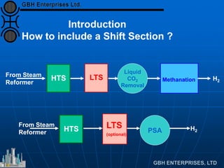
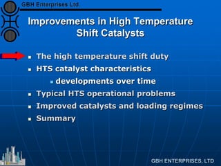
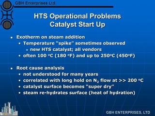
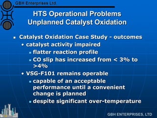
![HTS Catalyst - Addition of Copper
2. Over-reduction
CO2/CO phase equilibrium
Cu increases activity
• rapidly increases p[CO2]/decreases p[CO]
300 350 400 450 500 550
0.5
0.7
0.9
1.1
1.3
1.5
1.7
1.9
Temperature (oC)
P[CO2]/P[CO]
Fe
Fe3O4](https://image.slidesharecdn.com/htshightemperatureshift-comprehensievoverview-130729110953-phpapp02/85/HTS-High-Temperature-Shift-Catalyst-VSG-F101-Comprehensiev-Overview-19-320.jpg)
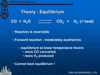
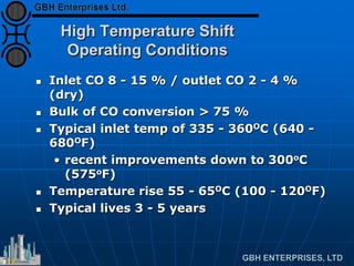
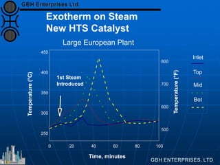
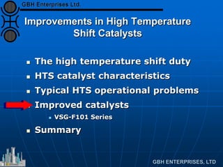
![HTS Catalyst - Addition of Copper
2. Over-reduction
H2O/H2 phase equilibrium
• rarely close to boundary
• Cu tends towards lower temperature
operation
300 350 400 450 500 550
0.1
0.2
0.3
0.5
0.7
1
Temperature (oC)
P[H2O]/P[H2]
Fe
Fe3O4
FeO](https://image.slidesharecdn.com/htshightemperatureshift-comprehensievoverview-130729110953-phpapp02/85/HTS-High-Temperature-Shift-Catalyst-VSG-F101-Comprehensiev-Overview-20-320.jpg)
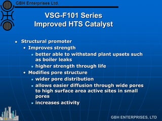
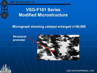
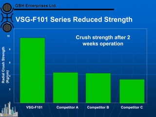
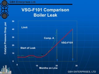
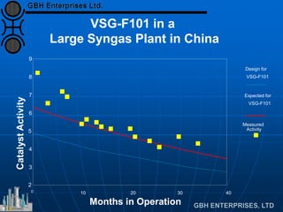
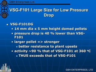
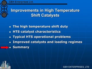
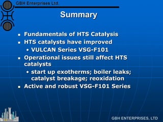


The document discusses improvements in high temperature shift catalysts. It describes the characteristics and operational issues of traditional HTS catalysts and how the new VULCAN Series VSG-F101 catalyst has addressed these issues through modifications to its microstructure and composition. The VSG-F101 has shown improved activity, strength, and resistance to thermal and mechanical stresses during plant upsets compared to previous catalysts.


![Capital Projects Assessment [Infographic]](https://cdn.slidesharecdn.com/ss_thumbnails/capitalprojectsassessment-130814143908-phpapp01-thumbnail.jpg?width=640&height=640&fit=bounds)


