Download as PDF, PPTX

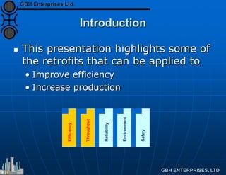
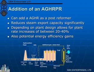
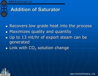
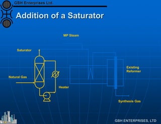
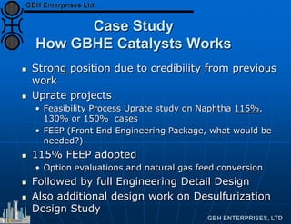


The document discusses retrofitting aging hydrogen plants to improve efficiency and production rates through various technical modifications, such as optimizing catalysts and steam ratios, adding pre-reformers, and redesigning exhaust systems. It highlights potential increases in performance, efficiency, and production, while also addressing the complexities and necessary considerations for successful implementations. GBHE Catalysts is positioned to provide comprehensive engineering and design support for these retrofitting projects.


