Downloaded 172 times
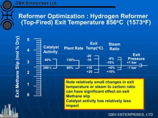
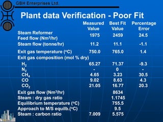
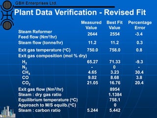
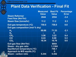
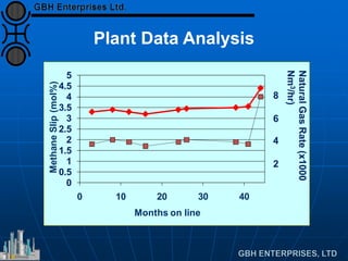
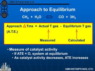
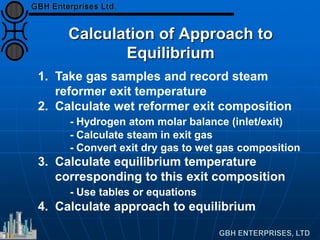
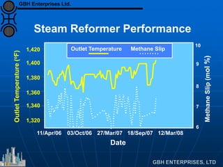
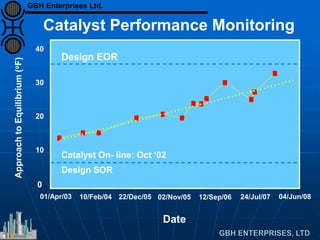
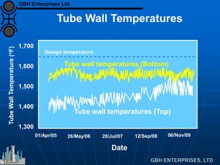
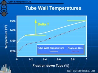
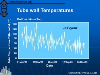
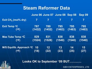
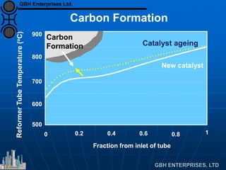
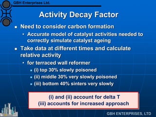
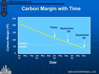
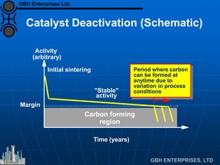
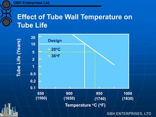
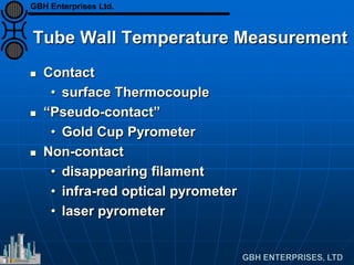
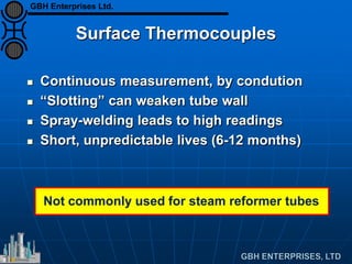
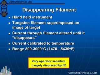

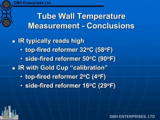

The document provides an overview of the operational parameters and data analysis necessary for the effective management of steam reformers in hydrogen plants. It includes details about performance metrics, catalyst life prediction, temperature measurements, and various optimization strategies, emphasizing the importance of accurate data collection and monitoring. The document also discusses the complexities of catalyst activity and interpretation of reformer analytics for maintaining efficient plant operations.


