Downloaded 120 times
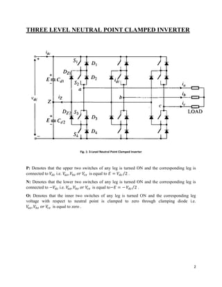
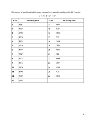
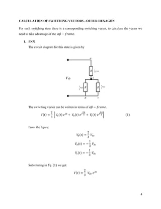


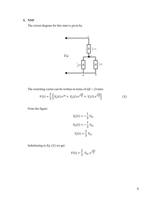
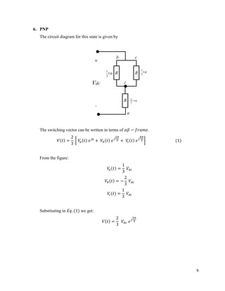
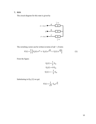
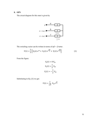

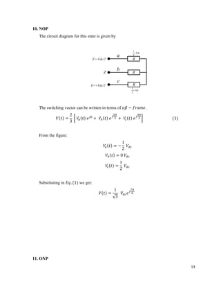
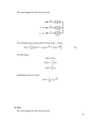
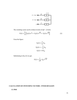
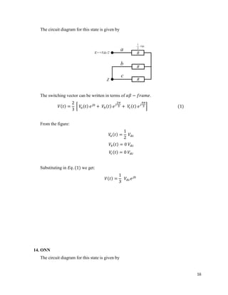


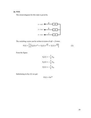

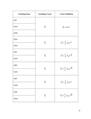
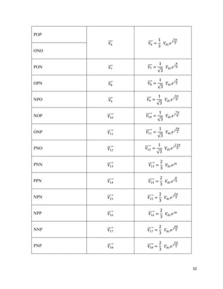
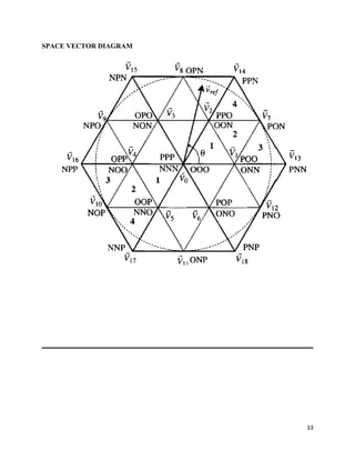

This document describes a three level neutral point clamped (NPC) inverter. It includes: 1. A diagram of the 3-level NPC inverter circuit and descriptions of the switching states. 2. Calculations of the switching vectors for each switching state by analyzing equivalent circuits. 3. Tables listing the 27 possible switching states and their corresponding switching vectors.


