Downloaded 40 times

![Conversion
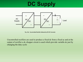
Uncontrolled Rectifier followed by DC-DC Chopper
Continuous
powergui
v
+
-
Voltage Measurement
Scope3
Scope
274.4
Rectified Voltage
In Mean
Mean Value1
In Mean
Mean Value
[A]
From1
Diode3
Diode2
Diode1
Diode
Conn1
Conn2
Converter
C3
12.05
Buck Output
AC Voltage Source
Rectifier followed by Chopper](https://image.slidesharecdn.com/converters-140412101723-phpapp01/85/Rectifiers-Simulation-10-320.jpg)
![Conversion
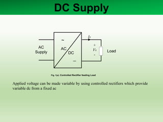
Uncontrolled Rectifier followed by DC-DC Chopper
2
Conn2
1
Conn1
t
v
+
-
Vo V
R
Pulse
Generator
In Mean
Mean Value2
L
i
+
-
Io
g
C
E
IGBT/Diode [A]
Goto1
1.03
Display1
D
Clock
C2C1
A
Chopper](https://image.slidesharecdn.com/converters-140412101723-phpapp01/85/Rectifiers-Simulation-11-320.jpg)
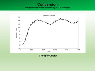
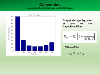
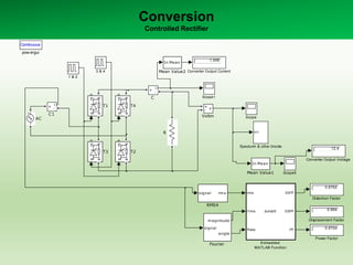
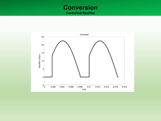
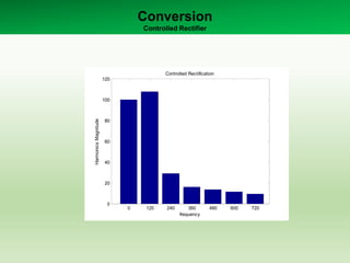
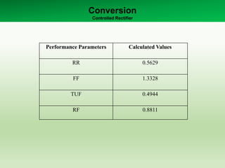


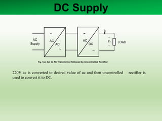
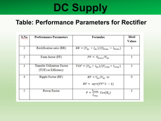
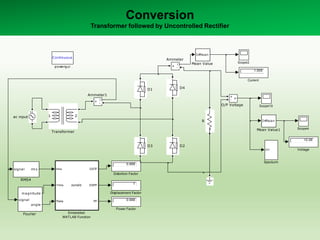
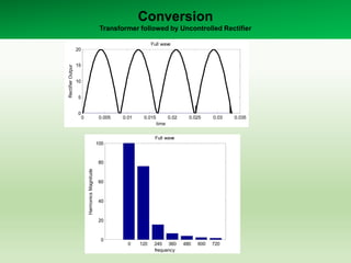
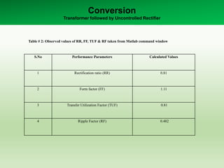
This document summarizes simulations of different DC supply converter circuits including: 1. An AC-AC transformer followed by an uncontrolled rectifier. 2. An uncontrolled rectifier followed by a DC-DC converter. 3. A controlled rectifier feeding a load. Tables show calculated performance parameters for the rectifiers including rectification ratio, form factor, transfer utilization factor, and ripple factor. Waveforms and harmonics analyses are also presented for outputs of the different converter configurations.


