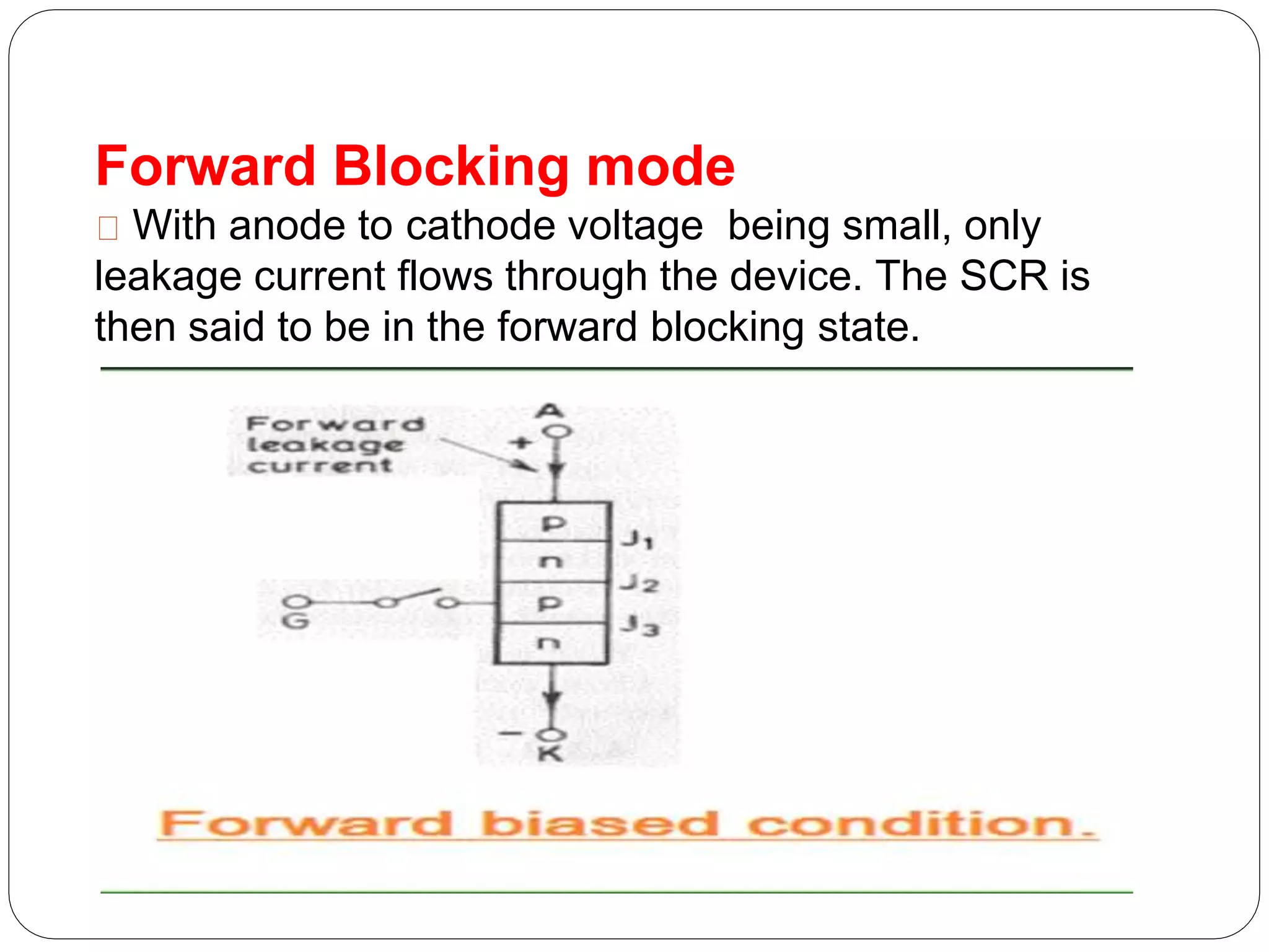
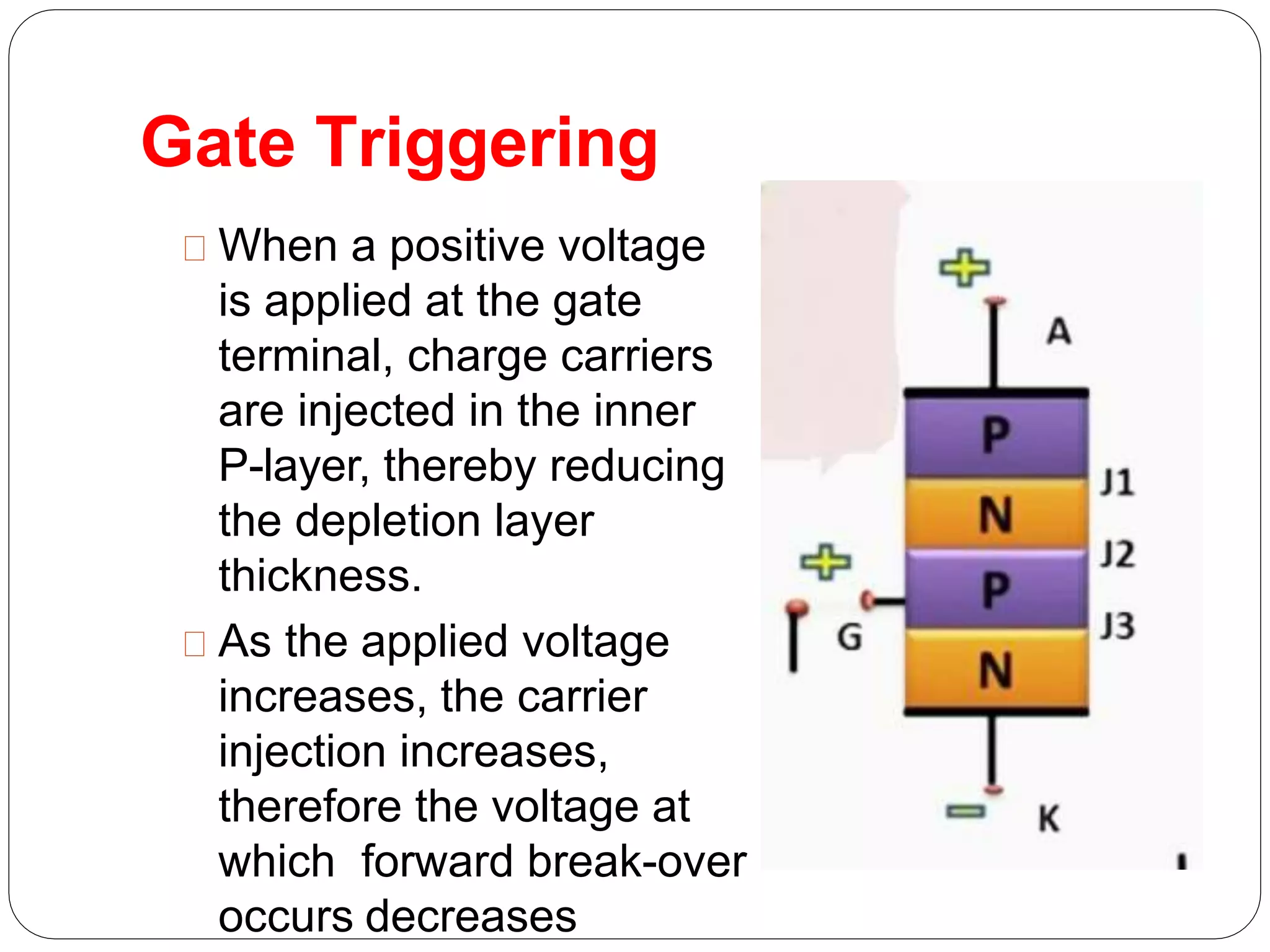
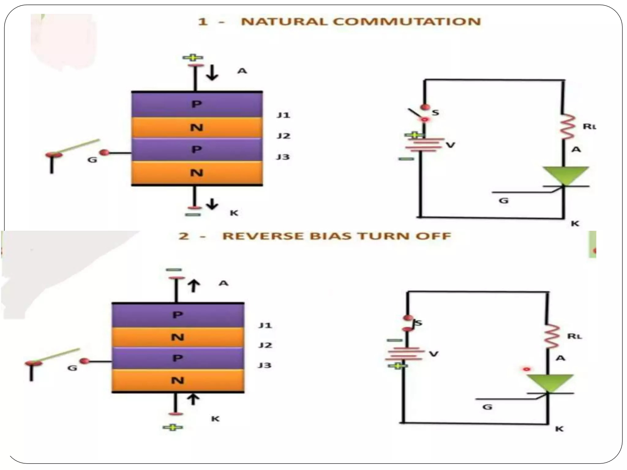
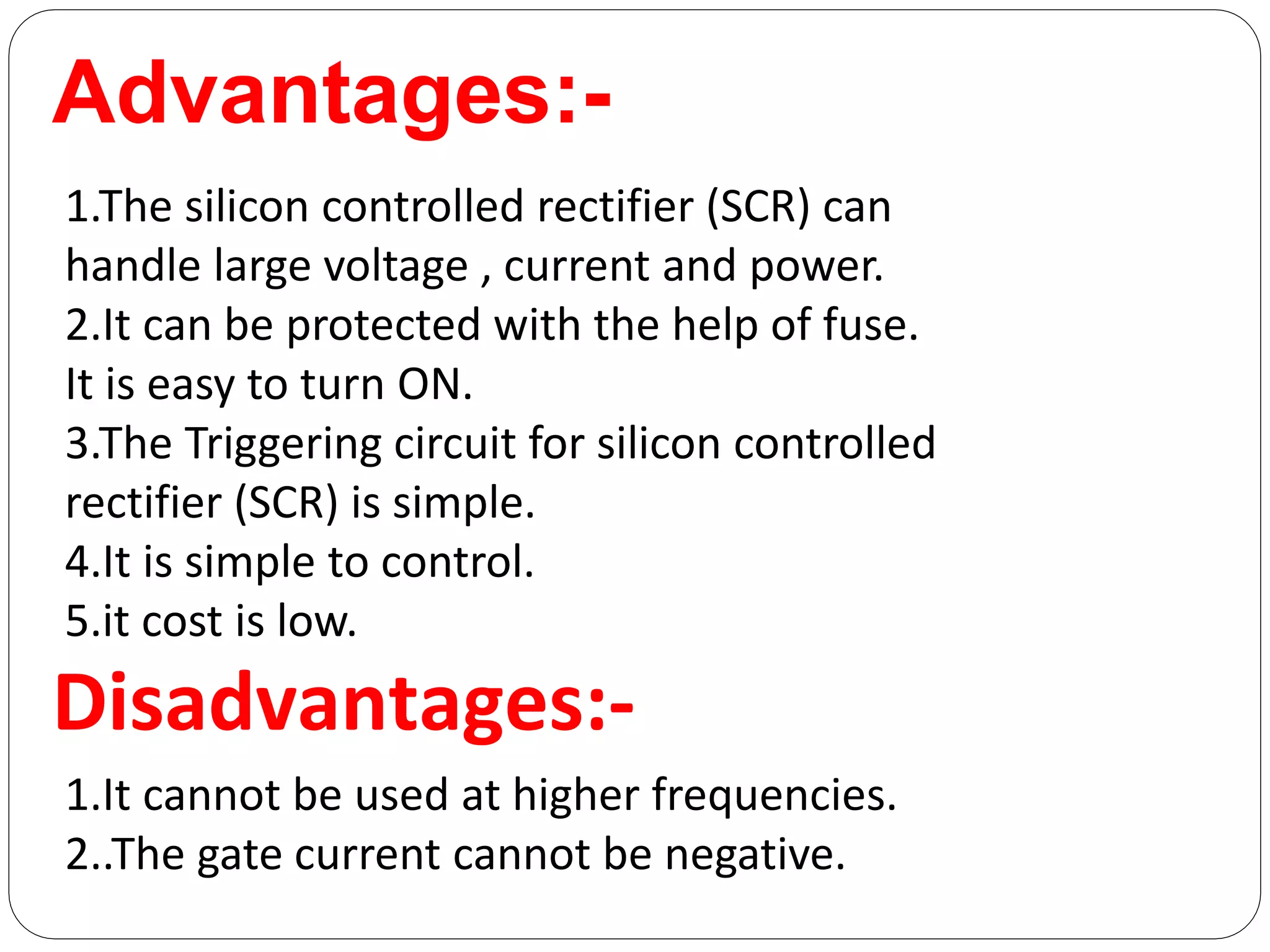
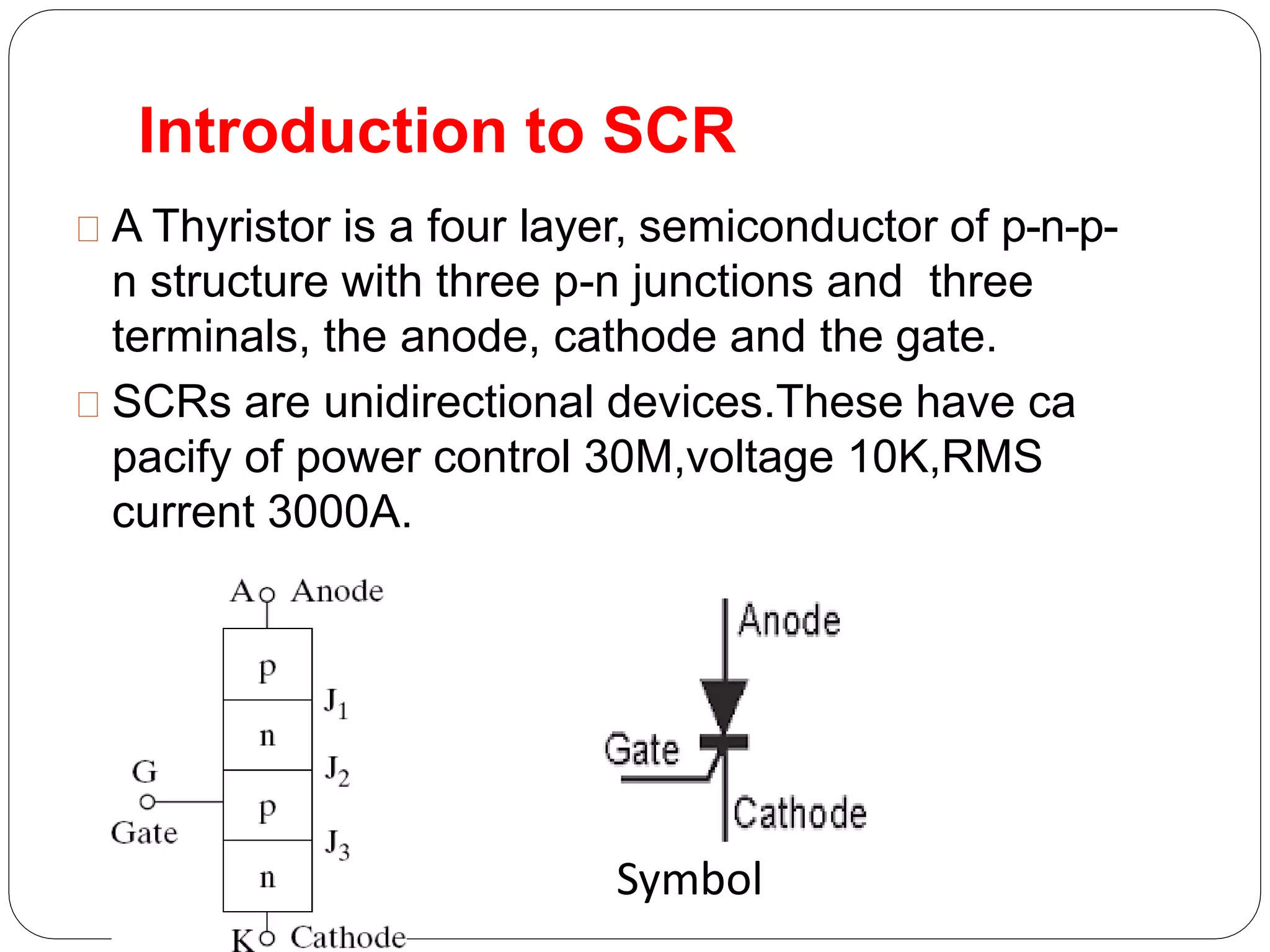
Silicon Controlled
Rectifier
Present by
Samala Ranjith
16311A0240
EEE
Contents
1.Introduction
2.history
3.construction
4.v-i characteristics
5.Switching on&off methods
6.Applications
7.Advantages
8.Disadvantages
9.Conclusion
Introduction to SCR
A Thyristor is a four layer, semiconductor of p-n-p-
n structure with three p-n junctions and three
terminals, the anode, cathode and the gate.
SCRs are unidirectional devices.These have ca
pacify of power control 30M,voltage 10K,RMS
current 3000A.
Symbol
History:-
The SCR was developed by a
team of power engineers led
by Gordon Hall[4] and
commercialized by Frank W.
"Bill" Gutzwiller in 1957.
Construction:-
SCR consists
1.four layers
2.3 junctions
V-I Characteristics of
SCR:-
Forward Blocking mode
With anode to cathode voltage being small, only
leakage current flows through the device. The SCR is
then said to be in the forward blocking state.
Forward conduction mode
Whenever the applied forward voltage is more
than the breakover voltage then SCR starts
conducting.
here,anode is connected to negative terminal
And cathode is connected to positive terminal of
battery.
Where the gate is disconnected.
Reverse Blocking Mode
THYRISTOR Triggering methods(on)
Forward Voltage triggering
Light triggering
dv/dt Triggering
Gate triggering
Thermal turn on(or) High temperature
triggering
SCR On&off methods
Forward Voltage Triggering
In this mode, an
additional forward voltage
is applied between
anode and cathode.
No current flows due to
depletion region in J2 is
reverse biased (except
leakage current).
Applied voltage>break
over voltage
This type of turn on
is destructive and
should be avoided.
Light Triggering
A niche is provided
instead of gate.
When light is allowed to
strike this terminal, electron
hole pairs are generated.
When intensity of light
becomes more than a
normal value, the
Thyristor starts
conducting.
This type of SCRs are called
as LASCR
dv/dt Triggering
When the device is forward
biased, J1 and J3 are
forward biased, J2 is
reverse biased.
Junction J2 behaves as
a capacitor, due to the
charges existing across
the junction.
Gate Triggering
When a positive voltage
is applied at the gate
terminal, charge carriers
are injected in the inner
P-layer, thereby reducing
the depletion layer
thickness.
As the applied voltage
increases, the carrier
injection increases,
therefore the voltage at
which forward break-over
occurs decreases
Thermal Turn on or High
Temperature
The width of depletion layer of SCR decreases
with increase in junction temperature.
By increasing the junction temperature the
reverse biased junction collapses thus the device
starts to conduct.
This type of turn on many cause thermal run
away and is usually avoided.
SCR off methods
1 . Natural communication
2.Reverse bias turn off method
3.Gate turn off method
The turn OFF process of an SCR is called
commutation. The term commutation means the
transfer of currents from one path to another.
Advantages:-
1.The silicon controlled rectifier (SCR) can
handle large voltage , current and power.
2.It can be protected with the help of fuse.
It is easy to turn ON.
3.The Triggering circuit for silicon controlled
rectifier (SCR) is simple.
4.It is simple to control.
5.it cost is low.
Disadvantages:-
1.It cannot be used at higher frequencies.
2..The gate current cannot be negative.
Conclusion:-
SCR is aPower electronic device.It controls high
voltages,currents.
Working in between 50 to 10k Hz frequency.
Controlling of SCR is very easy.Triggering
voltage is very less.
Silicon controlled rectifier

Silicon controlled rectifier

  • 1.
  • 2.
    Contents 1.Introduction 2.history 3.construction 4.v-i characteristics 5.Switching on&offmethods 6.Applications 7.Advantages 8.Disadvantages 9.Conclusion
  • 3.
    Introduction to SCR AThyristor is a four layer, semiconductor of p-n-p- n structure with three p-n junctions and three terminals, the anode, cathode and the gate. SCRs are unidirectional devices.These have ca pacify of power control 30M,voltage 10K,RMS current 3000A. Symbol
  • 4.
    History:- The SCR wasdeveloped by a team of power engineers led by Gordon Hall[4] and commercialized by Frank W. "Bill" Gutzwiller in 1957.
  • 5.
  • 6.
  • 7.
    Forward Blocking mode Withanode to cathode voltage being small, only leakage current flows through the device. The SCR is then said to be in the forward blocking state.
  • 8.
    Forward conduction mode Wheneverthe applied forward voltage is more than the breakover voltage then SCR starts conducting.
  • 9.
    here,anode is connectedto negative terminal And cathode is connected to positive terminal of battery. Where the gate is disconnected. Reverse Blocking Mode
  • 10.
    THYRISTOR Triggering methods(on) ForwardVoltage triggering Light triggering dv/dt Triggering Gate triggering Thermal turn on(or) High temperature triggering SCR On&off methods
  • 11.
    Forward Voltage Triggering Inthis mode, an additional forward voltage is applied between anode and cathode. No current flows due to depletion region in J2 is reverse biased (except leakage current). Applied voltage>break over voltage This type of turn on is destructive and should be avoided.
  • 12.
    Light Triggering A nicheis provided instead of gate. When light is allowed to strike this terminal, electron hole pairs are generated. When intensity of light becomes more than a normal value, the Thyristor starts conducting. This type of SCRs are called as LASCR
  • 13.
    dv/dt Triggering When thedevice is forward biased, J1 and J3 are forward biased, J2 is reverse biased. Junction J2 behaves as a capacitor, due to the charges existing across the junction.
  • 14.
    Gate Triggering When apositive voltage is applied at the gate terminal, charge carriers are injected in the inner P-layer, thereby reducing the depletion layer thickness. As the applied voltage increases, the carrier injection increases, therefore the voltage at which forward break-over occurs decreases
  • 15.
    Thermal Turn onor High Temperature The width of depletion layer of SCR decreases with increase in junction temperature. By increasing the junction temperature the reverse biased junction collapses thus the device starts to conduct. This type of turn on many cause thermal run away and is usually avoided.
  • 16.
    SCR off methods 1. Natural communication 2.Reverse bias turn off method 3.Gate turn off method The turn OFF process of an SCR is called commutation. The term commutation means the transfer of currents from one path to another.
  • 19.
    Advantages:- 1.The silicon controlledrectifier (SCR) can handle large voltage , current and power. 2.It can be protected with the help of fuse. It is easy to turn ON. 3.The Triggering circuit for silicon controlled rectifier (SCR) is simple. 4.It is simple to control. 5.it cost is low. Disadvantages:- 1.It cannot be used at higher frequencies. 2..The gate current cannot be negative.
  • 20.
    Conclusion:- SCR is aPowerelectronic device.It controls high voltages,currents. Working in between 50 to 10k Hz frequency. Controlling of SCR is very easy.Triggering voltage is very less.