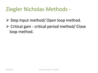
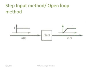
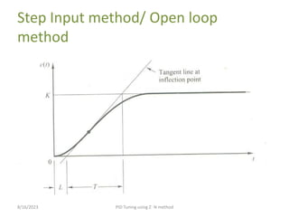
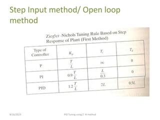
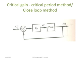
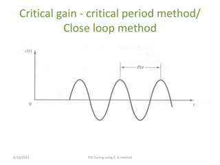
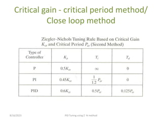
This presentation explains about the introduction of Bode Plot, advantages of bode plot and also steps to draw Bode plot (Magnitude plot and phase plot). It explains basic or key factors used for drawing Bode plot. It also explains how to determine Magnitude, phase and slope for basic factors. It also explains how to determine stability by using Bode Plot and also how to determine Gain Crossover Frequency and Phase Crossover Frequency, Gain Margin and Phase Margin. It also explains drawing Bode plot with an example and also determines stability by using Bode Plot and also determines Gain Crossover Frequency and Phase Crossover Frequency, Gain Margin and Phase Margin.
Root locus is a graphical representation of the closed-loop poles as a system parameter is varied.
It can be used to describe qualitatively the performance of a system as various parameters are changed.
It gives graphic representation of a system’s transient response and also stability.
We can see the range of stability, instability, and the conditions that cause a system to break into oscillation.
In this presentation we can get to know how we can construct a bode plot with suitable examples Of different -different orders.
Along with that a simulation model on MATLAB with graph.
And in this we have explained about the transfer function, poles & zeroes.And the basic concept of stability.
This presentation explains about the introduction of Nyquist Stability criterion. It clearly shows advantages and disadvantages of Nyquist Stability criterion and also explains importance of Nyquist Stability criterion and steps required to sketch the Nyquist plot. It explains about the steps required to sketch Nyquist plot clearly. It also explains about sketching Nyquist plot and determines the stability by using Nyquist Stability criterion with an example.
Introduction, Types of Stable System, Routh-Hurwitz Stability Criterion, Disadvantages of Hurwitz Criterion, Techniques of Routh-Hurwitz criterion, Examples, Special Cases of Routh Array, Advantages and Disadvantages of Routh-Hurwitz Stability Criterion, and examples.
Chapter 8 Pid controllers and modified pid controllers. From the book (Ogata Modern Control Engineering 5th).
8-1 introduction
8-2 Ziegler-Nichols rules for tuning pid controllers .
FPGA implementation of universal modulator using CORDIC algorithm for commun...IJMER
The modern communication systems and software radio based applications demands fully
digital receivers, consisting of only an antenna and a fully programmable circuit with digital modulators
and demodulators. A basic communication system’s transmitter modulates the amplitude, phase or
frequency proportional to the signal being transmitted. An efficient solution (that doesn’t require large
tables/memory) for realizing universal modulator is CORDIC (CO-ordinate Rotation Digital Computer)
algorithm. The CORDIC algorithm is used in the rotation mode, to convert the coordinates from polar
mode to rectangular mode. The radius vector(r) and angle (θ) of a CORDIC processor can be
programmed to generate the ASK, PSK and FSK signals. Modelsim simulator tool from mentor graphics
will be used for functional simulation and verification of the modulator. The Xilinx synthesis Tools (XST)
will be used to synthesize the complete modulator on Xilinx Spartan 3E family FPGA (XC3S500E). Xilinx
placement & routing tools will be used for backed, design optimization and I/O routing.
A Simplified Speed Control Of Induction Motor based on a Low Cost FPGA IJECEIAES
This paper investigates the development of a simplified speed control of induction motor based on indirect field oriented control (FOC). An original PI-P controller is designed to obtain good performances for speed tracking. Controller coefficients are carried out with analytic approach. The algorithm is implemented using a low cost Field Programmable Gate Array (FPGA). The implementation is followed by an efficient design methodology that offers considerable design advantages. The main advantage is the design of reusable and reconfigurable hardware modules for the control of electrical systems. Experimental results carried on a prototyping platform are given to illustrate the efficiency and the benefits of the proposed approach.
International Journal of Engineering Research and Applications (IJERA) is an open access online peer reviewed international journal that publishes research and review articles in the fields of Computer Science, Neural Networks, Electrical Engineering, Software Engineering, Information Technology, Mechanical Engineering, Chemical Engineering, Plastic Engineering, Food Technology, Textile Engineering, Nano Technology & science, Power Electronics, Electronics & Communication Engineering, Computational mathematics, Image processing, Civil Engineering, Structural Engineering, Environmental Engineering, VLSI Testing & Low Power VLSI Design etc.
Hierarchical Digital Twin of a Naval Power SystemKerry Sado
A hierarchical digital twin of a Naval DC power system has been developed and experimentally verified. Similar to other state-of-the-art digital twins, this technology creates a digital replica of the physical system executed in real-time or faster, which can modify hardware controls. However, its advantage stems from distributing computational efforts by utilizing a hierarchical structure composed of lower-level digital twin blocks and a higher-level system digital twin. Each digital twin block is associated with a physical subsystem of the hardware and communicates with a singular system digital twin, which creates a system-level response. By extracting information from each level of the hierarchy, power system controls of the hardware were reconfigured autonomously. This hierarchical digital twin development offers several advantages over other digital twins, particularly in the field of naval power systems. The hierarchical structure allows for greater computational efficiency and scalability while the ability to autonomously reconfigure hardware controls offers increased flexibility and responsiveness. The hierarchical decomposition and models utilized were well aligned with the physical twin, as indicated by the maximum deviations between the developed digital twin hierarchy and the hardware.
Welcome to WIPAC Monthly the magazine brought to you by the LinkedIn Group Water Industry Process Automation & Control.
In this month's edition, along with this month's industry news to celebrate the 13 years since the group was created we have articles including
A case study of the used of Advanced Process Control at the Wastewater Treatment works at Lleida in Spain
A look back on an article on smart wastewater networks in order to see how the industry has measured up in the interim around the adoption of Digital Transformation in the Water Industry.
Student information management system project report ii.pdfKamal Acharya
Our project explains about the student management. This project mainly explains the various actions related to student details. This project shows some ease in adding, editing and deleting the student details. It also provides a less time consuming process for viewing, adding, editing and deleting the marks of the students.
CFD Simulation of By-pass Flow in a HRSG module by R&R Consult.pptxR&R Consult
CFD analysis is incredibly effective at solving mysteries and improving the performance of complex systems!
Here's a great example: At a large natural gas-fired power plant, where they use waste heat to generate steam and energy, they were puzzled that their boiler wasn't producing as much steam as expected.
R&R and Tetra Engineering Group Inc. were asked to solve the issue with reduced steam production.
An inspection had shown that a significant amount of hot flue gas was bypassing the boiler tubes, where the heat was supposed to be transferred.
R&R Consult conducted a CFD analysis, which revealed that 6.3% of the flue gas was bypassing the boiler tubes without transferring heat. The analysis also showed that the flue gas was instead being directed along the sides of the boiler and between the modules that were supposed to capture the heat. This was the cause of the reduced performance.
Based on our results, Tetra Engineering installed covering plates to reduce the bypass flow. This improved the boiler's performance and increased electricity production.
It is always satisfying when we can help solve complex challenges like this. Do your systems also need a check-up or optimization? Give us a call!
Work done in cooperation with James Malloy and David Moelling from Tetra Engineering.
More examples of our work https://www.r-r-consult.dk/en/cases-en/
1. PID Tuning using Ziegler-Nichols
Method
Subject – Control System
Kaustubha H. Shedbalkar
8/16/2023 PID Tuning using Z- N method
2. Ziegler Nicholas Methods -
Step Input method/ Open loop method.
Critical gain - critical period method/ Close
loop method.
8/16/2023 PID Tuning using Z- N method
3. Step Input method/ Open loop
method
8/16/2023 PID Tuning using Z- N method
4. Step Input method/ Open loop
method
8/16/2023 PID Tuning using Z- N method
5. • In this method, we obtain experimentally the
response of the plant as shown in fig. This method
applies if the response to a step input exhibits an
S-Shaped curve.
• The S-Shaped curve may be characterized by two
constants, Delay time (L) & Time constant (T). It is
determined by drawing a tangent line at the
inflection point of S-Shaped curve & determining
the intersection of tangent line with time axis &
line K on Y-axis. The Ziegler-Nichols suggested, we
set the value of parameter Kp, Ti, Td according to
the formula shown in table.
8/16/2023 PID Tuning using Z- N method
6. Step Input method/ Open loop
method
8/16/2023 PID Tuning using Z- N method
7. Critical gain - critical period method/
Close loop method
8/16/2023 PID Tuning using Z- N method
8. Critical gain - critical period method/
Close loop method
8/16/2023 PID Tuning using Z- N method
9. 8/16/2023 PID Tuning using Z- N method
• In this method, suppose PID controller is used in
the system then Ti is set to infinity & Td is set to
zero. Using proportional control action only,
increase Kp from zero to critical value Kcr at which
the output first exhibits sustained oscillations.
• The critical gain Kcr & corresponding time period
Pcr are determined.
•The Ziegler-Nichols suggested, we set the value of
parameter Kp, Ti, Td according to the formula
shown in table.
10. Critical gain - critical period method/
Close loop method
8/16/2023 PID Tuning using Z- N method