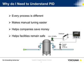
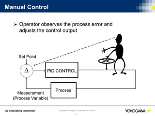
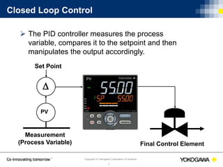
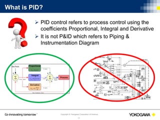
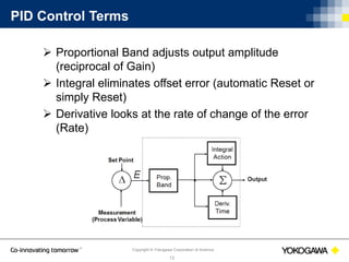
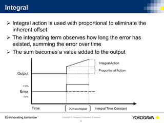
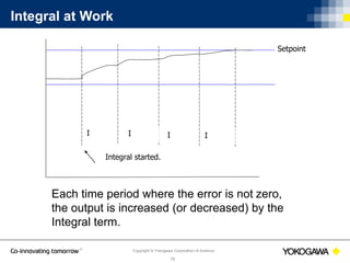
Copyright © Yokogawa Corporation of America
1
PID Control Basics
PID Tuning
Rob Sink
Technical Support Specialist
June 14th, 2016
Copyright © Yokogawa Corporation of America
2
What will be covered:
1. Common Process Control Techniques
2. Process Dynamics
3. What is PID
4. PID Control Components
5. How to Tune a PID Loop
Copyright © Yokogawa Corporation of America
3
Why do I Need to Understand PID
 Every process is different
 Makes manual tuning easier
 Helps companies save money
 Helps facilities remain safe
Copyright © Yokogawa Corporation of America
4
Common Process Control Techniques
ques
 Manual Control
 ON / OFF Control
 Closed Loop Control
Copyright © Yokogawa Corporation of America
5
Manual Control
 Operator observes the process error and
adjusts the control output
 PID CONTROL
Set Point
Measurement
(Process Variable)
Process
Copyright © Yokogawa Corporation of America
6
ON / OFF Control
 Simplest form of feed back control
 Can be used for processes not requiring extremely tight
control
Copyright © Yokogawa Corporation of America
7
Closed Loop Control
 The PID controller measures the process
variable, compares it to the setpoint and then
manipulates the output accordingly.
Final Control Element

PV
Set Point
Measurement
(Process Variable)
Copyright © Yokogawa Corporation of America
8
Process Dynamics: Dead Time
 Dead time is defined as the time before the process variable
BEGINS to react to a change in the control output
Output
Process
Variable
Lag Time
Dead
Time
Copyright © Yokogawa Corporation of America
9
Process Dynamics: Lag Time
 Lag is defined as the time required for the process
variable to adjust to a steady state after an output change
is performed
 Lag time affects the control action
Output
Process
Variable
Lag Time
Copyright © Yokogawa Corporation of America
10
Process Dynamics: Output vs. Process Change
Copyright © Yokogawa Corporation of America
11
What is PID?
 PID control refers to process control using the
coefficients Proportional, Integral and Derivative
 It is not P&ID which refers to Piping &
Instrumentation Diagram
Copyright © Yokogawa Corporation of America
12
PID Control Defined
 PID control can be
described as a set of rules
with which a precise
regulation of a closed-
loop control system is
obtained.
Temp
(PV)
Temp
Setpoint
(SP)
Copyright © Yokogawa Corporation of America
13
PID Control Terms
 Proportional Band adjusts output amplitude
(reciprocal of Gain)
 Integral eliminates offset error (automatic Reset or
simply Reset)
 Derivative looks at the rate of change of the error
(Rate)
Copyright © Yokogawa Corporation of America
14
Proportional Band
 The Proportional Band (P) is defined as the range over
which the control output is adjusted from 0-100%
 Proportional does the heavy lifting getting the temperature
close to the setpoint
 Some manufacturers use Gain instead of Proportional
Band
Copyright © Yokogawa Corporation of America
15
Proportional with Manual Reset
 With proportional only control, an offset will be
present between set point and process variable.
 Manual Reset allows a user to bias or shift the
output to compensate for the steady state offset.
1000º
Manual Reset Adjusted Here
500º
Set Point
Proportional
Band
Time
Copyright © Yokogawa Corporation of America
16
Integral
 Integral action is used with proportional to eliminate the
inherent offset
 The integrating term observes how long the error has
existed, summing the error over time
 The sum becomes a value added to the output
Output
Time 200 sec/repeat
Integral Action
Proportional Action
Integral Time Constant
Error
-10%
+10%
Copyright © Yokogawa Corporation of America
17
Integral – cont.
 Engineering units:
Repeats/minute
Minutes/repeat
Seconds/repeat
 The integral action ceases at a no error condition
Copyright © Yokogawa Corporation of America
18
Integral at Work
I I II
Integral started.
Setpoint
Each time period where the error is not zero,
the output is increased (or decreased) by the
Integral term.
Copyright © Yokogawa Corporation of America
19
A Note About Integral Windup
 Integral windup refers to the situation in a PID controller
where the integral, or reset action continues to integrate
(ramp) indefinitely
 This usually occurs when the controller's output can no
longer affect the controlled variable, which in turn can be
caused by controller saturation
 Typical causes of Integral Windup are: The input has been
removed from the process, output device has failed, a
furnace door has been opened keeping the process from
reaching temperature
Copyright © Yokogawa Corporation of America
20
Derivative
 Engineering units: minutes or seconds
 Anticipates the error rate and applies the “brakes”
 Derivative has no effect if the error is constant
Output
Time 50 seconds
Derivative Action
Integral Action
Derivative Time Constant
Error
-10%
+10%
Copyright © Yokogawa Corporation of America
21
P, I and D Working Together
P only P and I P I D
Copyright © Yokogawa Corporation of America
22
How to Tune a PID Loop
 Manually tuning the loop
 Using the controllers Auto/Self Tune
Copyright © Yokogawa Corporation of America
23
Manually Tuning a Loop
 These values are good starting points
 Change only (1) term at a time
 Make small changes observing the result
Copyright © Yokogawa Corporation of America
24
Fine-tuning the Proportional Band
 Work from larger to smaller numbers (wider to narrower)
 If cycling appears, the proportional band is too narrow
Copyright © Yokogawa Corporation of America
25
Fine Tuning the Integral Time
 The main goal is to reduce the offset
 Adjust from longer to shorter time
 If an oscillation exists at a longer period then the
integral time is too short
Copyright © Yokogawa Corporation of America
26
Fine Tuning the Derivative Time
 Adjust from shorter to longer time
 If short-period oscillations develop, the time is to long.
 The larger the Derivative, the stronger the corrective
action and the more likely the output will become
oscillatory
Copyright © Yokogawa Corporation of America
27
Tuning Loops with Dead Time
Output
Process
Variable
Lag Time
Dead
Time
Set P to 5% and the I & D to 0%
Start the process with a setpoint that will allow the
process variable to stabilize
Copyright © Yokogawa Corporation of America
28
Tuning Fast Reacting Loops
Set P to 100% and the I & D to 0%
Start the process with a setpoint that will allow the
process variable to stabilize
Copyright © Yokogawa Corporation of America
29
Using Auto Tune to Determine PID Values
 The output is varied between 0% and 100% three
times (these values may be limited).
 The process variable must ascend and descend
through set point for the output to change state.
 The auto tune algorithm observes the PV response
to these output changes and installs the appropriate
PID terms.
Copyright © Yokogawa Corporation of America
30
Ways to Prevent Overshoot
 Limit the working output or enable an output ramp
rate (if available)
 Limit the output range which will have an effect on the
time it takes to get to setpoint
 Ramp the setpoint at a slow rate
 Use fuzzy logic (if available)
Copyright © Yokogawa Corporation of America
31
Fuzzy Logic
 Fuzzy logic is used to help reduce setpoint overshoot
 Used in addition to PID control
Copyright © Yokogawa Corporation of America
32
Yokogawa Products that Use PID Control
Single loop controller
Programmable
controller
PLC
DCSPLC/RTU
Copyright © Yokogawa Corporation of America
33
UTAdvanced Line of controllers
 1-2 loops of control
 Built in ladder sequence control
 Software used in Webinar
 Nuclear qualified
Copyright © Yokogawa Corporation of America
34
YS1000 Family of Controllers
 1-2 loops of control
 Nuclear qualified
 Hard manual backup
 Function block programming
Copyright © Yokogawa Corporation of America
35
FA-M3 PLC
 Modular PLC design
 4 control loops per PID module
 PID control is not done in ladder logic
Copyright © Yokogawa Corporation of America
36
Questions
Questions?
Feel free to email us with further questions
at support@us.yokogawa.com.
Please put “PID Webinar” in the subject line.
Copyright © Yokogawa Corporation of America
37
Thank you for attending!
Feel free to email us with further questions
at support@us.yokogawa.com.
Please put “PID Webinar” in the subject line.

PID Control Basics

  • 1.
    Copyright © YokogawaCorporation of America 1 PID Control Basics PID Tuning Rob Sink Technical Support Specialist June 14th, 2016
  • 2.
    Copyright © YokogawaCorporation of America 2 What will be covered: 1. Common Process Control Techniques 2. Process Dynamics 3. What is PID 4. PID Control Components 5. How to Tune a PID Loop
  • 3.
    Copyright © YokogawaCorporation of America 3 Why do I Need to Understand PID  Every process is different  Makes manual tuning easier  Helps companies save money  Helps facilities remain safe
  • 4.
    Copyright © YokogawaCorporation of America 4 Common Process Control Techniques ques  Manual Control  ON / OFF Control  Closed Loop Control
  • 5.
    Copyright © YokogawaCorporation of America 5 Manual Control  Operator observes the process error and adjusts the control output  PID CONTROL Set Point Measurement (Process Variable) Process
  • 6.
    Copyright © YokogawaCorporation of America 6 ON / OFF Control  Simplest form of feed back control  Can be used for processes not requiring extremely tight control
  • 7.
    Copyright © YokogawaCorporation of America 7 Closed Loop Control  The PID controller measures the process variable, compares it to the setpoint and then manipulates the output accordingly. Final Control Element  PV Set Point Measurement (Process Variable)
  • 8.
    Copyright © YokogawaCorporation of America 8 Process Dynamics: Dead Time  Dead time is defined as the time before the process variable BEGINS to react to a change in the control output Output Process Variable Lag Time Dead Time
  • 9.
    Copyright © YokogawaCorporation of America 9 Process Dynamics: Lag Time  Lag is defined as the time required for the process variable to adjust to a steady state after an output change is performed  Lag time affects the control action Output Process Variable Lag Time
  • 10.
    Copyright © YokogawaCorporation of America 10 Process Dynamics: Output vs. Process Change
  • 11.
    Copyright © YokogawaCorporation of America 11 What is PID?  PID control refers to process control using the coefficients Proportional, Integral and Derivative  It is not P&ID which refers to Piping & Instrumentation Diagram
  • 12.
    Copyright © YokogawaCorporation of America 12 PID Control Defined  PID control can be described as a set of rules with which a precise regulation of a closed- loop control system is obtained. Temp (PV) Temp Setpoint (SP)
  • 13.
    Copyright © YokogawaCorporation of America 13 PID Control Terms  Proportional Band adjusts output amplitude (reciprocal of Gain)  Integral eliminates offset error (automatic Reset or simply Reset)  Derivative looks at the rate of change of the error (Rate)
  • 14.
    Copyright © YokogawaCorporation of America 14 Proportional Band  The Proportional Band (P) is defined as the range over which the control output is adjusted from 0-100%  Proportional does the heavy lifting getting the temperature close to the setpoint  Some manufacturers use Gain instead of Proportional Band
  • 15.
    Copyright © YokogawaCorporation of America 15 Proportional with Manual Reset  With proportional only control, an offset will be present between set point and process variable.  Manual Reset allows a user to bias or shift the output to compensate for the steady state offset. 1000º Manual Reset Adjusted Here 500º Set Point Proportional Band Time
  • 16.
    Copyright © YokogawaCorporation of America 16 Integral  Integral action is used with proportional to eliminate the inherent offset  The integrating term observes how long the error has existed, summing the error over time  The sum becomes a value added to the output Output Time 200 sec/repeat Integral Action Proportional Action Integral Time Constant Error -10% +10%
  • 17.
    Copyright © YokogawaCorporation of America 17 Integral – cont.  Engineering units: Repeats/minute Minutes/repeat Seconds/repeat  The integral action ceases at a no error condition
  • 18.
    Copyright © YokogawaCorporation of America 18 Integral at Work I I II Integral started. Setpoint Each time period where the error is not zero, the output is increased (or decreased) by the Integral term.
  • 19.
    Copyright © YokogawaCorporation of America 19 A Note About Integral Windup  Integral windup refers to the situation in a PID controller where the integral, or reset action continues to integrate (ramp) indefinitely  This usually occurs when the controller's output can no longer affect the controlled variable, which in turn can be caused by controller saturation  Typical causes of Integral Windup are: The input has been removed from the process, output device has failed, a furnace door has been opened keeping the process from reaching temperature
  • 20.
    Copyright © YokogawaCorporation of America 20 Derivative  Engineering units: minutes or seconds  Anticipates the error rate and applies the “brakes”  Derivative has no effect if the error is constant Output Time 50 seconds Derivative Action Integral Action Derivative Time Constant Error -10% +10%
  • 21.
    Copyright © YokogawaCorporation of America 21 P, I and D Working Together P only P and I P I D
  • 22.
    Copyright © YokogawaCorporation of America 22 How to Tune a PID Loop  Manually tuning the loop  Using the controllers Auto/Self Tune
  • 23.
    Copyright © YokogawaCorporation of America 23 Manually Tuning a Loop  These values are good starting points  Change only (1) term at a time  Make small changes observing the result
  • 24.
    Copyright © YokogawaCorporation of America 24 Fine-tuning the Proportional Band  Work from larger to smaller numbers (wider to narrower)  If cycling appears, the proportional band is too narrow
  • 25.
    Copyright © YokogawaCorporation of America 25 Fine Tuning the Integral Time  The main goal is to reduce the offset  Adjust from longer to shorter time  If an oscillation exists at a longer period then the integral time is too short
  • 26.
    Copyright © YokogawaCorporation of America 26 Fine Tuning the Derivative Time  Adjust from shorter to longer time  If short-period oscillations develop, the time is to long.  The larger the Derivative, the stronger the corrective action and the more likely the output will become oscillatory
  • 27.
    Copyright © YokogawaCorporation of America 27 Tuning Loops with Dead Time Output Process Variable Lag Time Dead Time Set P to 5% and the I & D to 0% Start the process with a setpoint that will allow the process variable to stabilize
  • 28.
    Copyright © YokogawaCorporation of America 28 Tuning Fast Reacting Loops Set P to 100% and the I & D to 0% Start the process with a setpoint that will allow the process variable to stabilize
  • 29.
    Copyright © YokogawaCorporation of America 29 Using Auto Tune to Determine PID Values  The output is varied between 0% and 100% three times (these values may be limited).  The process variable must ascend and descend through set point for the output to change state.  The auto tune algorithm observes the PV response to these output changes and installs the appropriate PID terms.
  • 30.
    Copyright © YokogawaCorporation of America 30 Ways to Prevent Overshoot  Limit the working output or enable an output ramp rate (if available)  Limit the output range which will have an effect on the time it takes to get to setpoint  Ramp the setpoint at a slow rate  Use fuzzy logic (if available)
  • 31.
    Copyright © YokogawaCorporation of America 31 Fuzzy Logic  Fuzzy logic is used to help reduce setpoint overshoot  Used in addition to PID control
  • 32.
    Copyright © YokogawaCorporation of America 32 Yokogawa Products that Use PID Control Single loop controller Programmable controller PLC DCSPLC/RTU
  • 33.
    Copyright © YokogawaCorporation of America 33 UTAdvanced Line of controllers  1-2 loops of control  Built in ladder sequence control  Software used in Webinar  Nuclear qualified
  • 34.
    Copyright © YokogawaCorporation of America 34 YS1000 Family of Controllers  1-2 loops of control  Nuclear qualified  Hard manual backup  Function block programming
  • 35.
    Copyright © YokogawaCorporation of America 35 FA-M3 PLC  Modular PLC design  4 control loops per PID module  PID control is not done in ladder logic
  • 36.
    Copyright © YokogawaCorporation of America 36 Questions Questions? Feel free to email us with further questions at support@us.yokogawa.com. Please put “PID Webinar” in the subject line.
  • 37.
    Copyright © YokogawaCorporation of America 37 Thank you for attending! Feel free to email us with further questions at support@us.yokogawa.com. Please put “PID Webinar” in the subject line.

Editor's Notes

  • #6 In manual control, an operator monitors the difference between the process variable and the setpoint. The operator then makes changes to the control output to reduce or eliminate the error.
  • #7 ON/Off control is the simplest form of feedback control. In this type of control, the output is driven from fully closed to fully open depending on the relationship of the process variable to the setpoint and hysteresis. Every one listening today has experience with the thermostat in their home which is a common example of simple on off control.
  • #8 PID control is a form of closed loop control. In closed loop control, the process variable (PV) is measured and compared to the desired value called setpoint (SP). The controller changes it’s output, or manipulated variable (MV), until the measured variable equals the setpoint. Because process dynamics vary greatly and the controllers are made to be universal, controllers muse be TUNED to match the process.
  • #9 For example, let’s say we have a large tank of liquid for which we are controlling the temperature. When the output comes on, if there is no change in temperature for 10 minutes, then the dead time of the process is 10 minutes.
  • #11 In a direct acting process, as the PV increase towards the SP, the output also increases. A common direct acting process is chiller being used for air conditioning. In a reverse acting process, as the PV increases towards the SP, the output decreases. Flow control, furnaces, and pressure are all examples of direct acting processes.
  • #13 The concept of PID control and the terms associated with it will be the same whether we are talking about simple single loop controllers, more advanced programmable controllers, PLC’s and distributed control systems.
  • #14 Put simply: The proportional band adjusts the output amplitude. The integral reduces or eliminates any error between the setpoint and process variable. And the Derivative monitors the rate of change of the error in an attempt to anticipate process upsets.
  • #15 Proportional Band is expressed as a % of the full operating span of the controller and is centered around the SP assuming that the manual reset is set to 50%. For example, an operating range of 0-1,000° with a P of 5%, would equal a P of 50° straddled 25° above and below the setpoint. Let’s say that this is a reverse acting process like a furnace with a SP of 500. If the PV drops to 475° or below, the output will go to 100%. Similarly, if the PV rises to 525 or above, the output will go to 0%. The output will stay at these extreme values until the PV re-enters the proportional band between 475 and 525. When the temperature is within the proportional band, the output is PORTIONAL to the error.
  • #16 Using proportional only control, once the optimum proportional band is set, the process variable will be offset from the setpoint. Manual reset can them be used to shift the control output to compensate for the offset. Manual reset is available on all Yokogawa controllers, with a default to 50%. Using manual reset doesn’t provide very stable control. As parameters in the environment, or process system changes through the day, the process variable can drift. To prevent having to constantly change the setpoint, we need an automatic reset.
  • #18 The smaller the integral number the more often the proportional action we be repeated. If integral is too small, the process variable will oscillate through the set point and create erratic control action. If the number is too large, the action will be sluggish and unable to compensate for process upsets. The integral number should be approximately 5 times the dead/lag time of the process variable.
  • #19 The integral term continues to increase or decrease the output until a zero error condition is obtained.
  • #20 Sometimes referred to as reset windup, integral windup occurs when the integral action continues to add to the control output past the operational range of the valve, variable speed drive, heater, etc. (READ LAST POINT ON SLIDE)
  • #21 Derivative can simply be thought of as a prediction of the error in the future based on the time set.
  • #25 Gradually reduce P from a larger value. When the PV begins to oscillate, stop tuning and increase P slightly.
  • #26 Gradually reduce I from a larger value. When the PV begins to oscillate, as with P, stop tuning and increase I slightly.
  • #27 Gradually increase D from a smaller value. When the PV begins to oscillate, stop tuning and lower the value slightly.
  • #28 Temperature loops typically have considerable dead time.
  • #29 Fast loops are defined as having little or no deadtime or lag. Most fast loops are configured as a PI controller., proportional and integral terms only. This is because the derivative term is an overshoot/undershoot suppression function and naturally contributes to instability in a fast control loop.
  • #30 Sometimes Auto Tune can’t be used or shouldn’t be used. They include: Fast responding processes such as flow rate and pressure control A process that does not allow the output to be turned on and off even temporarily Processes in which product quality can be adversely affected if the PV values fluctuate beyond their allowable range. Temperature processes where there are adjacent temperature zones that affect each other, for example a plastic extruder. Let’s give Auto Tune a try. Again, I am simulating a furnace application using a Type K thermocouple and 4-20mA control output to simulate a gas valve. The temperature range is set to 100-600°F.
  • #31 One problem that you will encounter when tuning is SP overshoot. Setpoint Ramp - Some controllers and control systems have a feature called setpoint ramping. This feature allows a change of setpoint to be made in either engineering units/min or hour. Using this feature reduces the size of the error between the SP and the PV at each ramp thus requiring less output to be used. This in turn will help to prevent overshoot.
  • #32 Fuzzy Logic monitors the deviation for evidence of the danger of overshoot. Once this danger is sensed, the setpoint is temporarily changed to a somewhat lower value (sub-SP). Once the danger of overshoot appears reduced, the function returns the effective SP gradually to the true SP.