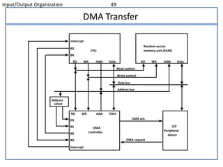
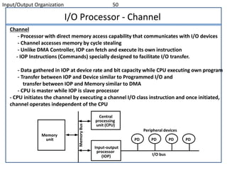
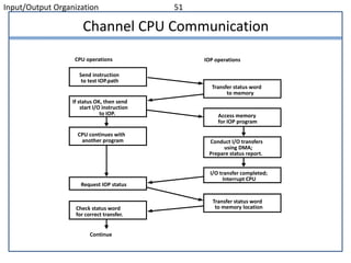
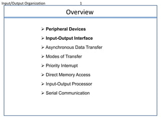
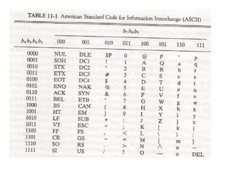
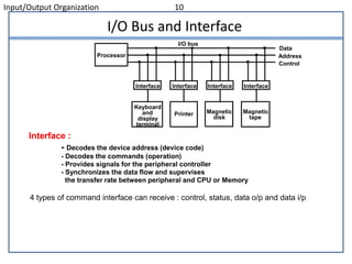
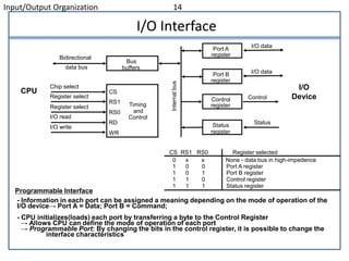
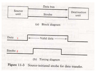
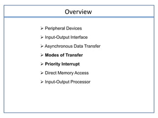
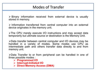
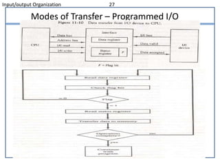
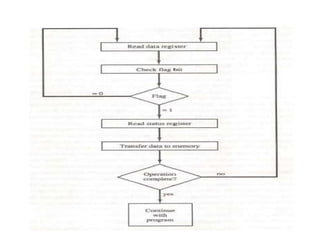
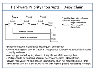
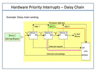
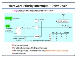
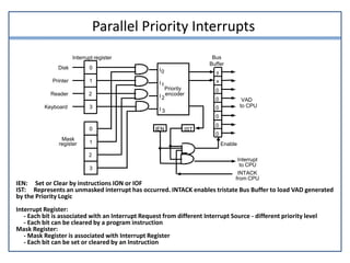
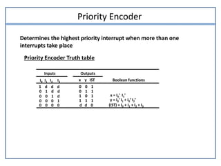
The document discusses input/output organization. It covers peripheral devices, input-output interfaces, asynchronous data transfer, modes of transfer including programmed I/O, interrupt-initiated I/O, and direct memory access (DMA), priority interrupts, and input-output processors. Specifically, it describes how priority interrupts work using both software polling and hardware daisy chaining approaches, and how parallel priority interrupts use an interrupt register, mask register, and priority encoder to determine the highest priority interrupt request.
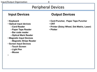

![Interrupt Cycle
At the end of each Instruction cycle
- CPU checks IEN and IST
- If IEN IST = 1, CPU -> Interrupt Cycle
SP SP - 1 Decrement stack pointer
M[SP] PC Push PC into stack
INTACK 1 Enable interrupt acknowledge
PC VAD Transfer vector address to PC
IEN 0 Disable further interrupts
Go To Fetch to execute the first instruction
in the interrupt service routine](https://image.slidesharecdn.com/chapter11-200907163718/85/Peripheral-devices-41-320.jpg)
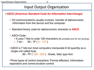
![Initial and Final Operations
JMP PTR
JMP RDR
JMP KBD
JMP DISK0
1
2
3
Program to service
magnetic disk
Program to service
line printer
Program to service
character reader
Program to service
keyboard
DISK
PTR
RDR
KBD
255
256
750
256
750
Stack
Main program
current instr.749
KBD
interrupt
2
VAD=00000011 3
4
Disk
interrupt
5
6
7
8
9 10
11
1
Initial and Final Operations
Each interrupt service routine must have an initial and final set of
operations for controlling the registers in the hardware interrupt system
Initial Sequence
[1] Clear lower level Mask reg. bits
[2] IST <- 0
[3] Save contents of CPU registers
[4] IEN <- 1
[5] Go to Interrupt Service Routine
Final Sequence
[1] IEN <- 0
[2] Restore CPU registers
[3] Clear the bit in the Interrupt Reg
[4] Set lower level Mask reg. bits
[5] Restore return address, IEN <- 1](https://image.slidesharecdn.com/chapter11-200907163718/85/Peripheral-devices-42-320.jpg)