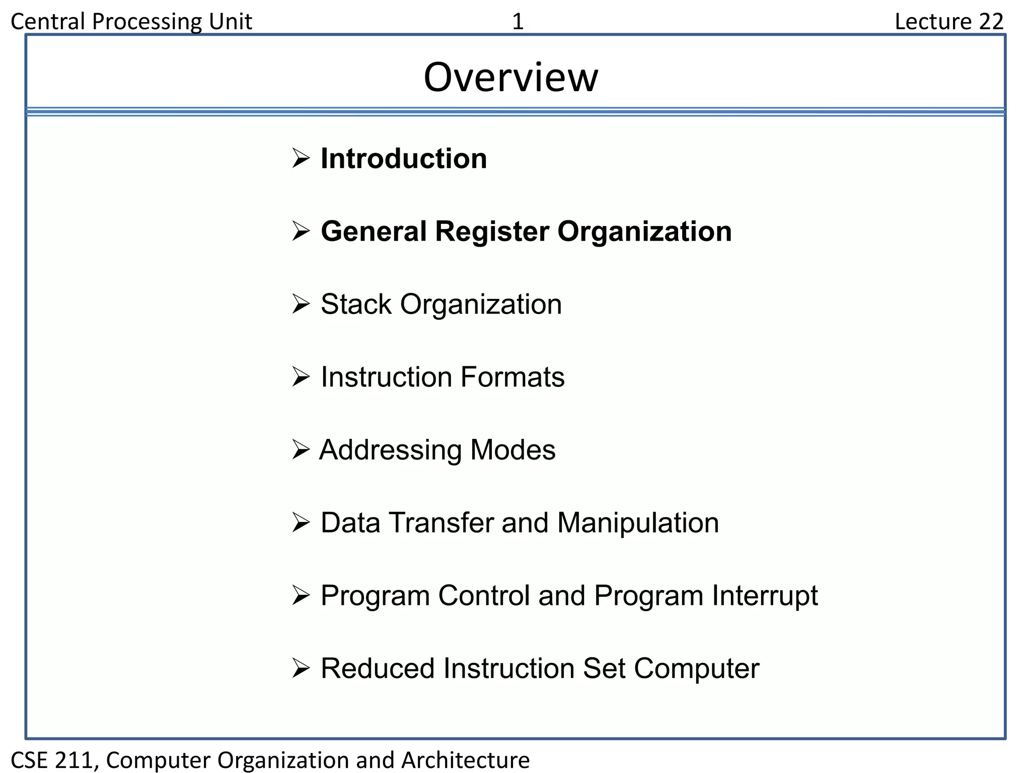
Structural Analysis and Design of Foundations: A Comprehensive Handbook for S...
Cpu unit
1. Central Processing Unit 1 Lecture 22
CSE 211, Computer Organization and Architecture
Overview
Introduction
General Register Organization
Stack Organization
Instruction Formats
Addressing Modes
Data Transfer and Manipulation
Program Control and Program Interrupt
Reduced Instruction Set Computer
2. Central Processing Unit 2 Lecture 22
CSE 211, Computer Organization and Architecture
Major Components of CPU
• Storage Components
Registers
Flags
• Execution (Processing) Components
Arithmetic Logic Unit(ALU)
Arithmetic calculations, Logical computations, Shifts/Rotates
• Transfer Components
Bus
• Control Components
Control Unit
3. Central Processing Unit 3 Lecture 22
CSE 211, Computer Organization and Architecture
Register
In Basic Computer, there is only one general purpose register, the
Accumulator (AC)
In modern CPUs, there are many general purpose registers
It is advantageous to have many registers
•Transfer between registers within the processor are relatively fast
•Going “off the processor” to access memory is much slower
Important:
How many registers will be the best ?
4. Central Processing Unit 4 Lecture 22
CSE 211, Computer Organization and Architecture
General Register Organization
MUXSELA { MUX } SELB
ALUOPR
R1
R2
R3
R4
R5
R6
R7
Input
3 x 8
decoder
SELD
Load
(7 lines)
Output
A bus B bus
Clock
5. Central Processing Unit 5 Lecture 22
CSE 211, Computer Organization and Architecture
Operation of ControlUnit
The control unit
Directs the information flow through ALU by
- Selecting various Components in the system
- Selecting the Function of ALU
Example: R1 R2 + R3
[1] MUX A selector (SELA): BUS A R2
[2] MUX B selector (SELB): BUS B R3
[3] ALU operation selector (OPR): ALU to ADD
[4] Decoder destination selector (SELD): R1 Out Bus
Control Word
Encoding of register selection fields
SELA SELB SELD OPR
3 3 3 5
Binary
Code SELA SELB SELD
000 Input Input None
001 R1 R1 R1
010 R2 R2 R2
011 R3 R3 R3
100 R4 R4 R4
101 R5 R5 R5
110 R6 R6 R6
111 R7 R7 R7
6. Central Processing Unit 6 Lecture 22
CSE 211, Computer Organization and Architecture
ALU Control
Encoding of ALU operations OPR
Select Operation Symbol
00000 Transfer A TSFA
00001 Increment A INCA
00010 ADD A + B ADD
00101 Subtract A - B SUB
00110 Decrement A DECA
01000 AND A and B AND
01010 OR A and B OR
01100 XOR A and B XOR
01110 Complement A COMA
10000 Shift right A SHRA
11000 Shift left A SHLA
Examples of ALU Microoperations
Symbolic Designation
Microoperation SELA SELB SELD OPR Control Word
R1 R2 R3 R2 R3 R1 SUB 010 011 001 00101
R4 R4 R5 R4 R5 R4 OR 100 101 100 01010
R6 R6 + 1 R6 - R6 INCA 110 000 110 00001
R7 R1 R1 - R7 TSFA 001 000 111 00000
Output R2 R2 - None TSFA 010 000 000 00000
Output Input Input - None TSFA 000 000 000 00000
R4 shl R4 R4 - R4 SHLA 100 000 100 11000
R5 0 R5 R5 R5 XOR 101 101 101 01100
7. Central Processing Unit 7 Lecture 23
CSE 211, Computer Organization and Architecture
Stack Organization
Stack
Very useful feature for nested subroutines, nested interrupt services
Also efficient for arithmetic expression evaluation
Storage which can be accessed in LIFO
Pointer: SP
Only PUSH and POP operations are applicable
Stack Organization
Register Stack Organization
Memory Stack Organization
8. Central Processing Unit 8 Lecture 23
CSE 211, Computer Organization and Architecture
Register Stack Organization
Push, Pop operations
/* Initially, SP = 0, EMPTY = 1, FULL = 0 */
PUSH POP
SP SP + 1 DR M[SP]
M[SP] DR SP SP 1
If (SP = 0) then (FULL 1) If (SP = 0) then (EMPTY 1)
EMPTY 0 FULL 0
A
B
C
0
1
2
3
4
63
FULL EMPTY
SP
DR
Flags
Stack pointer
6 bits
9. Central Processing Unit 9 Lecture 23
CSE 211, Computer Organization and Architecture
Memory Stack Organization
- A portion of memory is used as a stack with a
processor register as a stack pointer
- PUSH: SP SP - 1
M[SP] DR
- POP: DR M[SP]
SP SP + 1
Memory with Program, Data,
and Stack Segments
4001
4000
3999
3998
3997
3000
Data
(operands)
Program
(instructions)
1000
PC
AR
SP
stack
- Most computers do not provide hardware to check stack overflow (full
stack) or underflow (empty stack) must be done in software
10. Central Processing Unit 10
Lecture 23
CSE 211, Computer Organization and Architecture
Reverse Polish Notation
A + B Infix notation
+ A B Prefix or Polish notation
A B + Postfix or reverse Polish notation
- The reverse Polish notation is very suitable for stack manipulation
• Evaluation of Arithmetic Expressions
Any arithmetic expression can be expressed in parenthesis-free Polish notation,
including reverse Polish notation
(3 * 4) + (5 * 6) 3 4 * 5 6 * +
• Arithmetic Expressions: A + B
3 3 12 12 12 12 42
4 5 5
6
30
3 4 * 5 6 * +
11. Central Processing Unit 11
Lecture 23
CSE 211, Computer Organization and Architecture
Processor Organization
• In general, most processors are organized in one of 3 ways
– Single register (Accumulator) organization
• Basic Computer is a good example
• Accumulator is the only general purpose register
– General register organization
• Used by most modern computer processors
• Any of the registers can be used as the source or destination for
computer operations
– Stack organization
• All operations are done using the hardware stack
12. Central Processing Unit 12
Lecture 24
CSE 211, Computer Organization and Architecture
Instruction Format
OP-code field - specifies the operation to be performed
Address field - designates memory address(es) or a processor register(s)
Mode field - determines how the address field is to be interpreted (to
get effective address or the operand)
• The number of address fields in the instruction format depends on the internal
organization of CPU
• The three most common CPU organizations:
Single accumulator organization:
ADD X /* AC AC + M[X] */
General register organization:
ADD R1, R2, R3 /* R1 R2 + R3 */
ADD R1, R2 /* R1 R1 + R2 */
MOV R1, R2 /* R1 R2 */
ADD R1, X /* R1 R1 + M[X] */
Stack organization:
PUSH X /* TOS M[X] */
ADD
• Instruction Fields
13. Central Processing Unit 13
Lecture 24
CSE 211, Computer Organization and Architecture
Three & Two Address Instruction
• Three-Address Instructions
Program to evaluate X = (A + B) * (C + D) :
ADD R1, A, B /* R1 M[A] + M[B] */
ADD R2, C, D /* R2 M[C] + M[D] */
MUL X, R1, R2 /* M[X] R1 * R2 */
- Results in short programs
- Instruction becomes long (many bits)
• Two-Address Instructions
Program to evaluate X = (A + B) * (C + D) :
MOV R1, A /* R1 M[A] */
ADD R1, B /* R1 R1 + M[B] */
MOV R2, C /* R2 M[C] */
ADD R2, D /* R2 R2 + M[D] */
MUL R1, R2 /* R1 R1 * R2 */
MOV X, R1 /* M[X] R1 */
14. Central Processing Unit 14
Lecture 24
CSE 211, Computer Organization and Architecture
One Address Instruction
• One-Address Instructions
- Use an implied AC register for all data manipulation
- Program to evaluate X = (A + B) * (C + D) :
LOAD A /* AC M[A] */
ADD B /* AC AC + M[B] */
STORE T /* M[T] AC */
LOAD C /* AC M[C] */
ADD D /* AC AC + M[D] */
MUL T /* AC AC * M[T] */
STORE X /* M[X] AC */
15. Central Processing Unit 15
Lecture 24
CSE 211, Computer Organization and Architecture
Zero Address Instruction
• Zero-Address Instructions
- Can be found in a stack-organized computer
- Program to evaluate X = (A + B) * (C + D) :
PUSH A /* TOS A */
PUSH B /* TOS B */
ADD /* TOS (A + B)*/
PUSH C /* TOS C */
PUSH D /* TOS D */
ADD /* TOS (C + D)*/
MUL /* TOS (C + D) * (A + B) */
POP X /* M[X] TOS */
16. Central Processing Unit 16
Lecture 25
CSE 211, Computer Organization and Architecture
Addressing Mode
Addressing Modes
- Specifies a rule for interpreting or modifying the address field of the
instruction (before the operand is actually referenced)
- Variety of addressing modes
- to give programming flexibility to the user
- to use the bits in the address field of the instruction efficiently
1. Implied Mode
- Address of the operands are specified implicitly in the definition of the instruction
- No need to specify address in the instruction
- EA = AC, or EA = Stack[SP]
- Examples from Basic Computer - CLA, CME, INP
2. Immediate Mode
- Instead of specifying the address of the operand, operand itself is specified
- No need to specify address in the instruction
- However, operand itself needs to be specified
- Sometimes, require more bits than the address
- Fast to acquire an operand
17. Central Processing Unit 17
Lecture 25
CSE 211, Computer Organization and Architecture
Addressing Mode
3. Register Mode
- Address specified in the instruction is the register address
- Designated operand need to be in a register
- Shorter address than the memory address
- Saving address field in the instruction
- Faster to acquire an operand than the memory addressing
- EA = IR(R) (IR(R): Register field of IR)
4. Register Indirect Mode
- Instruction specifies a register which contains the memory address of the operand
- Saving instruction bits since register address is shorter than the memory address
- Slower to acquire an operand than both the register addressing or memory
addressing
- EA = [IR(R)] ([x]: Content of x)
5. Autoincrement or Autodecrement Mode
- When the address in the register is used to access memory, the value in the
register is incremented or decremented by 1 automatically
18. Central Processing Unit 18
Lecture 25
CSE 211, Computer Organization and Architecture
Addressing Mode
6. Direct Address Mode
- Instruction specifies the memory address which can be used directly to access the
memory
- Faster than the other memory addressing modes
- Too many bits are needed to specify the address for a large physical memory space
- EA = IR(addr) (IR(addr): address field of IR)
7. Indirect Addressing Mode
- The address field of an instruction specifies the address of a memory location that
contains the address of the operand
- When the abbreviated address is used large physical memory can be addressed
with a relatively small number of bits
- Slow to acquire an operand because of an additional memory access
- EA = M[IR(address)]
19. Central Processing Unit 19
Lecture 25
CSE 211, Computer Organization and Architecture
Addressing Mode
8. Relative Addressing Modes
- The Address fields of an instruction specifies the part of the address (abbreviated
address) which can be used along with a designated register to calculate the
address of the operand
- Address field of the instruction is short
- Large physical memory can be accessed with a small number of address bits
- EA = f(IR(address), R), R is sometimes implied
-3 different Relative Addressing Modes depending on R;
PC Relative Addressing Mode (R = PC)
- EA = PC + IR(address)
Indexed Addressing Mode (R = IX, where IX: Index Register)
- EA = IX + IR(address)
Base Register Addressing Mode
(R = BAR, where BAR: Base Address Register)
- EA = BAR + IR(address)
20. Central Processing Unit 20
Lecture 25
CSE 211, Computer Organization and Architecture
Addressing Mode - Example
Addressing
Mode
Effective
Address
Content
of AC
Direct address 500 /* AC (500) */ 800
Immediate operand - /* AC 500 */ 500
Indirect address 800 /* AC ((500)) */ 300
Relative address 702 /* AC (PC+500) */ 325
Indexed address 600 /* AC (RX+500) */ 900
Register - /* AC R1 */ 400
Register indirect 400 /* AC (R1) */ 700
Autoincrement 400 /* AC (R1)+ */ 700
Autodecrement 399 /* AC -(R) */ 450
Load to AC Mode
Address = 500
Next instruction
200
201
202
399
400
450
700
500 800
600 900
702 325
800 300
MemoryAddress
PC = 200
R1 = 400
XR = 100
AC
21. Central Processing Unit 21
Lecture 26
CSE 211, Computer Organization and Architecture
Data Transfer Instructions
Load LD
Store ST
Move MOV
Exchange XCH
Input IN
Output OUT
Push PUSH
Pop POP
Name Mnemonic
• Typical Data Transfer Instructions
22. Central Processing Unit 22
Lecture 26
CSE 211, Computer Organization and Architecture
Data Transfer Instructions
Direct address LD ADR AC M[ADR]
Indirect address LD @ADR AC M[M[ADR]]
Relative address LD $ADR AC M[PC + ADR]
Immediate operand LD #NBR AC NBR
Index addressing LD ADR(X) AC M[ADR + XR]
Register LD R1 AC R1
Register indirect LD (R1) AC M[R1]
Autoincrement LD (R1)+ AC M[R1], R1 R1 + 1
Autodecrement LD -(R1) R1 R1 - 1, AC M[R1]
Mode
Assembly
Convention Register Transfer
• Data Transfer Instructions with Different Addressing Modes
23. Central Processing Unit 23
Lecture 26
CSE 211, Computer Organization and Architecture
Data Maniplulation Instructions
• Three Basic Types:
Arithmetic instructions
Logical and bit manipulation instructions
Shift instructions
24. Central Processing Unit 24
Lecture 26
CSE 211, Computer Organization and Architecture
Data Manipulation Instructions
• Arithmetic Instructions
Name Mnemonic
Increment INC
Decrement DEC
Add ADD
Subtract SUB
Multiply MUL
Divide DIV
Add with Carry ADDC
Subtract with Borrow SUBB
Negate(2’s Complement) NEG
25. Central Processing Unit 25
Lecture 26
CSE 211, Computer Organization and Architecture
Data Manipulation Instructions
Clear CLR
Complement COM
AND AND
OR OR
Exclusive-OR XOR
Clear carry CLRC
Set carry SETC
Complement carry COMC
Enable interrupt EI
Disable interrupt DI
Name Mnemonic
• Logical and Bit Manipulation Instructions
26. Central Processing Unit 26
Lecture 26
CSE 211, Computer Organization and Architecture
Data Manipulation Instructions
Logical shift right SHR
Logical shift left SHL
Arithmetic shift right SHRA
Arithmetic shift left SHLA
Rotate right ROR
Rotate left ROL
Rotate right thru carry RORC
Rotate left thru carry ROLC
Name Mnemonic
• Shift Instructions
27. Central Processing Unit 27
Lecture 27
CSE 211, Computer Organization and Architecture
Program Control Instruction
PC
+1
In-Line Sequencing (Next instruction is fetched from the
next adjacent location in the memory)
Address from other source; Current Instruction, Stack, etc;
Branch, Conditional Branch, Subroutine, etc
• Program Control Instructions
Name Mnemonic
Branch BR
Jump JMP
Skip SKP
Call CALL
Return RTN
Compare(by ) CMP
Test(by AND) TST * CMP and TST instructions do not retain their
results of operations ( and AND, resp.).
They only set or clear certain Flags.
28. Central Processing Unit 28
Lecture 27
CSE 211, Computer Organization and Architecture
Conditional Branch Instruction
BZ Branch if zero Z = 1
BNZ Branch if not zero Z = 0
BC Branch if carry C = 1
BNC Branch if no carry C = 0
BP Branch if plus S = 0
BM Branch if minus S = 1
BV Branch if overflow V = 1
BNV Branch if no overflow V = 0
BHI Branch if higher A > B
BHE Branch if higher or equal A B
BLO Branch if lower A < B
BLOE Branch if lower or equal A B
BE Branch if equal A = B
BNE Branch if not equal A B
BGT Branch if greater than A > B
BGE Branch if greater or equal A B
BLT Branch if less than A < B
BLE Branch if less or equal A B
BE Branch if equal A = B
BNE Branch if not equal A B
Unsigned compare conditions (A - B)
Signed compare conditions (A - B)
Mnemonic Branch condition Tested condition
29. Central Processing Unit 29
Lecture 27
CSE 211, Computer Organization and Architecture
Subroutine Call and Return
Call subroutine
Jump to subroutine
Branch to subroutine
Branch and save return address
• Fixed Location in the subroutine (Memory)
• Fixed Location in memory
• In a processor Register
• In memory stack
- most efficient way
• Subroutine Call
• Two Most Important Operations are Implied;
* Branch to the beginning of the Subroutine
- Same as the Branch or Conditional Branch
* Save the Return Address to get the address of the location in the Calling Program upon
exit from the Subroutine
• Locations for storing Return Address
CALL
SP SP - 1
M[SP] PC
PC EA
RTN
PC M[SP]
SP SP + 1
30. Central Processing Unit 30
Lecture 27
CSE 211, Computer Organization and Architecture
Flag, Processor Status Word
• In Basic Computer, the processor had several (status) flags – 1 bit value that
indicated various information about the processor’s state – E, FGI, FGO, I,
IEN, R
• In some processors, flags like these are often combined into a register – the
processor status register (PSR); sometimes called a processor status word
(PSW)
• Common flags in PSW are
– C (Carry): Set to 1 if the carry out of the ALU is 1
– S (Sign): The MSB bit of the ALU’s output
– Z (Zero): Set to 1 if the ALU’s output is all 0’s
– V (Overflow): Set to 1 if there is an overflow
Status Flag Circuit
c7
c8
A B
8 8
8-bit ALU
V Z S C
F7
F7 - F0
8
F
Check for
zero output
31. Central Processing Unit 31
Lecture 27
CSE 211, Computer Organization and Architecture
Program Interrupt
Types of Interrupts
External interrupts
External Interrupts initiated from the outside of CPU and Memory
- I/O Device → Data transfer request or Data transfer complete
- Timing Device → Timeout
- Power Failure
- Operator
Internal interrupts (traps)
Internal Interrupts are caused by the currently running program
- Register, Stack Overflow
- Divide by zero
- OP-code Violation
- Protection Violation
Software Interrupts
Both External and Internal Interrupts are initiated by the computer HW.
Software Interrupts are initiated by the executing an instruction.
- Supervisor Call 1. Switching from a user mode to the supervisor mode
2. Allows to execute a certain class of operations
which are not allowed in the user mode
32. Central Processing Unit 32
Lecture 27
CSE 211, Computer Organization and Architecture
Interrupt Procedure
- The interrupt is usually initiated by an internal or an external signal rather than from
the execution of an instruction (except for the software interrupt)
- The address of the interrupt service program is determined by the hardware rather
than from the address field of an instruction
- An interrupt procedure usually stores all the information necessary to define the state
of CPU rather than storing only the PC.
The state of the CPU is determined from:
Content of the PC
Content of all processor registers
Content of status bits
Many ways of saving the CPU state
depending on the CPU architectures
Interrupt Procedure and Subroutine Call
33. Central Processing Unit 33
Lecture 28
CSE 211, Computer Organization and Architecture
IBM System/360, 1964
• The real beginning of modern computer architecture
• Distinction between Architecture and Implementation
• Architecture: The abstract structure of a computer
seen by an assembly-language programmer
• Continuing growth in semiconductor memory and microprogramming
A much richer and complicated instruction sets
CISC(Complex Instruction Set Computer)
High-Level
Language
Instruction
Set
Hardware
Compiler
-program
Architecture
Implementation
Hardware
Hardware
RISC- Historical BackGround
34. Central Processing Unit 34
Lecture 28
CSE 211, Computer Organization and Architecture
Arguments Advanced at that time
• Richer instruction sets would simplify compilers
• Richer instruction sets would alleviate the software crisis
– move as much functions to the hardware as possible
• Richer instruction sets would improve architecture quality
• These computers with many instructions and addressing modes came to
be known as Complex Instruction Set Computers (CISC)
• One goal for CISC machines was to have a machine language instruction
to match each high-level language statement type
CISC
CISC
35. Central Processing Unit 35
Lecture 28
CSE 211, Computer Organization and Architecture
Complex Instruction Set Computers
• Another characteristic of CISC computers is that they have instructions that
act directly on memory addresses
– For example,
ADD L1, L2, L3
that takes the contents of M[L1] adds it to the contents of M[L2] and stores the result in
location M[L3]
• An instruction like this takes three memory access cycles to execute
• That makes for a potentially very long instruction execution cycle
• The problems with CISC computers are
– The complexity of the design may slow down the processor,
– The complexity of the design may result in costly errors in the processor design and
implementation,
– Many of the instructions and addressing modes are used rarely, if ever
36. Central Processing Unit 36
Lecture 28
CSE 211, Computer Organization and Architecture
Summary : Criticism On CISC
High Performance General Purpose Instructions
- Complex Instruction
→ Format, Length, Addressing Modes
→ Complicated instruction cycle control due to the complex decoding HW and
decoding process
- Multiple memory cycle instructions
→ Operations on memory data
→ Multiple memory accesses/instruction
- Microprogrammed control is necessity
→ Microprogram control storage takes substantial portion of CPU chip area
→ Semantic Gap is large between machine instruction and microinstruction
- General purpose instruction set includes all the features required by
individually different applications
→ When any one application is running, all the features required by the other
applications are extra burden to the application
37. Central Processing Unit 37
Lecture 28
CSE 211, Computer Organization and Architecture
RISC – Reduced Instruction Set Computers
• In the late ‘70s and early ‘80s there was a reaction to the shortcomings
of the CISC style of processors
• Reduced Instruction Set Computers (RISC) were proposed as an
alternative
• The underlying idea behind RISC processors is to simplify the instruction
set and reduce instruction execution time
• RISC processors often feature:
– Few instructions
– Few addressing modes
– Only load and store instructions access memory
– All other operations are done using on-processor registers
– Fixed length instructions
– Single cycle execution of instructions
– The control unit is hardwired, not microprogrammed
38. Central Processing Unit 38
Lecture 28
CSE 211, Computer Organization and Architecture
RISC – Reduced Instruction Set Computers
• Since all but the load and store instructions use only registers for operands,
only a few addressing modes are needed
• By having all instructions the same length, reading them in is easy and fast
• The fetch and decode stages are simple
• The instruction and address formats are designed to be easy to decode
• Unlike the variable length CISC instructions, the opcode and register fields
of RISC instructions can be decoded simultaneously
• The control logic of a RISC processor is designed to be simple and fast
• The control logic is simple because of the small number of instructions and
the simple addressing modes
• The control logic is hardwired, rather than microprogrammed, because
hardwired control is faster