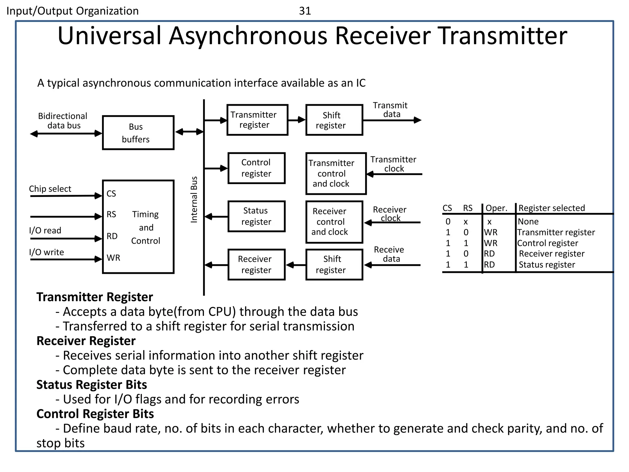
This document discusses input/output organization and peripheral devices. It covers the following key points in 3 sentences:
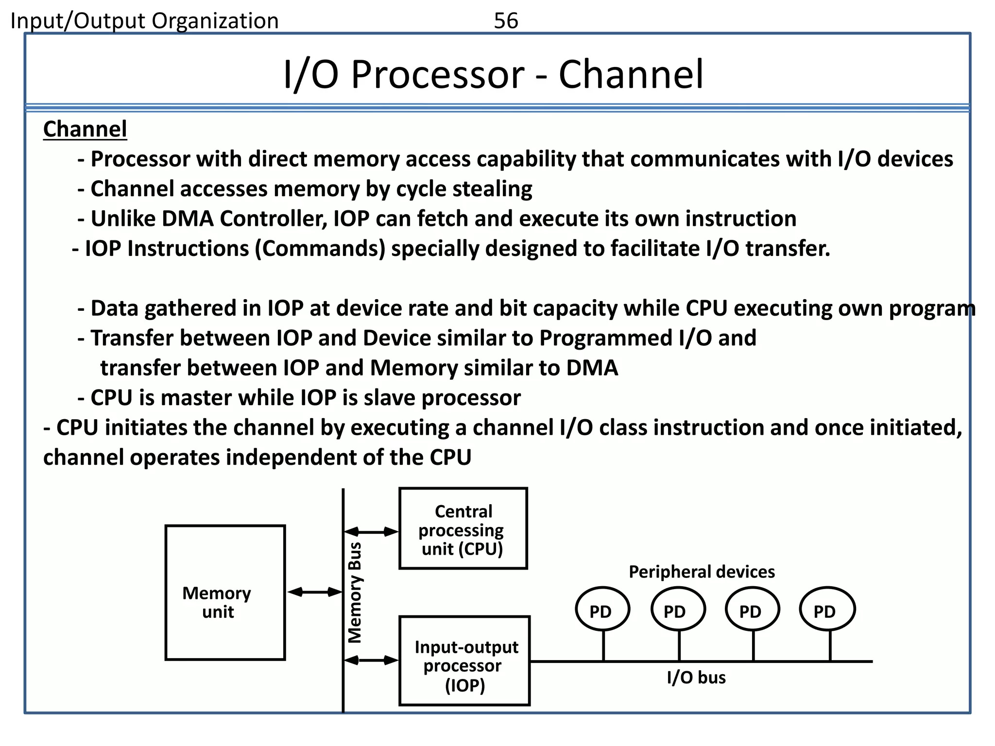
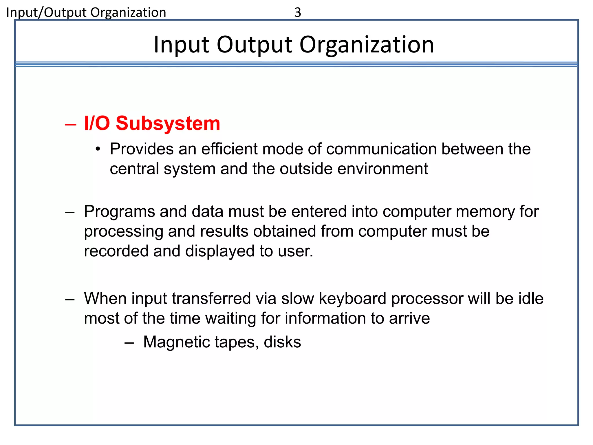
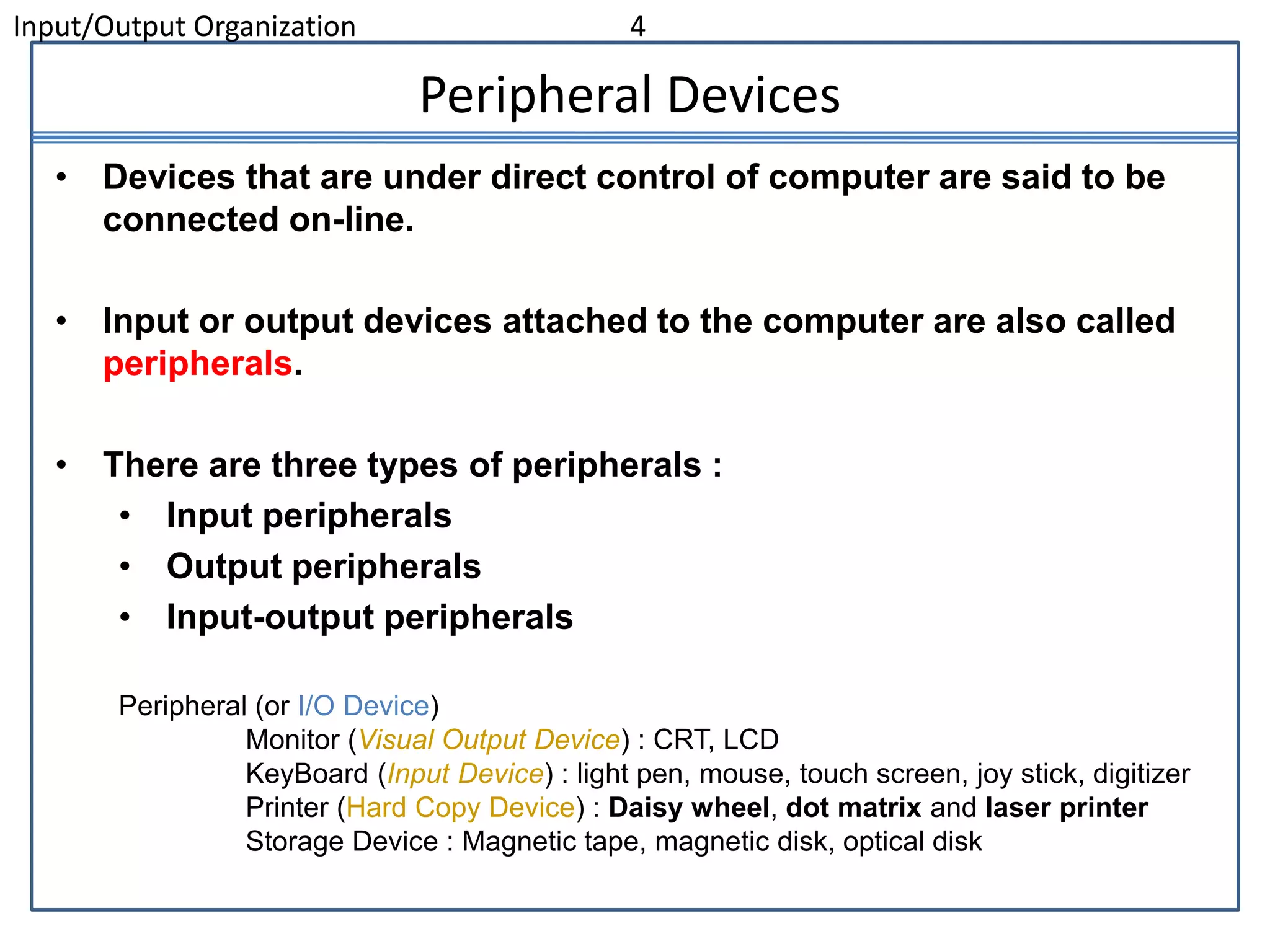
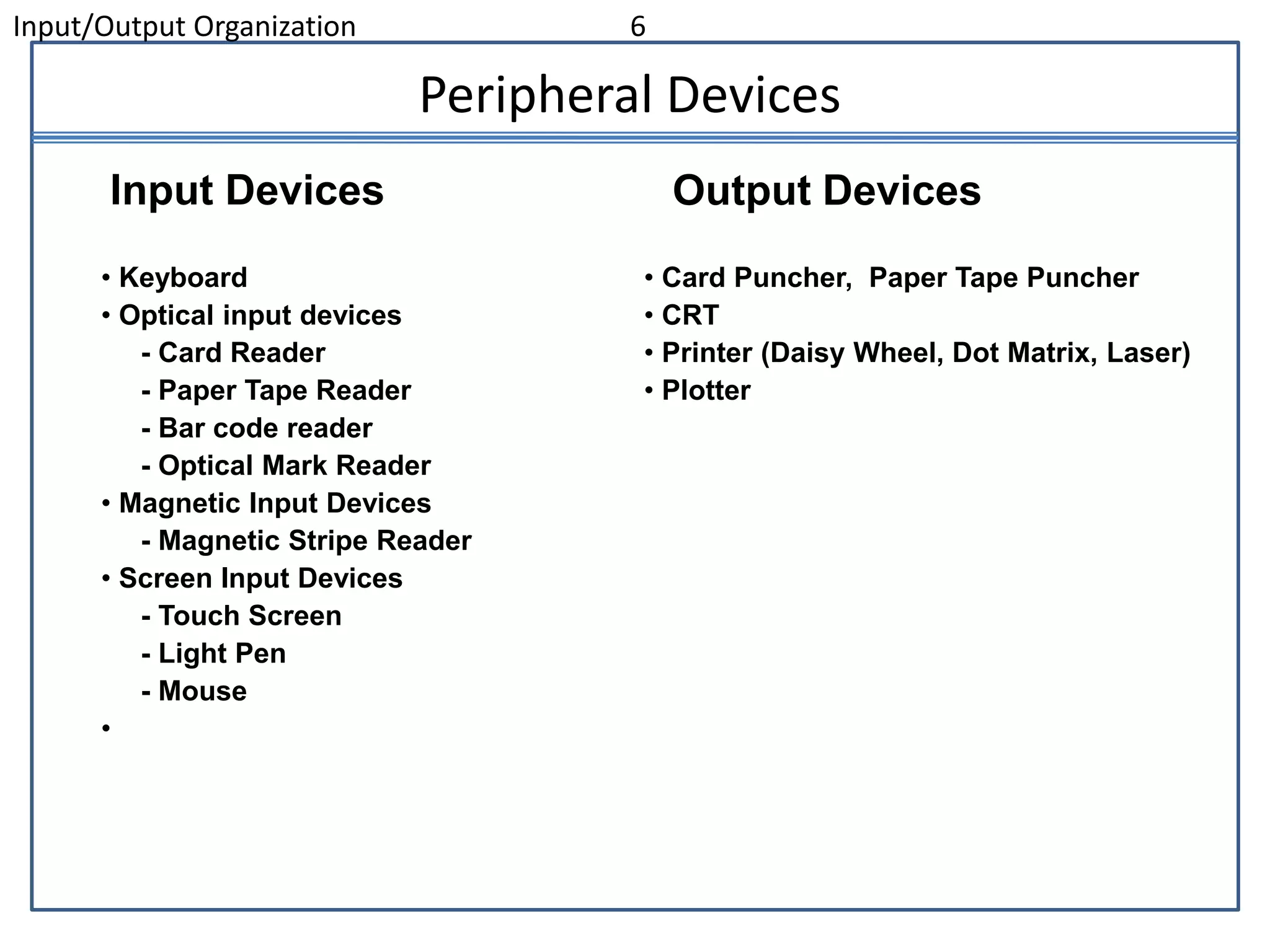
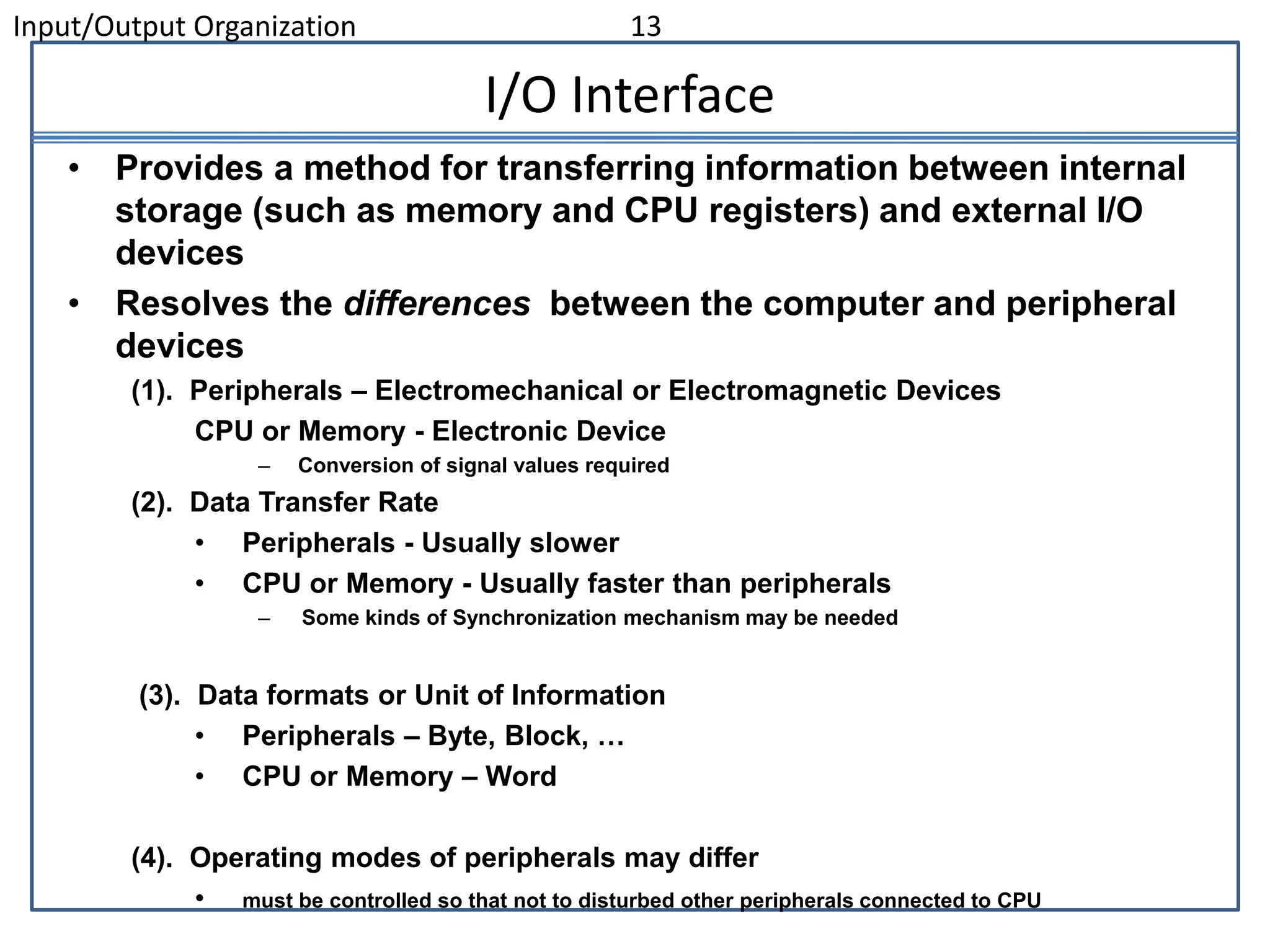
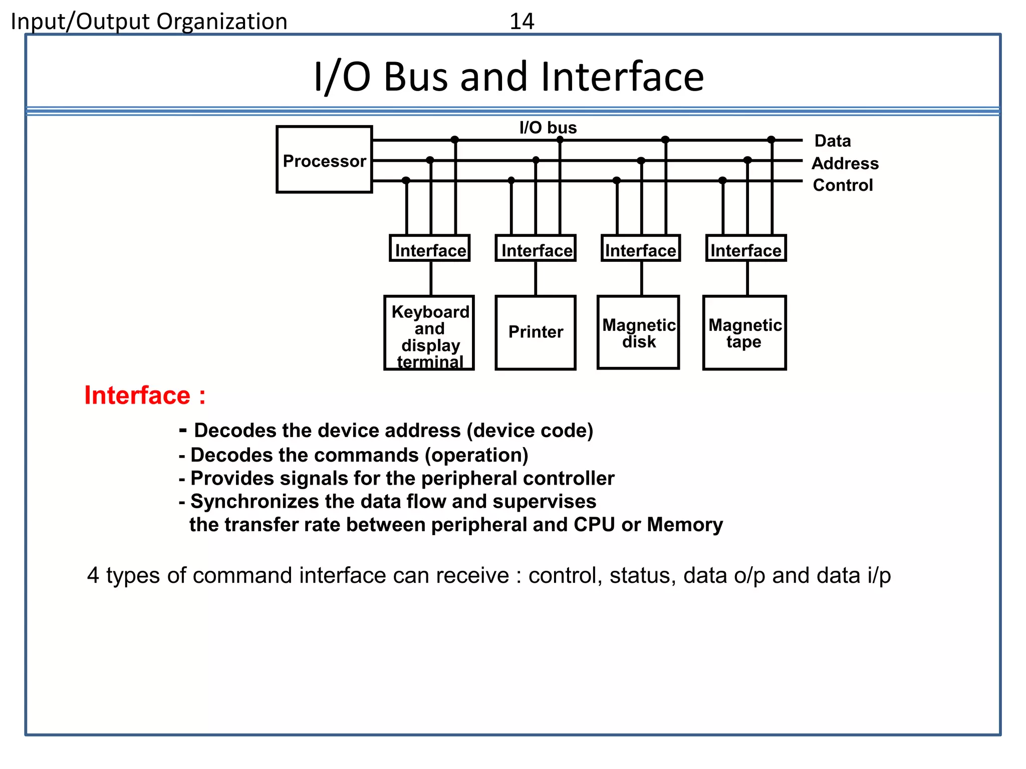
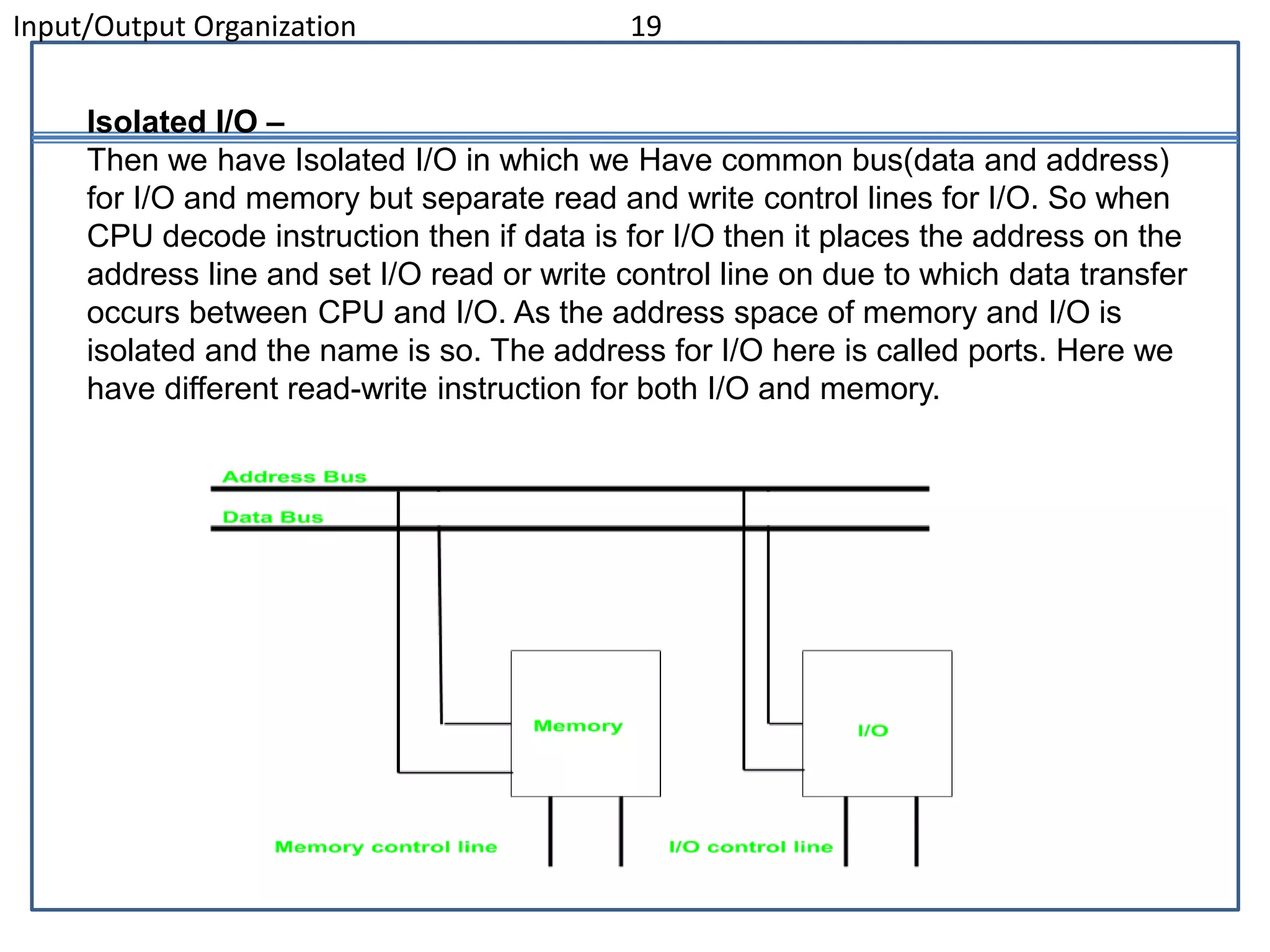
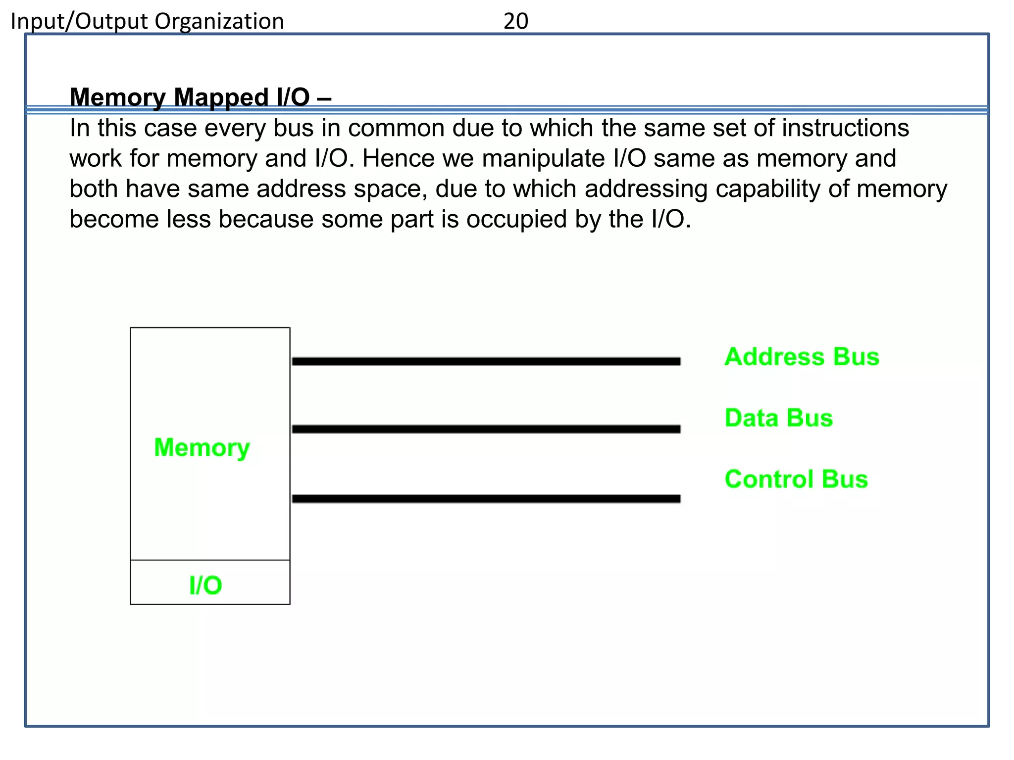
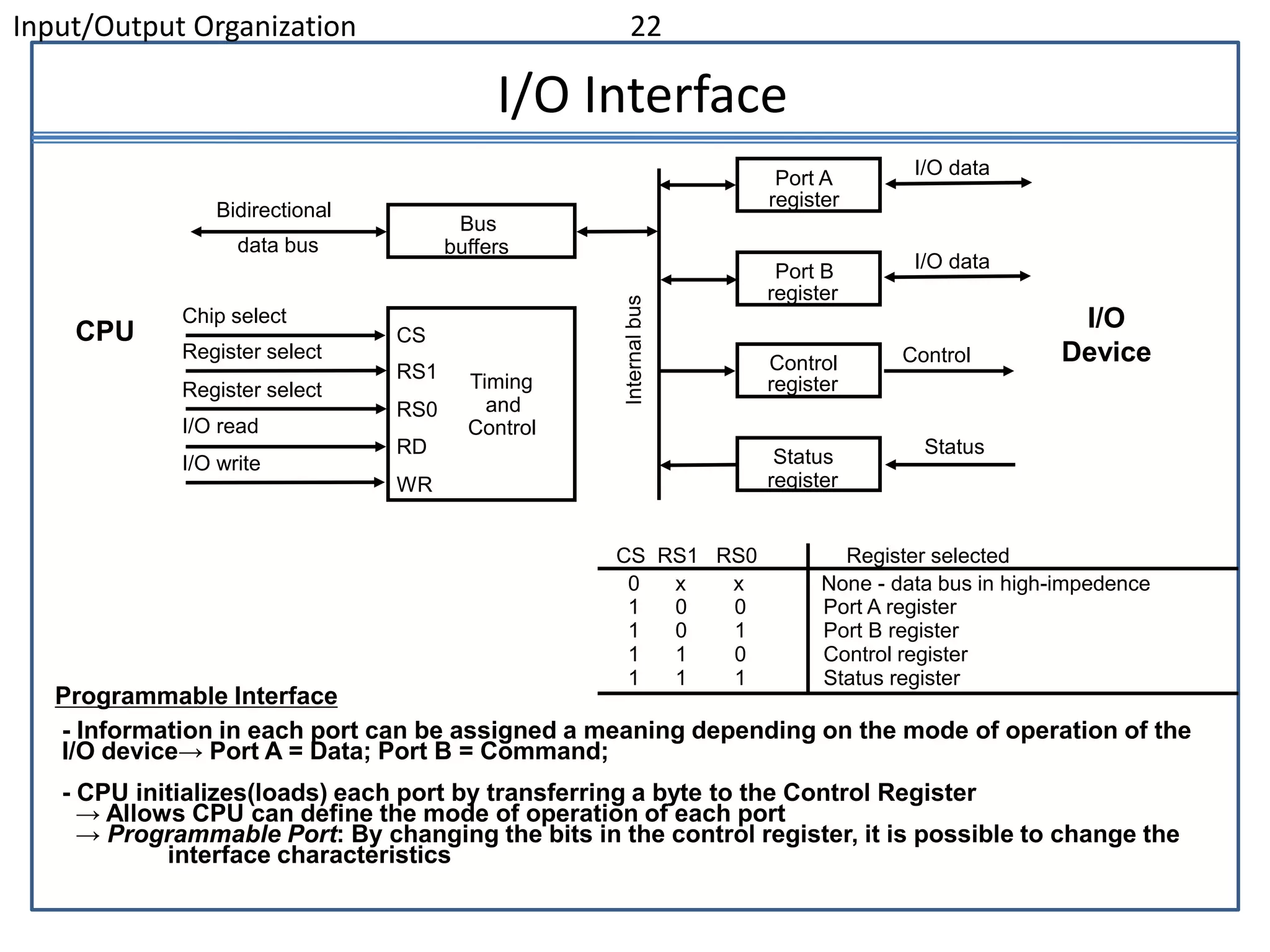
Peripheral devices allow input and output between the computer and external environment. The document outlines different types of input devices, output devices, and input/output devices. It also discusses the input/output interface which provides communication between the CPU, memory, and peripheral devices by resolving differences in data formats, transfer rates, and operating modes.
The document discusses input/output organization. It covers peripheral devices, input-output interfaces, asynchronous data transfer, modes of transfer including programmed I/O, interrupt-initiated I/O, and direct memory access (DMA), priority interrupts, and input-output processors. Specifically, it describes how priority interrupts work using both software polling and hardware daisy chaining approaches, and how parallel priority interrupts use an interrupt register, mask register, and priority encoder to determine the highest priority interrupt request.
The document discusses various topics related to input/output organization in a computer system. It describes peripheral devices that interface with the computer and transfer data asynchronously. It discusses different methods of asynchronous data transfer including strobe pulse and handshaking. It also covers topics like interrupt priority, direct memory access (DMA), input/output processors, and serial communication.
The document discusses various topics related to input/output organization in a computer system. It describes peripheral devices that interface with the computer and transfer data asynchronously. It discusses different methods of asynchronous data transfer including strobe pulse and handshaking. It also covers topics like UART, FIFO buffers, and different modes of data transfer between CPU and peripheral devices including program-controlled, interrupt-initiated, and direct memory access.
The document discusses various topics related to input/output organization in a computer system. It describes peripheral devices that interface with the computer and transfer data asynchronously. It discusses the input/output interface that provides communication between the CPU and I/O devices. It also describes asynchronous data transfer methods like strobe pulse and handshaking that allow synchronization between independent units transferring data asynchronously.
A peripheral device provides input/output functions for a computer as an auxiliary device without core computing functionality. Peripheral devices are classified into input devices, output devices, and storage devices. An input/output interface helps transfer information between internal storage and external peripheral devices. It resolves differences in data formats and speeds between the CPU and peripheral devices. The interface provides control signals and buffers data to synchronize operations. Computers can use separate I/O and memory buses or a common bus with separate control lines or common control lines to communicate with peripherals and memory.
The document discusses various aspects of input-output organization in computer systems. It describes peripheral devices, input-output interfaces, asynchronous data transfer methods using handshaking, direct memory access, interrupt handling, and input-output processors. The key aspects covered are the interface between the computer and external devices, synchronization for asynchronous data transfer, and different modes of transferring data between memory and I/O devices.
The input-output subsystem allows communication between the central computer system and external devices. Peripherals like keyboards, printers, and storage devices are connected via interface units that resolve differences in data formats and transfer rates. There are two main methods for organizing input-output - isolated I/O uses separate instructions to access interface registers, while memory-mapped I/O accesses peripherals through memory addresses on a shared bus. Asynchronous transfer between asynchronous units like the CPU and I/O interfaces requires control signals to synchronize the transmission of data.
The document discusses input/output organization and accessing I/O devices. There are three key components to a computer system: the processor, memory, and I/O modules. I/O modules interface between peripheral devices and the system bus, controlling the transfer of data. I/O modules perform functions like control and timing, processor/device communication, data buffering, and error detection to facilitate input and output.
The document discusses different methods for accessing I/O devices in computer systems. It describes how I/O devices connect to the processor through ports and can be accessed using IN and OUT instructions. There are three main strategies for I/O - polled I/O, interrupt-driven I/O, and direct memory access (DMA). Polled I/O involves the processor continuously checking devices for readiness, interrupt-driven I/O uses interrupts to signal readiness, and DMA allows direct transfer between device and memory without involving the CPU. The strategies differ in transfer rates, latency, and CPU overhead.
This document discusses input/output organization in computer systems. It describes peripheral devices for input and output, input/output interfaces that allow communication between peripherals and the CPU/memory, and various methods for transferring data asynchronously between independent devices or systems, including strobe control, handshaking, and serial transmission. Asynchronous data transfer is necessary because peripherals often operate at different speeds than the CPU and memory.
This document provides information about input-output interfaces in computer systems. It discusses how interface units connect peripheral devices to the CPU and resolve differences in data formats and transfer rates. Interface units include address decoders, registers for control, status, and transferring data. The document contrasts isolated I/O, where separate input/output instructions are used, versus memory-mapped I/O, where I/O devices use memory addresses. It provides an example of an interface unit with control, status and data registers that communicate with the CPU over a shared bus.
The document discusses input-output organization in computer systems. It describes peripheral devices, input-output interfaces, asynchronous data transfer methods like handshaking, direct memory access, interrupt-driven I/O, and the universal asynchronous receiver-transmitter chip. The input-output system allows communication between the computer and external devices by resolving differences in data rates and operating protocols.
The document discusses various aspects of input and output devices and their interface with the central processing unit of a computer system. It describes how peripherals like keyboards, displays and printers are connected and controlled. It explains the different modes of data transfer between CPU and peripherals, including programmed I/O, interrupt-initiated I/O, and direct memory access. The document also covers topics like asynchronous and synchronous data transmission, handshaking, and hardware priority interrupts.
This document discusses input/output organization in computer systems. It describes:
1) Peripheral devices for input and output and how they connect to the computer via interface modules on an I/O bus.
2) Asynchronous data transfer methods like handshaking that allow communication between devices running at different speeds.
3) Memory-mapped I/O that uses memory addresses for I/O, improving flexibility over isolated I/O that has separate address spaces.
4) Asynchronous serial transfer of data one bit at a time using start and stop bits to delineate characters transferred.
This document provides an overview of input/output organization. It discusses peripheral devices, input and output interfaces, asynchronous data transfer, modes of transfer, interrupts, direct memory access, I/O processors, and serial communication. It describes common input devices like keyboards and optical scanners and output devices like printers and displays. It also covers I/O interfaces, buses, isolated versus memory mapped I/O, and programmable I/O interfaces.
The document discusses input-output organization and describes various input and output peripheral devices. It then covers input-output interfaces, how data is transferred asynchronously between devices and the CPU using handshaking, and different modes of data transfer including program-controlled, interrupt-initiated, and direct memory access. It also discusses how interrupts from multiple devices are handled using priority levels and interrupt vectors.
This document discusses memory and I/O interfacing in microprocessors. It describes the parallel communication interface 8255 which allows a microprocessor to interface with peripheral devices. The 8255 has three 8-bit ports that can be programmed to work in different modes like basic I/O, strobed I/O, and bidirectional modes. It reduces external logic needed for interfacing and can be programmed to perform specific functions through control words. The document also briefly mentions other programmable peripheral devices like serial interface 8251, timer 8254, and interrupt controller 8259.
The document discusses input/output organization in computers. It explains that all input/output devices connect to the computer via a bus that allows exchange of address, data and control signals. Each device is assigned a unique address. When the processor requests a read or write, the requested data is placed on the data lines and the address is sent to the address lines. Commonly used I/O mechanisms include interrupts and direct memory access. Memory mapped I/O allows I/O devices and memory to share the same address space.
The document discusses input/output (I/O) problems in computer systems and solutions to those problems. Some key issues addressed are the variety of peripheral devices with different data rates and formats, and the mismatch between peripheral and processor speeds. The document describes I/O modules that interface between the CPU/memory and peripherals. I/O modules handle control, buffering, error detection and allow different I/O techniques like programmed I/O, interrupt-driven I/O and direct memory access (DMA) to transfer data efficiently.
The document discusses input-output organization between a CPU and peripherals. It notes that signal conversion and synchronization may be required due to differences in data rates and formats. Special interface hardware is used to supervise and synchronize input and output transfers. The document also discusses asynchronous and synchronous data transfer methods and the use of I/O buses versus memory buses for communication with peripherals.
This document discusses different techniques for data transfer between the CPU and I/O devices, including programmed I/O, interrupt-driven I/O, and direct memory access (DMA). It describes the basic functioning of an I/O module, comparing programmed I/O to interrupt-driven I/O. It then provides details on DMA, including how it allows high-speed transfer of data directly between memory and I/O devices without CPU involvement. The document also covers I/O interfaces, asynchronous data transfer methods like handshaking, and serial transmission techniques.
The document discusses input/output (I/O) organization in computers. It describes how the I/O subsystem provides communication between external devices and the central processing system. Common peripheral devices include monitors, keyboards, printers, and magnetic tapes. The document outlines different I/O techniques including programmed I/O, interrupt-driven I/O, and direct memory access. It also discusses I/O interfaces, addressing schemes, and how interrupts work to signal device completion.
The primary purpose of memory interfacing is to facilitate the transfer of da...Sindhu Mani
The document discusses memory interfacing concepts. It begins by outlining key concepts in memory interfacing such as the address bus, data bus, control signals, and memory decoding. It then discusses microprocessor interfacing, specifically I/O addressing using port-based and bus-based approaches. The document also covers interrupts, direct memory access (DMA), and the universal asynchronous receiver/transmitter (UART) component.
The document discusses input/output (I/O) organization in computers. It covers various topics related to I/O including I/O interfaces, asynchronous and synchronous data transfer, and different modes of data transfer like programmed I/O and direct memory access. It describes how I/O devices connect to the computer and how interface modules resolve differences in data formats and transfer rates between I/O devices and the CPU. It also discusses I/O buses and different methods of communication between CPU, memory, and I/O including separate I/O and memory buses, isolated I/O using separate control lines, and memory mapped I/O.
A SYSTEMATIC RISK ASSESSMENT APPROACH FOR SECURING THE SMART IRRIGATION SYSTEMSIJNSA Journal
The smart irrigation system represents an innovative approach to optimize water usage in agricultural and landscaping practices. The integration of cutting-edge technologies, including sensors, actuators, and data analysis, empowers this system to provide accurate monitoring and control of irrigation processes by leveraging real-time environmental conditions. The main objective of a smart irrigation system is to optimize water efficiency, minimize expenses, and foster the adoption of sustainable water management methods. This paper conducts a systematic risk assessment by exploring the key components/assets and their functionalities in the smart irrigation system. The crucial role of sensors in gathering data on soil moisture, weather patterns, and plant well-being is emphasized in this system. These sensors enable intelligent decision-making in irrigation scheduling and water distribution, leading to enhanced water efficiency and sustainable water management practices. Actuators enable automated control of irrigation devices, ensuring precise and targeted water delivery to plants. Additionally, the paper addresses the potential threat and vulnerabilities associated with smart irrigation systems. It discusses limitations of the system, such as power constraints and computational capabilities, and calculates the potential security risks. The paper suggests possible risk treatment methods for effective secure system operation. In conclusion, the paper emphasizes the significant benefits of implementing smart irrigation systems, including improved water conservation, increased crop yield, and reduced environmental impact. Additionally, based on the security analysis conducted, the paper recommends the implementation of countermeasures and security approaches to address vulnerabilities and ensure the integrity and reliability of the system. By incorporating these measures, smart irrigation technology can revolutionize water management practices in agriculture, promoting sustainability, resource efficiency, and safeguarding against potential security threats.
DEEP LEARNING FOR SMART GRID INTRUSION DETECTION: A HYBRID CNN-LSTM-BASED MODELgerogepatton
As digital technology becomes more deeply embedded in power systems, protecting the communication
networks of Smart Grids (SG) has emerged as a critical concern. Distributed Network Protocol 3 (DNP3)
represents a multi-tiered application layer protocol extensively utilized in Supervisory Control and Data
Acquisition (SCADA)-based smart grids to facilitate real-time data gathering and control functionalities.
Robust Intrusion Detection Systems (IDS) are necessary for early threat detection and mitigation because
of the interconnection of these networks, which makes them vulnerable to a variety of cyberattacks. To
solve this issue, this paper develops a hybrid Deep Learning (DL) model specifically designed for intrusion
detection in smart grids. The proposed approach is a combination of the Convolutional Neural Network
(CNN) and the Long-Short-Term Memory algorithms (LSTM). We employed a recent intrusion detection
dataset (DNP3), which focuses on unauthorized commands and Denial of Service (DoS) cyberattacks, to
train and test our model. The results of our experiments show that our CNN-LSTM method is much better
at finding smart grid intrusions than other deep learning algorithms used for classification. In addition,
our proposed approach improves accuracy, precision, recall, and F1 score, achieving a high detection
accuracy rate of 99.50%.
KuberTENes Birthday Bash Guadalajara - K8sGPT first impressionsVictor Morales
K8sGPT is a tool that analyzes and diagnoses Kubernetes clusters. This presentation was used to share the requirements and dependencies to deploy K8sGPT in a local environment.
Using recycled concrete aggregates (RCA) for pavements is crucial to achieving sustainability. Implementing RCA for new pavement can minimize carbon footprint, conserve natural resources, reduce harmful emissions, and lower life cycle costs. Compared to natural aggregate (NA), RCA pavement has fewer comprehensive studies and sustainability assessments.
International Conference on NLP, Artificial Intelligence, Machine Learning an...gerogepatton
International Conference on NLP, Artificial Intelligence, Machine Learning and Applications (NLAIM 2024) offers a premier global platform for exchanging insights and findings in the theory, methodology, and applications of NLP, Artificial Intelligence, Machine Learning, and their applications. The conference seeks substantial contributions across all key domains of NLP, Artificial Intelligence, Machine Learning, and their practical applications, aiming to foster both theoretical advancements and real-world implementations. With a focus on facilitating collaboration between researchers and practitioners from academia and industry, the conference serves as a nexus for sharing the latest developments in the field.
Harnessing WebAssembly for Real-time Stateless Streaming PipelinesChristina Lin
Traditionally, dealing with real-time data pipelines has involved significant overhead, even for straightforward tasks like data transformation or masking. However, in this talk, we’ll venture into the dynamic realm of WebAssembly (WASM) and discover how it can revolutionize the creation of stateless streaming pipelines within a Kafka (Redpanda) broker. These pipelines are adept at managing low-latency, high-data-volume scenarios.
ACEP Magazine edition 4th launched on 05.06.2024Rahul
This document provides information about the third edition of the magazine "Sthapatya" published by the Association of Civil Engineers (Practicing) Aurangabad. It includes messages from current and past presidents of ACEP, memories and photos from past ACEP events, information on life time achievement awards given by ACEP, and a technical article on concrete maintenance, repairs and strengthening. The document highlights activities of ACEP and provides a technical educational article for members.
Literature Review Basics and Understanding Reference Management.pptxDr Ramhari Poudyal
Three-day training on academic research focuses on analytical tools at United Technical College, supported by the University Grant Commission, Nepal. 24-26 May 2024
We have compiled the most important slides from each speaker's presentation. This year’s compilation, available for free, captures the key insights and contributions shared during the DfMAy 2024 conference.
IEEE Aerospace and Electronic Systems Society as a Graduate Student Member
Unit4_IO_13623_AnilRawat.ppt
1. Input/Output Organization 1
Overview
Peripheral Devices
Input-Output Interface
Asynchronous Data Transfer
Modes of Transfer
Priority Interrupt
Direct Memory Access
Input-Output Processor
Serial Communication
2. POLL 1
• Which of the following is a Peripheral device
A) All input devices
B) All output devices
C) Both A and B
D) None of the above
3. Input/Output Organization 3
Input Output Organization
– I/O Subsystem
• Provides an efficient mode of communication between the
central system and the outside environment
– Programs and data must be entered into computer memory for
processing and results obtained from computer must be
recorded and displayed to user.
– When input transferred via slow keyboard processor will be idle
most of the time waiting for information to arrive
– Magnetic tapes, disks
4. Input/Output Organization 4
Peripheral Devices
• Devices that are under direct control of computer are said to be
connected on-line.
• Input or output devices attached to the computer are also called
peripherals.
• There are three types of peripherals :
• Input peripherals
• Output peripherals
• Input-output peripherals
Peripheral (or I/O Device)
Monitor (Visual Output Device) : CRT, LCD
KeyBoard (Input Device) : light pen, mouse, touch screen, joy stick, digitizer
Printer (Hard Copy Device) : Daisy wheel, dot matrix and laser printer
Storage Device : Magnetic tape, magnetic disk, optical disk
5. Poll 2
• Which of the following is a Peripheral device
• A) Touch screen
• B) CRT
• C) LCD
• D) All of the above
7. POLL 3
• Card puncher is a
• A) Input device
• B) Output device
• C) both A and B
• D) none of the above
8. Input/Output Organization 8
Input Output Organization
ASCII (American Standard Code for Information Interchange)
• I/O communications usually involves transfer of alphanumeric
information from the device and the computer.
• Standard binary code for alphanumeric character is ASCII
• ASCII Code :
• It uses 7 bits to code 128 characters (94 printable and 34 non printing)
• 7 bit - 00 - 7F ( 0 - 127 )
• ASCII is 7 bits but most computers manipulate 8 bit quantity as a
single unit called byte.
80 - FF ( 128 - 255 ) : Greek, Italic type font
•Three types of control characters: Format effectors, Information
separators and communication control
9. Poll 4
• ASCII Stands for
• A) American Standard Code for Information
Interchange
• B) American Stable Code for Information
Interchange
• C) American Standard Communication for
Information Interchange
• American Standard Code for Information
Interlink
10.
11. • Format Effectors: control the layout of
printing. They include familiar typewriter
controls, such as backspace (BS), horizontal
tabulation(HT), carriage return(CR).
• Information separators: used to separate data
into divisions like paragraphs and pages. They
include characters such as record separator
(RS) and file separator(FS).
12. • Communication Control characters: these are
useful during the transmission of text
between remote terminals. These include
STX(Start of text) and ETX(end of text)
13. Input/Output Organization 13
I/O Interface
• Provides a method for transferring information between internal
storage (such as memory and CPU registers) and external I/O
devices
• Resolves the differences between the computer and peripheral
devices
(1). Peripherals – Electromechanical or Electromagnetic Devices
CPU or Memory - Electronic Device
– Conversion of signal values required
(2). Data Transfer Rate
• Peripherals - Usually slower
• CPU or Memory - Usually faster than peripherals
– Some kinds of Synchronization mechanism may be needed
(3). Data formats or Unit of Information
• Peripherals – Byte, Block, …
• CPU or Memory – Word
(4). Operating modes of peripherals may differ
• must be controlled so that not to disturbed other peripherals connected to CPU
14. Input/Output Organization 14
I/O Bus and Interface
Interface :
- Decodes the device address (device code)
- Decodes the commands (operation)
- Provides signals for the peripheral controller
- Synchronizes the data flow and supervises
the transfer rate between peripheral and CPU or Memory
Processor
Interface
Keyboard
and
display
terminal
Magnetic
tape
Printer
Interface Interface Interface
Data
Address
Control
Magnetic
disk
I/O bus
4 types of command interface can receive : control, status, data o/p and data i/p
15. POLL
• Which of the following is Correct about I/O
interface
• A) Device address
• B) peripheral controller
• C) both A and B
• D none of the above
16. Input/Output Organization 16
I/O Bus and Interface
•Control command : is issued to activate peripheral and to inform what to do
•Status command : used to test various status condition in the interface and
the peripherals
•data o/p command : causes the interface to respond by transferring data from
the bus into one of its registers
•data i/p command : interface receives an item of data from the peripheral and
places it in its buffer register.
17. POLL
• Which of the following is a example of I/O
command
• A) Control
• B) Status
• C) Data
• D) All of the above
18. Input/Output Organization 18
I/O Bus and Memory Bus
• MEMORY BUS is for information transfers between CPU and the MM
• I/O BUS is for information transfers between CPUand I/O devices through
their I/O interface
•3 ways to bus can communicate with memory and I/O :
(1). use two separate buses, one to communicate with memory and the
other with I/O interfaces
- Computer has independent set of data, address and control bus one for
accessing memory and another I/O.
- done in computers that have separate IOP other than CPU.
(2). Use one common bus for memory and I/O but separate control lines
for each
(3). Use one common bus for memory and I/O with common control
lines for both
Functions of Buses
19. Input/Output Organization 19
Isolated I/O –
Then we have Isolated I/O in which we Have common bus(data and address)
for I/O and memory but separate read and write control lines for I/O. So when
CPU decode instruction then if data is for I/O then it places the address on the
address line and set I/O read or write control line on due to which data transfer
occurs between CPU and I/O. As the address space of memory and I/O is
isolated and the name is so. The address for I/O here is called ports. Here we
have different read-write instruction for both I/O and memory.
20. Input/Output Organization 20
Memory Mapped I/O –
In this case every bus in common due to which the same set of instructions
work for memory and I/O. Hence we manipulate I/O same as memory and
both have same address space, due to which addressing capability of memory
become less because some part is occupied by the I/O.
21. Isolated I/O Memory Mapped I/O
Memory and I/O have seperate
address space
Both have same address space
All address can be used by the
memory
Due to addition of I/O addressable
memory become less for memory
Separate instruction control read and
write operation in I/O and Memory
Same instructions can control both I/O
and Memory
In this I/O address are called ports. Normal memory address are for both
More efficient due to seperate buses Lesser efficient
Larger in size due to more buses Smaller in size
It is complex due to separate separate
logic is used to control both.
Simpler logic is used as I/O is also
treated as memory only.
Differences between memory mapped I/O and isolated I/O –
22. Input/Output Organization 22
I/O Interface
- Information in each port can be assigned a meaning depending on the mode of operation of the
I/O device→ Port A = Data; Port B = Command;
- CPU initializes(loads) each port by transferring a byte to the Control Register
→ Allows CPU can define the mode of operation of each port
→ Programmable Port: By changing the bits in the control register, it is possible to change the
interface characteristics
CS RS1 RS0 Register selected
0 x x None - data bus in high-impedence
1 0 0 Port A register
1 0 1 Port B register
1 1 0 Control register
1 1 1 Status register
Programmable Interface
Chip select
Register select
Register select
I/O read
I/O write
CS
RS1
RS0
RD
WR
Timing
and
Control
Bus
buffers
Bidirectional
data bus
Port A
register
Port B
register
Control
register
Status
register
I/O data
I/O data
Control
Status
CPU I/O
Device
23. 11-3. Asynchronous Data Transfer
Synchronous Data Transfer: Clock pulses are applied to all registers
within a unit and all data transfer among internal registers occur
simultaneously during the occurrence of a clock pulse.
Two units such as CPU and I/O Interface are designed independently of
each other.
If the registers in the interface share a common clock with CPU
registers, the transfer between the two is said to be synchronous.
24. 11-3. Asynchronous Data Transfer
Asynchronous Data Transfer: Internal timing in each unit (CPU and
Interface) is independent.
Each unit uses its own private clock for internal registers. Asynchronous
data transfer between two independent units requires that control
signals be transmitted between the communicating units to indicate
the time at which data is being transmitted.
One way of achieving this is by means of STROBE(Control signal to
indicate the time at which data is being transmitted) pulse
and other method is HANDSHAKING(Agreement between two
independent units).
28. Timeout : If the return handshake signal does not respond within a given time period,
the unit assumes that an error has occurred.
29. – Asynchronous Serial Transfer
• Synchronous transmission :
– The two unit share a common clock frequency
– Bits are transmitted continuously at the rate dictated by the clock
pulses
• Asynchronous transmission :
– Binary information sent only when it is available and line remain
idle otherwise
– Special bits are inserted at both ends of the character code
– Each character consists of three parts :
» 1) start bit : always “0”, indicate the beginning of a character
» 2) character bits : data
» 3) stop bit : always “1”
1 1 1
1 0
0
0
0
Start
bit
Character bits
Stop
bit
30. • Asynchronous transmission rules :
– When a character is not being sent, the line is kept in the 1-state
– The initiation of a character transmission is detected from the
start bit, which is always “0”
– The character bits always follow the start bit
– After the last bit of the character is transmitted, a stop bit is
detected when the line returns to the 1-state for at least one bit
time
• Baud Rate : Data transfer rate in bits per second
– 10 character per second with 11 bit format = 110 bit per second
31. Input/Output Organization 31
Universal Asynchronous Receiver Transmitter
A typical asynchronous communication interface available as an IC
Transmitter Register
- Accepts a data byte(from CPU) through the data bus
- Transferred to a shift register for serial transmission
Receiver Register
- Receives serial information into another shift register
- Complete data byte is sent to the receiver register
Status Register Bits
- Used for I/O flags and for recording errors
Control Register Bits
- Define baud rate, no. of bits in each character, whether to generate and check parity, and no. of
stop bits
Chip select
I/O read
I/O write
CS
RS
RD
WR
Timing
and
Control
Bus
buffers
Bidirectional
data bus
Transmitter
register
Control
register
Status
register
Receiver
register
Shift
register
Transmitter
control
and clock
Receiver
control
and clock
Shift
register
Transmit
data
Transmitter
clock
Receiver
clock
Receive
data
CS RS Oper. Register selected
0 x x None
1 0 WR Transmitter register
1 1 WR Control register
1 0 RD Receiver register
1 1 RD Status register
Internal
Bus
32. Binary information received from external device is usually
stored in memory.
Information transferred from central computer into an external
device originates in the memory unit.
The CPU merely execute I/O instructions and may accept data
temporarily but ultimate source or destination is the Memory Unit.
Data transfer between central computer and I/O devices may be
handled in a variety of modes. Some modes use CPU as
intermediate path and others transfer data directly to and from
memory unit.
Data Transfer to or from peripheral can be handled in one of
three possible modes :
Programmed I/O
Interrupt-Initiated I/O
Direct Memory Access (DMA)
Modes of Transfer
35. Programmed I/O
- Programmed I/O operations are the result of I/O
Instructions written in computer program.
Each data item transfer is initiated by an instruction in
the program.
- Usually, transfer is to and from a CPU register to
peripheral.
- Other instructions are needed to transfer data to and from CPU
and Memory
- Transferring data under program control requires
constant monitoring of the peripheral by CPU.
36. • In programmed I/O method, CPU stays in a
program loop until the I/O unit indicated that it is
ready for data transfer.
• This is a time consuming process since it keeps
the processor busy needlessly.
• It can be avoided by using Interrupt facility and
special commands to inform the interface to issue
an interrupt request signal when data are
available for the device.
39. Priority Interrupts
Priority
- Determines which interrupt is to be served first when two or more requests
are made simultaneously
- Also determines which interrupts are permitted to interrupt the computer while
another is being serviced
- Higher priority interrupts can make requests while servicing a lower priority
interrupt
A priority interrupt is a system that establishes priority over the
various sources to determine
- which condition is to serviced first when two or more requests
arrive simultaneously
-which conditions are permitted to interrupt the computer while
another request is being serviced
40. Priority Interrupts
Priority Interrupt by Software (Polling)
Polling procedure is used to identify highest priority source by software
means
- common branch address for all the interrupts
- Priority is established by the order of polling the devices(interrupt sources)
- highest priority device is tested first and if interrupt is on , control
branches to service routine for this source otherwise next lower priority
source is tested
- Flexible since it is established by software
- Low cost since it needs a very little hardware
- Very slow
- if there are many interrupt time required to poll may exceed time available to
service IO device
41. Priority Interrupts
Priority Interrupt by Hardware
- Require a priority interrupt manager which accepts all the interrupt requests
to determine the highest priority request
- Fast since identification of the highest priority interrupt request is identified by
the hardware
- Fast since each interrupt source has its own interrupt vector to access
directly to its own service routine
- Can be addressed using serial or parallel connection of interrupt lines.
Example of serial is Daisy chaining Priority
42. Hardware Priority Interrupts – Daisy Chain
Device 1
PI PO
Device 2
PI PO
Device 3
PI PO
INT
INTACK
Interrupt request
Interrupt acknowledge
To next
device
CPU
VAD 1 VAD 2 VAD 3
* Serial hardware priority function
* Interrupt Request Line
- Single common line
* Interrupt Acknowledge Line
- Daisy-Chain
-Serial connection of all device that request an interrupt
-Device with highest priority placed in first position followed by devices with lower
priority and so on.
-Interrupt generated by any device signals low state interrupt line
-CPU responds by enabling interrupt acknowledgement (INTACK) line.
- device receives PI=1 and passes to next only when not requesting else PI=0
-Thus device with PI=1 and PO=0 is one with highest priority requesting interrupt
45. POLL
If PI=1 and PO =0 , then
(a) Interrupt is activated
(b)No Interrupt
(c) Interrupt ACK passed to next device
(d)Invalid Interrupt
46. Parallel Priority Interrupts
Mask
register
INTACK
from CPU
Priority
encoder
I0
I1
I 2
I 3
0
1
2
3
y
x
IST
IEN
0
1
2
3
0
0
0
0
0
0
Disk
Printer
Reader
Keyboard
Interrupt register
Enable
Interrupt
to CPU
VAD
to CPU
Bus
Buffer
IEN: Set or Clear by instructions ION or IOF
IST: Represents an unmasked interrupt has occurred. INTACK enables tristate Bus Buffer to load VAD generated
by the Priority Logic
Interrupt Register:
- Each bit is associated with an Interrupt Request from different Interrupt Source - different priority level
- Each bit can be cleared by a program instruction
Mask Register:
- Mask Register is associated with Interrupt Register
- Each bit can be set or cleared by an Instruction
47. Priority Encoder
Determines the highest priority interrupt when more than one
interrupts take place
Priority Encoder Truth table
1 d d d
0 1 d d
0 0 1 d
0 0 0 1
0 0 0 0
I0 I1 I2 I3
0 0 1
0 1 1
1 0 1
1 1 1
d d 0
x y IST
(IST) = I0 + I1 + I2 + I3
Inputs Outputs
Boolean functions
48. POLL
Which of the following statement is correct
– Parallel Priority interrupt can handle multiple
interrupt request
a. True
b. False
49. Interrupt Cycle
At the end of each Instruction cycle
- CPU checks IEN and IST
- If IEN IST = 1, CPU -> Interrupt Cycle
SP SP - 1 Decrement stack pointer
M[SP] PC Push PC into stack
INTACK 1 Enable interrupt acknowledge
PC VAD Transfer vector address to PC
IEN 0 Disable further interrupts
Go To Fetch to execute the first instruction
in the interrupt service routine
50. Initial and Final Operations
JMP PTR
JMP RDR
JMP KBD
JMP DISK
0
1
2
3
Program to service
magnetic disk
Program to service
line printer
Program to service
character reader
Program to service
keyboard
DISK
PTR
RDR
KBD
255
256
750
256
750
Stack
Main program
current instr.
749
KBD
interrupt
2
VAD=00000011 3
4
Disk
interrupt
5
6
7
8
9 10
11
1
Initial and Final Operations
Each interrupt service routine must have an initial and final set of
operations for controlling the registers in the hardware interrupt system
Initial Sequence
[1] Clear lower level Mask reg. bits
[2] IST <- 0
[3] Save contents of CPU registers
[4] IEN <- 1
[5] Go to Interrupt Service Routine
Final Sequence
[1] IEN <- 0
[2] Restore CPU registers
[3] Clear the bit in the Interrupt Reg
[4] Set lower level Mask reg. bits
[5] Restore return address, IEN <- 1
51. Input/Output Organization 51
Direct Memory Access
Data bus
Read
Write
ABUS
DBUS
RD
WR
Bus request
Bus granted
BR
BG
CPU
Data bus
DMA select
Read
Write
Bus request
Bus grant
Interrupt
DS
RS
RD
WR
BR
BG
Interrupt
Data bus
buffers
Address bus
buffers
Address register
Word count register
Control register
DMA request
DMA acknowledge to I/O device
Control
logic
Internal
Bus
Fig 2: Block diagram of DMA controller
* Block of data transfer between high speed devices like Disk and Memory
* DMA controller - Interface which takes over the buses to manage the transfer directly between
Memory and I/O Device, freeing CPU for other tasks
* CPU initializes DMA Controller by sending memory address and the block size (number of words)
Fig 1: CPU bus signals for DMA transfer
Address bus
Address register:
Contains an address to specify
Desired location in memory
Word count register
Holds no. of words to be transferred
Control register
Specifies the mode of transfer
52. Input/Output Organization 52
DMA Transfer can be made in several ways
(1) Burst Transfer : a block sequence consisting of memory words is transferred
in continuous burst while the DMA controller is master of memory
bus
- This mode of transfer is needed for fast devices such as magnetic
disk where data transmission cannot be stopped or slowed down
until an entire block is transferred
(2) Cycle stealing : Alternative technique called cycle stealing allows DMA controller to
transfer one data word at time after which it must return control of
the buses to the CPU.
- CPU merely delays its operation for one memory cycle to allow the
direct memory I/O transfer to “steal” one memory cycle
Direct Memory Access
RD and WR is bidirectional
When BG=0 CPU can communicate with DMA Register
When BG=1 CPU left the buses and DMA can communicate directly with memory
53. Input/Output Organization 53
DMA I/O Operation
DMA is first initialized by CPU. After that DMA starts and continues to transfer data
between memory and peripheral unit until an entire block is transferred.
CPU initializes the DMA by sending following information through data bus:
(1) Starting address of the memory block (for read/write)
(2) Word Count (no. of words in memory block)
(3) Control to specify mode of transfer (E.g. read/write)
(4) A control to start DMA Transfer
54. Input/Output Organization 55
DMA Transfer
BG
BR
CPU
RD WR Addr Data
Interrupt
Random-access
memory unit (RAM)
RD WR Addr Data
BR
BG
RD WR Addr Data
Interrupt
DS
RS DMA
Controller
I/O
Peripheral
device
DMA request
DMA ack.
Read control
Write control
Data bus
Address bus
Address
select
55. Input/Output Organization 56
I/O Processor - Channel
Channel
- Processor with direct memory access capability that communicates with I/O devices
- Channel accesses memory by cycle stealing
- Unlike DMA Controller, IOP can fetch and execute its own instruction
- IOP Instructions (Commands) specially designed to facilitate I/O transfer.
- Data gathered in IOP at device rate and bit capacity while CPU executing own program
- Transfer between IOP and Device similar to Programmed I/O and
transfer between IOP and Memory similar to DMA
- CPU is master while IOP is slave processor
- CPU initiates the channel by executing a channel I/O class instruction and once initiated,
channel operates independent of the CPU
PD PD PD PD
Peripheral devices
I/O bus
Input-output
processor
(IOP)
Central
processing
unit (CPU)
Memory
unit
Memory
Bus
56. Input/Output Organization 57
Channel CPU Communication
Send instruction
to test IOP.path
If status OK, then send
start I/O instruction
to IOP.
CPU continues with
another program
Transfer status word
to memory
Access memory
for IOP program
Conduct I/O transfers
using DMA;
Prepare status report.
I/O transfer completed;
Interrupt CPU
Request IOP status
Transfer status word
to memory location
Check status word
for correct transfer.
Continue
CPU operations IOP operations