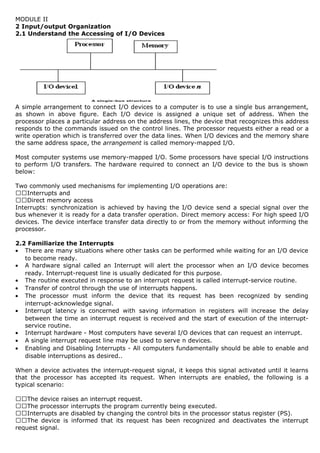
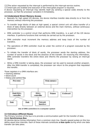
This document provides information on input/output organization and interfaces in a computer system. It discusses different I/O techniques like interrupts and direct memory access. Interrupts allow I/O devices to signal the processor when they need attention. Direct memory access enables high-speed transfer of data directly between I/O devices and memory without processor involvement. The document also describes common I/O bus standards like PCI, SCSI and USB and how they facilitate communication between devices and the computer.
visit: www.techbed.blogspot.com
I/O Memory Interface
Programmable, Interrupt initiated, DMA, Serial and Parallel Interfaces for data transfer
Detailed study of 8251 USART chip
visit: www.techbed.blogspot.com
I/O Memory Interface
Programmable, Interrupt initiated, DMA, Serial and Parallel Interfaces for data transfer
Detailed study of 8251 USART chip
I/O subsystems: Input/output devices such as Disk, CD,ROM, Printer etc.; Interfacing with IO devices, keyboard and display interfaces; Basic concepts Bus Control, Read Write operations, Programmed IO, Concept of handshaking, Polled and Interrupt driven I/O, DMA data transfer
Congratulations! #You have earned 30 reward points for the first Fonepay transaction. Your balance is 30. Redeem points######################################################### have earned 30 reward points for the first Fonepay transaction. Your balance is 30. Redeem points using Fonepay app onelink.to/tn3ze7Congratulations! You have earned 30 reward points for the first Fonepay transaction. Your balance is 30. Redeem points using Fonepay app onelink.to/tn3ze7Congratulations! You have earned 30 reward points for the first Fonepay transaction. Your balance is 30. Redeem points using Fonepay app onelink.to/tn3ze7Congratulations! You have earned 30 reward points for the first Fonepay transaction. Your balance is 30. Redeem points using Fonepay app onelink.to/tn3ze7Congratulations! You have earned 30 reward points for the first Fonepay transaction. Your balance is 30. Redeem points using Fonepay app onelink.to/tn3ze7Congratulations! You have earned 30 reward points for the first Fonepay transaction. Your balance is 30. Redeem points using Fonepay app onelink.to/tn3ze7Congratulations! You have earned 30 reward points for the first Fonepay transaction. Your balance is 30. Redeem points using Fonepay app onelink.to/tn3ze7Congratulations! You have earned 30 reward points for the first Fonepay transaction. Your balance is 30. Redeem points using Fonepay app onelink.to/tn3ze7Congratulations! You have earned 30 reward points for the first Fonepay transaction. Your balance is 30. Redeem points using Fonepay app onelink.to/tn3ze7Congratulations! You have earned 30 reward points for the first Fonepay transaction. Your balance is 30. Redeem points using Fonepay app onelink.to/tn3ze7Congratulations! You have earned 30 reward points for the first Fonepay transaction. Your balance is 30. Redeem points using Fonepay app onelink.to/tn3ze7Congratulations! You have earned 30 reward points for the first Fonepay transaction. Your balance is 30. Redeem points using Fonepay app onelink.to/tn3ze7Congratulations! You have earned 30 reward points for the first Fonepay transaction. Your balance is 30. Redeem points using Fonepay app onelink.to/tn3ze7Congratulations! You have earned 30 reward points for the first Fonepay transaction. Your balance is 30. Redeem points using Fonepay app №########################################################################################################################################################################################################################№##################################№#################################################################################onelink.to/tn3ze7Congratulations! You have earned 30 reward points for the first Fonepay transaction. Your balance is 30. Redeem points using Fonepay app ######onelink.to/tn3z#####################№№#########################e7Congratulations! You have earned 30 reward points for the first Fonepay transaction. Your balance is 30. Redeem p#################################
gfgbfvc cd dc c fvfvdbbbbbbb gfgbfvc cd dc c fvfvdbbbbbbb gfgbfvc cd dc c fvfvdbbbbbbb gfgbfvc cd dc c fvfvdbbbbbbb gfgbfvc cd dc c fvfvdbbbbbbb gfgbfvc cd dc c fvfvdbbbbbbb gfgbfvc cd dc c fvfvdbbbbbbb
About
Indigenized remote control interface card suitable for MAFI system CCR equipment. Compatible for IDM8000 CCR. Backplane mounted serial and TCP/Ethernet communication module for CCR remote access. IDM 8000 CCR remote control on serial and TCP protocol.
• Remote control: Parallel or serial interface.
• Compatible with MAFI CCR system.
• Compatible with IDM8000 CCR.
• Compatible with Backplane mount serial communication.
• Compatible with commercial and Defence aviation CCR system.
• Remote control system for accessing CCR and allied system over serial or TCP.
• Indigenized local Support/presence in India.
• Easy in configuration using DIP switches.
Technical Specifications
Indigenized remote control interface card suitable for MAFI system CCR equipment. Compatible for IDM8000 CCR. Backplane mounted serial and TCP/Ethernet communication module for CCR remote access. IDM 8000 CCR remote control on serial and TCP protocol.
Key Features
Indigenized remote control interface card suitable for MAFI system CCR equipment. Compatible for IDM8000 CCR. Backplane mounted serial and TCP/Ethernet communication module for CCR remote access. IDM 8000 CCR remote control on serial and TCP protocol.
• Remote control: Parallel or serial interface
• Compatible with MAFI CCR system
• Copatiable with IDM8000 CCR
• Compatible with Backplane mount serial communication.
• Compatible with commercial and Defence aviation CCR system.
• Remote control system for accessing CCR and allied system over serial or TCP.
• Indigenized local Support/presence in India.
Application
• Remote control: Parallel or serial interface.
• Compatible with MAFI CCR system.
• Compatible with IDM8000 CCR.
• Compatible with Backplane mount serial communication.
• Compatible with commercial and Defence aviation CCR system.
• Remote control system for accessing CCR and allied system over serial or TCP.
• Indigenized local Support/presence in India.
• Easy in configuration using DIP switches.
Student information management system project report ii.pdfKamal Acharya
Our project explains about the student management. This project mainly explains the various actions related to student details. This project shows some ease in adding, editing and deleting the student details. It also provides a less time consuming process for viewing, adding, editing and deleting the marks of the students.
Water scarcity is the lack of fresh water resources to meet the standard water demand. There are two type of water scarcity. One is physical. The other is economic water scarcity.
CFD Simulation of By-pass Flow in a HRSG module by R&R Consult.pptxR&R Consult
CFD analysis is incredibly effective at solving mysteries and improving the performance of complex systems!
Here's a great example: At a large natural gas-fired power plant, where they use waste heat to generate steam and energy, they were puzzled that their boiler wasn't producing as much steam as expected.
R&R and Tetra Engineering Group Inc. were asked to solve the issue with reduced steam production.
An inspection had shown that a significant amount of hot flue gas was bypassing the boiler tubes, where the heat was supposed to be transferred.
R&R Consult conducted a CFD analysis, which revealed that 6.3% of the flue gas was bypassing the boiler tubes without transferring heat. The analysis also showed that the flue gas was instead being directed along the sides of the boiler and between the modules that were supposed to capture the heat. This was the cause of the reduced performance.
Based on our results, Tetra Engineering installed covering plates to reduce the bypass flow. This improved the boiler's performance and increased electricity production.
It is always satisfying when we can help solve complex challenges like this. Do your systems also need a check-up or optimization? Give us a call!
Work done in cooperation with James Malloy and David Moelling from Tetra Engineering.
More examples of our work https://www.r-r-consult.dk/en/cases-en/
Overview of the fundamental roles in Hydropower generation and the components involved in wider Electrical Engineering.
This paper presents the design and construction of hydroelectric dams from the hydrologist’s survey of the valley before construction, all aspects and involved disciplines, fluid dynamics, structural engineering, generation and mains frequency regulation to the very transmission of power through the network in the United Kingdom.
Author: Robbie Edward Sayers
Collaborators and co editors: Charlie Sims and Connor Healey.
(C) 2024 Robbie E. Sayers
Hybrid optimization of pumped hydro system and solar- Engr. Abdul-Azeez.pdffxintegritypublishin
Advancements in technology unveil a myriad of electrical and electronic breakthroughs geared towards efficiently harnessing limited resources to meet human energy demands. The optimization of hybrid solar PV panels and pumped hydro energy supply systems plays a pivotal role in utilizing natural resources effectively. This initiative not only benefits humanity but also fosters environmental sustainability. The study investigated the design optimization of these hybrid systems, focusing on understanding solar radiation patterns, identifying geographical influences on solar radiation, formulating a mathematical model for system optimization, and determining the optimal configuration of PV panels and pumped hydro storage. Through a comparative analysis approach and eight weeks of data collection, the study addressed key research questions related to solar radiation patterns and optimal system design. The findings highlighted regions with heightened solar radiation levels, showcasing substantial potential for power generation and emphasizing the system's efficiency. Optimizing system design significantly boosted power generation, promoted renewable energy utilization, and enhanced energy storage capacity. The study underscored the benefits of optimizing hybrid solar PV panels and pumped hydro energy supply systems for sustainable energy usage. Optimizing the design of solar PV panels and pumped hydro energy supply systems as examined across diverse climatic conditions in a developing country, not only enhances power generation but also improves the integration of renewable energy sources and boosts energy storage capacities, particularly beneficial for less economically prosperous regions. Additionally, the study provides valuable insights for advancing energy research in economically viable areas. Recommendations included conducting site-specific assessments, utilizing advanced modeling tools, implementing regular maintenance protocols, and enhancing communication among system components.
Hybrid optimization of pumped hydro system and solar- Engr. Abdul-Azeez.pdf
Ca 2 note mano
1. MODULE II
2 Input/output Organization
2.1 Understand the Accessing of I/O Devices
A simple arrangement to connect I/O devices to a computer is to use a single bus arrangement,
as shown in above figure. Each I/O device is assigned a unique set of address. When the
processor places a particular address on the address lines, the device that recognizes this address
responds to the commands issued on the control lines. The processor requests either a read or a
write operation which is transferred over the data lines. When I/O devices and the memory share
the same address space, the arrangement is called memory-mapped I/O.
Most computer systems use memory-mapped I/O. Some processors have special I/O instructions
to perform I/O transfers. The hardware required to connect an I/O device to the bus is shown
below:
Two commonly used mechanisms for implementing I/O operations are:
Interrupts and
Direct memory access
Interrupts: synchronization is achieved by having the I/O device send a special signal over the
bus whenever it is ready for a data transfer operation. Direct memory access: For high speed I/O
devices. The device interface transfer data directly to or from the memory without informing the
processor.
2.2 Familiarize the Interrupts
• There are many situations where other tasks can be performed while waiting for an I/O device
to become ready.
• A hardware signal called an Interrupt will alert the processor when an I/O device becomes
ready. Interrupt-request line is usually dedicated for this purpose.
• The routine executed in response to an interrupt request is called interrupt-service routine.
• Transfer of control through the use of interrupts happens.
• The processor must inform the device that its request has been recognized by sending
interrupt-acknowledge signal.
• Interrupt latency is concerned with saving information in registers will increase the delay
between the time an interrupt request is received and the start of execution of the interrupt-
service routine.
• Interrupt hardware - Most computers have several I/O devices that can request an interrupt.
• A single interrupt request line may be used to serve n devices.
• Enabling and Disabling Interrupts - All computers fundamentally should be able to enable and
disable interruptions as desired..
When a device activates the interrupt-request signal, it keeps this signal activated until it learns
that the processor has accepted its request. When interrupts are enabled, the following is a
typical scenario:
The device raises an interrupt request.
The processor interrupts the program currently being executed.
Interrupts are disabled by changing the control bits in the processor status register (PS).
The device is informed that its request has been recognized and deactivates the interrupt
request signal.
2. The action requested by the interrupt is performed by the interrupt-service routine.
Interrupts are enabled and execution of the interrupted program is resumed.
A device requesting an interrupt may identify itself (by sending a special code) directly to the
processor, so that the processor considers it immediately.
2.3 Understand Direct Memory Access
• Basically for high speed I/O devices, the device interface transfer data directly to or from the
memory without informing the processor.
• To transfer large blocks of data at high speed, a special control unit will allow transfer of a
block of data directly between an external device and the main memory, without continuous
intervention by the processor.
• DMA controller is a control circuit that performs DMA transfers, is a part of the I/O device
interface. It performs functions that normally be carried out by the processor.
• DMA controller must increment the memory address and keep track of the number of
transfers.
• The operations of DMA controller must be under the control of a program executed by the
processor.
• To initiate the transfer of block of words, the processor sends the starting address, the
number of words in the block and the direction of the transfer. On receiving this information,
DMA controller transfers the entire block and informs the processor by raising an interrupt
signal.
• While a DMA transfer is taking place, the processor can be used to execute another program.
After the DMA transfer is completed, the processor can return to the program that requested
the transfer.
Three registers in a DMA interface are:
• Starting address
• Word count
• Status and control flag
2.4 Introduce different Buses
The Primary function of the bus is to provide a communication path for the transfer of data.
2.4.1 Synchronous Bus
All devices derive timing information from a common clock line. Equally spaced pulses on this line
define equal time intervals. Each of these intervals constitutes a bus cycle during which one data
transfer can take place.
3. 2.4.2 Asynchronous Bus
• This is a scheme based on the use of a handshake between the master and the slave for
controlling data transfers on the bus.
• The common clock is replaced by two timing control lines, master-ready and slave-ready.
• The first is asserted by the master to indicate that it is ready for a transaction and the second
is a response from the slave.
• The master places the address and command information on the bus. It indicates to all
devices that it has done so by activating the master-ready line. This causes all devices on the
bus to decode the address.
• The selected slave performs the required operation and informs the processor it has done so
by activating the slave ready line.
• The master waits for slave-ready to become asserted before it removes its signals from the
bus. The handshake signals are fully interlocked.
• A change of state in one signal is followed by a change in the other signal. Hence this scheme
is known as a full handshake.
2.5 Understand Interface Circuits to connect I/O Devices
An I/O interface consists of the circuitry required to connect an I/O device to a computer bus. On
one side of the interface, we have bus signals. On the other side, we have a data path with its
associated controls to transfer data between the interface and the I/O device – port. We have two
types: Serial port and Parallel port
Typically, the functions of an I/O interface are:
• Provides a storage buffer for at least one word of data
• Contains status flags that can be accessed by the processor to determine whether the buffer is
full or empty
• Contains address-decoding circuitry to determine when it is being addressed by the processor
• Generates the appropriate timing signals required by the bus control scheme
• Performs any format conversion that may be necessary to transfer data between the bus and
the I/O device, such as parallel-serial conversion in the case of a serial port
2.5.1 Parallel Port
• A parallel port transfers data in the form of a number of bits (8 or 16) simultaneously to or
from the device.
• In parallel port, the connection between the device and the computer uses a multiple-pin
connector and a cable with as many wires. This arrangement is suitable for devices that are
physically close to the computer.
2.5.2 Serial Port
• A serial port transmits and receives data one bit at a time.
• In serial port, it is much more convenient and cost-effective where longer cables are
needed.
2.6 Introduce the Standard I/O Interfaces
Consider a computer system using different interface standards. Let us look in to Processor bus
and Peripheral Component Interconnect (PCI) bus. These two buses are interconnected by a
circuit called bridge. It is a bridge between processor bus and PCI bus. The three major standard
I/O interfaces discussed here are:
– PCI (Peripheral Component Interconnect)
4. – SCSI (Small Computer System Interface)
– USB (Universal Serial Bus)
2.6.1 PCI Bus ((Peripheral Component Interconnect))
Host, main memory and PCI bridge are connected to disk, printer and Ethernet interface through
PCI bus. At any given time, one device is the bus master. It has the right to initiate data transfers
by issuing read and write commands. A master is called an initiator in PCI terminology. This is
either processor or DMA controller. The addressed device that responds to read and write
commands is called a target. A complete transfer operation on the bus, involving an address and
a burst of data, is called a transaction.
2.6.2 SCSI Bus
A controller connected to a SCSI bus is an initiator or a target. The processor sends a command
to the SCSI controller, which causes the following sequence of events to take place:
• The SCSI controller contends for control of the bus (initiator).
• When the initiator wins the arbitration process, it selects the target controller and hands over
control of the bus to it.
• The target starts an output operation. The initiator sends a command specifying the required
read operation.
• The target sends a message to the initiator indicating that it will temporarily suspends the
connection between them. Then it releases the bus.
• The target controller sends a command to the disk drive to move the read head to the first
sector involved in the requested read operation.
• The target transfers the contents of the data buffer to the initiator and then suspends the
connection again.
• The target controller sends a command to the disk drive to perform another seek operation.
• As the initiator controller receives the data, it stores them into the main memory using the DMA
approach.
• The SCSI controller sends an interrupt to the processor to inform it that the requested operation
has been completed.
2.6.3 Universal Serial Bus (USB)
The USB has been designed to meet several key objectives such as:
• Provide a simple, low-cost and easy to use interconnection system that overcomes the
difficulties due to the limited number of I/O ports available on a computer
• Accommodate a wide range of data transfer characteristics for I/O devices, including telephone
and Internet connections
• Enhance user convenience through a “plug-and-play” mode of operation Port Limitation
Here to add new ports, a user must open the computer box to gain access to the internal
expansion bus and install a new interface card. The user may also need to know how to configure
the device and the software. And also it is to make it possible to add many devices to a computer
system at any time, without opening the computer box.
Device Characteristics - The kinds of devices that may be connected to a computer cover a wide
range of functionality - speed, volume and timing constraints. A variety of simple devices
attached to a computer generate data in different asynchronous mode. A signal must be sampled
quickly enough to track its highest-frequency components.
Plug-and-play - Whenever a device is introduced, do not turn the computer off/restart to
connect/disconnect a device. The system should detect the existence of this new device
automatically, identify the appropriate device-driver software and any other facilities needed to
service that device, and establish the appropriate addresses and logical connections to enable
them to communicate.
USB architecture - To accommodate a large number of devices that can be added or removed at
any time, the USB has the tree structure. Each node has a device called a hub. Root hub,
functions, split bus operations – high speed (HS) and Full/Low speed (F/LS).