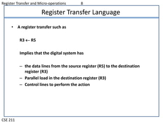
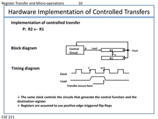
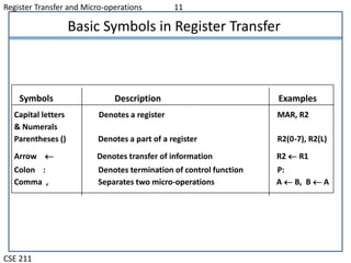
Register Transfer and Micro-operations
CSE 211
Overview
 Register Transfer Language
 Register Transfer
 Bus and Memory Transfers
 Logic Micro-operations
 Shift Micro-operations
 Arithmetic Logic Shift Unit
Register Transfer and Micro-operations 2
CSE 211
Register Transfer Language
 Combinational and sequential circuits can be used to create simple
digital systems.
 These are the low-level building blocks of a digital computer.
 Simple digital systems are frequently characterized in terms of
 the registers they contain, and
 the operations that are performed on data stored in them
 The operations executed on the data in registers are called micro-
operations e.g. shift, count, clear and load
Register Transfer and Micro-operations 3
CSE 211
Register Transfer Language
Set of registers and their functions
 Sequence of microoperations performed on binary
information stored in registers
Control signals that initiate the sequence of micro-
operations (to perform the functions)
Internal hardware organization of a digital computer :
Register Transfer and Micro-operations 4
CSE 211
Register Transfer Language
 Rather than specifying a digital system in words, a specific notation is
used, Register Transfer Language
 The symbolic notation used to describe the micro operation transfer
among register is called a register transfer language
 For any function of the computer, the register transfer language can be
used to describe the (sequence of) micro-operations
 Register transfer language
 A symbolic language
 A convenient tool for describing the internal organization of
digital computers in concise/precise manner.
 Can also be used to facilitate the design process of digital
systems.
Register Transfer and Micro-operations 5
CSE 211
Register Transfer Language
 Registers are designated by capital letters, sometimes followed by
numbers (e.g., A, R13, IR)
 Often the names indicate function:
 MAR - memory address register
 PC - program counter
 IR - instruction register
 Registers and their contents can be viewed and represented in various
ways
 A register can be viewed as a single entity:
MAR
Register Transfer and Micro-operations 6
CSE 211
Register Transfer Language
R1
Register
Numbering of bits
Showing individual bits
Subfields
PC(H) PC(L)
15 8 7 0
- a register
- portion of a register
- a bit of a register
• Common ways of drawing the block diagram of a register
7 6 5 4 3 2 1 0
R2
15 0
• Designation of a register
Register Transfer and Micro-operations 7
CSE 211
Register Transfer Language
• Copying the contents of one register to another is a register transfer
• A register transfer is indicated as
R2  R1
 In this case the contents of register R1 are copied (loaded) into
register R2
 A simultaneous transfer of all bits from the source R1 to the
destination register R2, during one clock pulse
 Note that this is a non-destructive; i.e. the contents of R1 are not
altered by copying (loading) them to R2
Register Transfer and Micro-operations 8
CSE 211
Register Transfer Language
• A register transfer such as
R3  R5
Implies that the digital system has
– the data lines from the source register (R5) to the destination
register (R3)
– Parallel load in the destination register (R3)
– Control lines to perform the action
Register Transfer and Micro-operations 9
CSE 211
Control Functions
 Often actions need to only occur if a certain condition is true
 This is similar to an “if” statement in a programming language
 In digital systems, this is often done via a control signal, called a control
function
 If the signal is 1, the action takes place
 This is represented as:
P: R2  R1
Which means “if P = 1, then load the contents of register R1 into
register R2”, i.e., if (P = 1) then (R2  R1)
Register Transfer and Micro-operations 10
CSE 211
Hardware Implementation of Controlled Transfers
Implementation of controlled transfer
P: R2 R1
Block diagram
Timing diagram
Clock
Transfer occurs here
R2
R1
Control
Circuit
LoadP
n
Clock
Load
t t+1
 The same clock controls the circuits that generate the control function and the
destination register
 Registers are assumed to use positive-edge-triggered flip-flops
Register Transfer and Micro-operations 11
CSE 211
Basic Symbols in Register Transfer
Capital letters Denotes a register MAR, R2
& Numerals
Parentheses () Denotes a part of a register R2(0-7), R2(L)
Arrow  Denotes transfer of information R2  R1
Colon : Denotes termination of control function P:
Comma , Separates two micro-operations A  B, B  A
Symbols Description Examples

Register Transfer Language

  • 1.
    Register Transfer andMicro-operations CSE 211 Overview  Register Transfer Language  Register Transfer  Bus and Memory Transfers  Logic Micro-operations  Shift Micro-operations  Arithmetic Logic Shift Unit
  • 2.
    Register Transfer andMicro-operations 2 CSE 211 Register Transfer Language  Combinational and sequential circuits can be used to create simple digital systems.  These are the low-level building blocks of a digital computer.  Simple digital systems are frequently characterized in terms of  the registers they contain, and  the operations that are performed on data stored in them  The operations executed on the data in registers are called micro- operations e.g. shift, count, clear and load
  • 3.
    Register Transfer andMicro-operations 3 CSE 211 Register Transfer Language Set of registers and their functions  Sequence of microoperations performed on binary information stored in registers Control signals that initiate the sequence of micro- operations (to perform the functions) Internal hardware organization of a digital computer :
  • 4.
    Register Transfer andMicro-operations 4 CSE 211 Register Transfer Language  Rather than specifying a digital system in words, a specific notation is used, Register Transfer Language  The symbolic notation used to describe the micro operation transfer among register is called a register transfer language  For any function of the computer, the register transfer language can be used to describe the (sequence of) micro-operations  Register transfer language  A symbolic language  A convenient tool for describing the internal organization of digital computers in concise/precise manner.  Can also be used to facilitate the design process of digital systems.
  • 5.
    Register Transfer andMicro-operations 5 CSE 211 Register Transfer Language  Registers are designated by capital letters, sometimes followed by numbers (e.g., A, R13, IR)  Often the names indicate function:  MAR - memory address register  PC - program counter  IR - instruction register  Registers and their contents can be viewed and represented in various ways  A register can be viewed as a single entity: MAR
  • 6.
    Register Transfer andMicro-operations 6 CSE 211 Register Transfer Language R1 Register Numbering of bits Showing individual bits Subfields PC(H) PC(L) 15 8 7 0 - a register - portion of a register - a bit of a register • Common ways of drawing the block diagram of a register 7 6 5 4 3 2 1 0 R2 15 0 • Designation of a register
  • 7.
    Register Transfer andMicro-operations 7 CSE 211 Register Transfer Language • Copying the contents of one register to another is a register transfer • A register transfer is indicated as R2  R1  In this case the contents of register R1 are copied (loaded) into register R2  A simultaneous transfer of all bits from the source R1 to the destination register R2, during one clock pulse  Note that this is a non-destructive; i.e. the contents of R1 are not altered by copying (loading) them to R2
  • 8.
    Register Transfer andMicro-operations 8 CSE 211 Register Transfer Language • A register transfer such as R3  R5 Implies that the digital system has – the data lines from the source register (R5) to the destination register (R3) – Parallel load in the destination register (R3) – Control lines to perform the action
  • 9.
    Register Transfer andMicro-operations 9 CSE 211 Control Functions  Often actions need to only occur if a certain condition is true  This is similar to an “if” statement in a programming language  In digital systems, this is often done via a control signal, called a control function  If the signal is 1, the action takes place  This is represented as: P: R2  R1 Which means “if P = 1, then load the contents of register R1 into register R2”, i.e., if (P = 1) then (R2  R1)
  • 10.
    Register Transfer andMicro-operations 10 CSE 211 Hardware Implementation of Controlled Transfers Implementation of controlled transfer P: R2 R1 Block diagram Timing diagram Clock Transfer occurs here R2 R1 Control Circuit LoadP n Clock Load t t+1  The same clock controls the circuits that generate the control function and the destination register  Registers are assumed to use positive-edge-triggered flip-flops
  • 11.
    Register Transfer andMicro-operations 11 CSE 211 Basic Symbols in Register Transfer Capital letters Denotes a register MAR, R2 & Numerals Parentheses () Denotes a part of a register R2(0-7), R2(L) Arrow  Denotes transfer of information R2  R1 Colon : Denotes termination of control function P: Comma , Separates two micro-operations A  B, B  A Symbols Description Examples