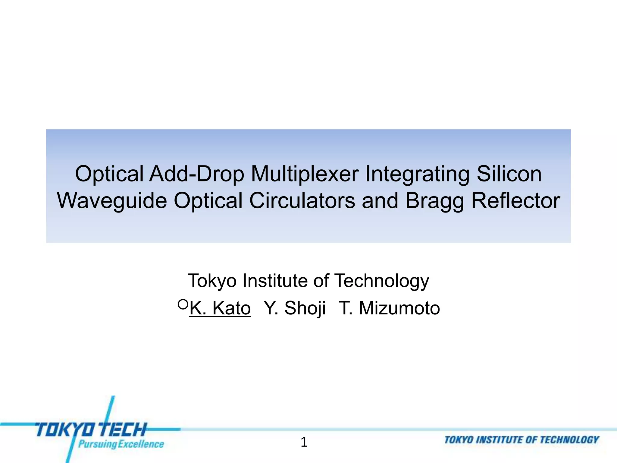
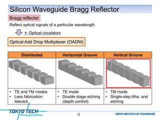
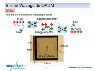
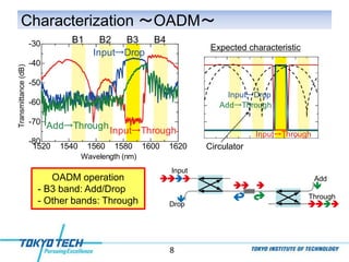
An optical add-drop multiplexer was developed by integrating silicon waveguide optical circulators and a Bragg reflector. A silicon waveguide Bragg reflector was fabricated that achieved 30 dB reflection for TM mode signals of a particular wavelength. An optical add-drop multiplexer device was demonstrated by combining two optical circulators with the Bragg reflector. It was able to add and drop signal light of a specific wavelength while passing other wavelengths through.
![3
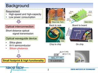
Silicon Waveguide Optical Circulator
Port2
Port1 Port4
Port3
Nonreciprocal optical path circulation
• Integratable with other components
• Maximum isolation of 33 dB
• TM mode operation
・・・
• Optical add-drop multiplexer
• Dispersion compensator
• Bidirectional transmission system
Optical circulator
Silicon waveguide optical circulator
T. Mizumoto, et al., Proc. SPIE, 8988, 89880C (2014).
1530 1540 1550 1560 1570
-80
-60
-40
-20
Wavelength [nm]
Transmittance[dB]
Port 1 → Port 2
Port 2 → Port 1
33 dB
Port1
Port4
Port2
Port3 Si
SiO2
Ce:YIG
3 dB directional coupler
Non-reciprocal
Reciprocal phase shifter (RPS)
Magnetic field
phase shifter (NPS)](https://image.slidesharecdn.com/151027mockatoystm-161031144558/85/Optical-Add-Drop-Multiplexer-Integrating-Silicon-Waveguide-Optical-Circulators-and-Bragg-Reflector-3-320.jpg)
![6
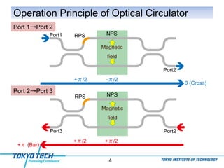
Characterization ~Bragg Reflector~
30 dB Bragg reflection
(TM mode)
1540 1560 1580 1600 1620
-70
-60
-50
-40
-30
-20
Wavelength [nm]
Transmittance[dB]
Ref w/o Ce:YIG
Bragg reflector
Ref w/ Ce:YIG
Waveguide width
Waveguide height
Grating period
Groove depth
Groove length
184 nm
368 nm
70 nm
220 nm
550 nm
Grooves were repeated 500 times
220 nm
550 nm
Si
SiO2
Ce:YIG](https://image.slidesharecdn.com/151027mockatoystm-161031144558/85/Optical-Add-Drop-Multiplexer-Integrating-Silicon-Waveguide-Optical-Circulators-and-Bragg-Reflector-6-320.jpg)


![[Graham t. reed]_silicon_photonics__an_introductio(z-lib.org)](https://cdn.slidesharecdn.com/ss_thumbnails/grahamt-200704124405-thumbnail.jpg?width=640&height=640&fit=bounds)


