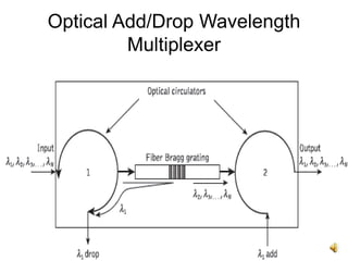
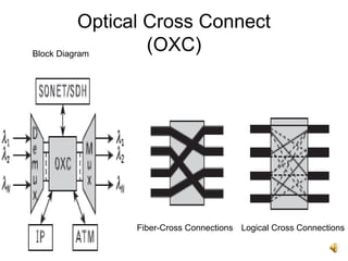
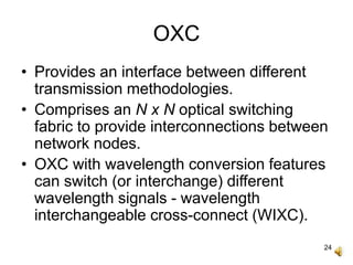
1
WDM Standards and
Components
MEC
2
Contents
• System Features.
• WDM Standards.
• Optical Network.
• Optical/WDM Components.
- Multiplexer.
- Demultiplexer.
- Switches.
- OADM and ROADM.
- OXC and MG-OXC.
3
WDM System Features
• Capacity Upgradation:
- Each wavelength supports independent
network channel of a few Gb/s.
- Capacity enhancement with each
additional channel.
• Transparency:
- Information can be sent simultaneously
and independently over the same fiber.
- No need for a common signal structure.
4
WDM System Features
• Wavelength Routing:
- Pure optical end to end connection
between users.
- Light paths routed and switched at
intermediate network nodes.
- Wavelength conversion along the route
permitted.
5
WDM Standards*
• Analogous to FDM.
• Standards developed by ITU**.
• Channel spacings specified in terms of
frequency.
• Fixed frequency spacing since frequency
of laser is fixed when locked to a particular
operating mode.
6
WDM Standards*
• G692 – Optical Interfaces for Multichannel
Systems with Optical Amplifiers specifies
channel selection from a grid of
frequencies referenced to 193.100 THz
(1552.524 nm) and spacing them 100 GHz
apart (0.8 nm at 1550 nm).
• G692 suggests alternate spacings of 50
and 200 GHz (spectral widths of 0.4 and
1.6 nm at 1550 nm).
7
WDM Standards*
• G694.1 – DWDM wavelength ranges and
spacings, WDM operation in S-, C- and L-
Bands for high quality, high rate MAN and
WAN services.
• G694.2 - CWDM wavelength ranges and
spacings – 18 wavelengths, range 1270-1610
nm spaced by 20 nm with wavelength drift
tolerances of +/- 2 nm.
• G652, G653 & G655 - targeted transmission
distances on single mode fibers for CWDM.
8
Optical Network Structure
9
Optical Network
• Optical nodes interconnected with optical
fiber links.
• Optical node as a multifunctional element -
transceiver unit capable of receiving,
transmitting and processing the optical
signal.
• Optical fibers provide point-to-point
physical connections between network
nodes.
10
Optical Network
• Point-to-point fiber links used to establish
logical links.
• Destination node reached by travelling
through one or more intermediate nodes in
single or multiple hops.
• Each channel assigned a specific signal
wavelength from source to destination.
• A signal carried on a dedicated wavelength
from source to destination node called
‘lightpath’.
11
Optical Network
• Controlling mechanism required to provide
for data flow during its transmission.
• Need to authenticate data transportation
between each transmitting and receiving
node.
• Unidirectional or bidirectional transmission
over the same single optical fiber.
12
Network Topologies
Bus Ring Star Mesh
13
Node Elements
• Node as a router to direct an input signal
wavelength to a specified output port.
• Wavelength router comprises of optical
couplers.
• Four different router functions:
- Demultiplexing.
- Multiplexing.
- Optical Add/Drop Multiplexer – OADM.
- Optical Switch.
• Reconfigurable OADM (ROADM) – OADM
+ Optical Switch.
14
Wavelength Demultiplexer
• Analogous to DEMUX in
electronics.
• Splits an optical signal at
input port 1 containing
two signal wavelengths
(i.e. λ1 and λ2).
• Routes them to ports 2
and 3.
1x2 wavelength
demultiplexer
15
Wavelength Multiplexer
• Analogous to MUX in
electronics.
• Combines two wavelength
signals λ1 and λ2 at ports 1
and 2.
• Multiplexed optical signal
available at port 3.
3 port wavelength
multiplexer
16
OADM
• Optical Add-Drop Multiplexer
(OADM) comprises of a
wavelength add/drop device
(WADD).
• Adds or Drops wavelengths
while multiplexing different
wavelengths.
• Fixed OADM drops a
particular wavelength, adds
another specific wavelength.
17
Optical Switch
• Wavelengths switched and
multiplexed at the output
ports.
• Possible to produce optical
switch with greater number
of ports (say N x N).
2 x 2 optical switch
18
ROADM
• Combines an OADM and an
optical switch.
• Can drop one or more
wavelength channels after
demultiplexing a wavelength
multiplexed signal.
• Can also add a new single
or more wavelength
channels through an optical
switch.
• Brings together all desired
wavelength channels at the
output.
19
ROADM
• Passive ROADM can be constructed using
a fiber Bragg grating and an optical
circulator.
• Useful in providing for simple optical
network topologies.
• Cannot facilitate complex mesh topologies
with large number of nodes - cross
connects required.
20
Optical Circulators
An optical signal can leave the device at an end terminal or it
can continue to flow towards the next connected isolator.
Optical signal follows a closed loop.
21
Optical Add/Drop Wavelength
Multiplexer
22
Optical Cross Connect
(OXC)Block Diagram
Fiber-Cross Connections Logical Cross Connections
23
OXC
• Capable of switching connection between
two interfaced points.
• Large number of wavelength signals can
be demultiplexed at the input ports.
• Internally connected to the desired output
ports.
• Different wavelength signals multiplexed
for onward transmission.
24
OXC
• Provides an interface between different
transmission methodologies.
• Comprises an N x N optical switching
fabric to provide interconnections between
network nodes.
• OXC with wavelength conversion features
can switch (or interchange) different
wavelength signals - wavelength
interchangeable cross-connect (WIXC).
25
OXC
• OXC with optoelectronic conversions known
as an opaque OXC.
• OXC with all-optical/optical wavelength
converters known as a transparent OXC.
• N x N optical switching fabric in an OXC
facilitates either physical (fiber) or logical
interconnections.
• Logical wavelength interconnection for
multiple wavelength signals.
26
Multigranular Optical Cross-
Connect ((MG-OXC)
• Multilayered OXC - each layer apart from
providing specific switching capability can
be connected to another layer.
• Logical interconnection (i.e. single
wavelength, multiple wavelengths,
wavebands*) & physical interconnections
(i.e. fiber cross-connect) combined together
in a multilayer structure.
• Can be routed individually/as wavebands*.
27
Thank You

Wdm standards and components

  • 1.
  • 2.
    2 Contents • System Features. •WDM Standards. • Optical Network. • Optical/WDM Components. - Multiplexer. - Demultiplexer. - Switches. - OADM and ROADM. - OXC and MG-OXC.
  • 3.
    3 WDM System Features •Capacity Upgradation: - Each wavelength supports independent network channel of a few Gb/s. - Capacity enhancement with each additional channel. • Transparency: - Information can be sent simultaneously and independently over the same fiber. - No need for a common signal structure.
  • 4.
    4 WDM System Features •Wavelength Routing: - Pure optical end to end connection between users. - Light paths routed and switched at intermediate network nodes. - Wavelength conversion along the route permitted.
  • 5.
    5 WDM Standards* • Analogousto FDM. • Standards developed by ITU**. • Channel spacings specified in terms of frequency. • Fixed frequency spacing since frequency of laser is fixed when locked to a particular operating mode.
  • 6.
    6 WDM Standards* • G692– Optical Interfaces for Multichannel Systems with Optical Amplifiers specifies channel selection from a grid of frequencies referenced to 193.100 THz (1552.524 nm) and spacing them 100 GHz apart (0.8 nm at 1550 nm). • G692 suggests alternate spacings of 50 and 200 GHz (spectral widths of 0.4 and 1.6 nm at 1550 nm).
  • 7.
    7 WDM Standards* • G694.1– DWDM wavelength ranges and spacings, WDM operation in S-, C- and L- Bands for high quality, high rate MAN and WAN services. • G694.2 - CWDM wavelength ranges and spacings – 18 wavelengths, range 1270-1610 nm spaced by 20 nm with wavelength drift tolerances of +/- 2 nm. • G652, G653 & G655 - targeted transmission distances on single mode fibers for CWDM.
  • 8.
  • 9.
    9 Optical Network • Opticalnodes interconnected with optical fiber links. • Optical node as a multifunctional element - transceiver unit capable of receiving, transmitting and processing the optical signal. • Optical fibers provide point-to-point physical connections between network nodes.
  • 10.
    10 Optical Network • Point-to-pointfiber links used to establish logical links. • Destination node reached by travelling through one or more intermediate nodes in single or multiple hops. • Each channel assigned a specific signal wavelength from source to destination. • A signal carried on a dedicated wavelength from source to destination node called ‘lightpath’.
  • 11.
    11 Optical Network • Controllingmechanism required to provide for data flow during its transmission. • Need to authenticate data transportation between each transmitting and receiving node. • Unidirectional or bidirectional transmission over the same single optical fiber.
  • 12.
  • 13.
    13 Node Elements • Nodeas a router to direct an input signal wavelength to a specified output port. • Wavelength router comprises of optical couplers. • Four different router functions: - Demultiplexing. - Multiplexing. - Optical Add/Drop Multiplexer – OADM. - Optical Switch. • Reconfigurable OADM (ROADM) – OADM + Optical Switch.
  • 14.
    14 Wavelength Demultiplexer • Analogousto DEMUX in electronics. • Splits an optical signal at input port 1 containing two signal wavelengths (i.e. λ1 and λ2). • Routes them to ports 2 and 3. 1x2 wavelength demultiplexer
  • 15.
    15 Wavelength Multiplexer • Analogousto MUX in electronics. • Combines two wavelength signals λ1 and λ2 at ports 1 and 2. • Multiplexed optical signal available at port 3. 3 port wavelength multiplexer
  • 16.
    16 OADM • Optical Add-DropMultiplexer (OADM) comprises of a wavelength add/drop device (WADD). • Adds or Drops wavelengths while multiplexing different wavelengths. • Fixed OADM drops a particular wavelength, adds another specific wavelength.
  • 17.
    17 Optical Switch • Wavelengthsswitched and multiplexed at the output ports. • Possible to produce optical switch with greater number of ports (say N x N). 2 x 2 optical switch
  • 18.
    18 ROADM • Combines anOADM and an optical switch. • Can drop one or more wavelength channels after demultiplexing a wavelength multiplexed signal. • Can also add a new single or more wavelength channels through an optical switch. • Brings together all desired wavelength channels at the output.
  • 19.
    19 ROADM • Passive ROADMcan be constructed using a fiber Bragg grating and an optical circulator. • Useful in providing for simple optical network topologies. • Cannot facilitate complex mesh topologies with large number of nodes - cross connects required.
  • 20.
    20 Optical Circulators An opticalsignal can leave the device at an end terminal or it can continue to flow towards the next connected isolator. Optical signal follows a closed loop.
  • 21.
  • 22.
    22 Optical Cross Connect (OXC)BlockDiagram Fiber-Cross Connections Logical Cross Connections
  • 23.
    23 OXC • Capable ofswitching connection between two interfaced points. • Large number of wavelength signals can be demultiplexed at the input ports. • Internally connected to the desired output ports. • Different wavelength signals multiplexed for onward transmission.
  • 24.
    24 OXC • Provides aninterface between different transmission methodologies. • Comprises an N x N optical switching fabric to provide interconnections between network nodes. • OXC with wavelength conversion features can switch (or interchange) different wavelength signals - wavelength interchangeable cross-connect (WIXC).
  • 25.
    25 OXC • OXC withoptoelectronic conversions known as an opaque OXC. • OXC with all-optical/optical wavelength converters known as a transparent OXC. • N x N optical switching fabric in an OXC facilitates either physical (fiber) or logical interconnections. • Logical wavelength interconnection for multiple wavelength signals.
  • 26.
    26 Multigranular Optical Cross- Connect((MG-OXC) • Multilayered OXC - each layer apart from providing specific switching capability can be connected to another layer. • Logical interconnection (i.e. single wavelength, multiple wavelengths, wavebands*) & physical interconnections (i.e. fiber cross-connect) combined together in a multilayer structure. • Can be routed individually/as wavebands*.
  • 27.