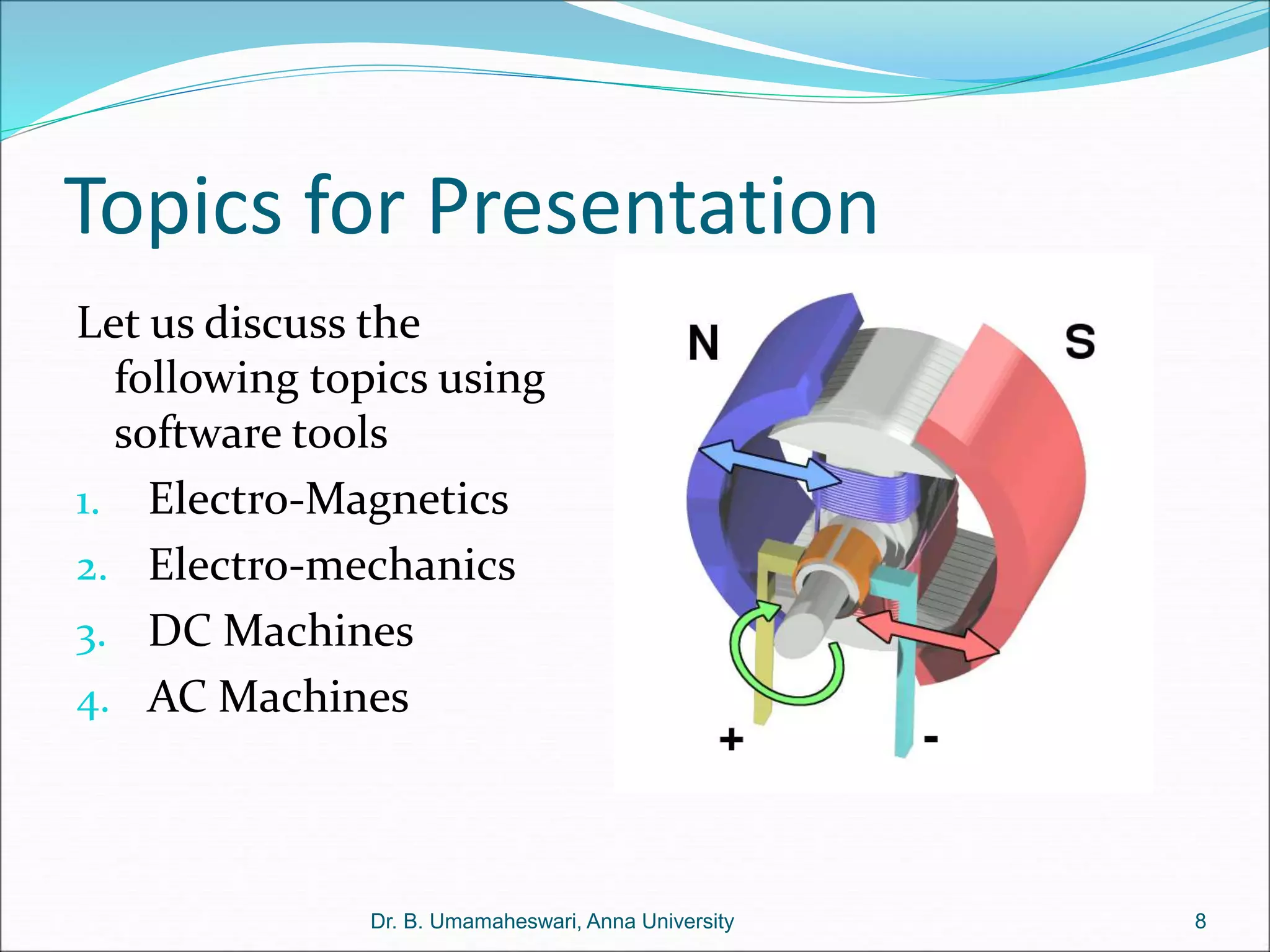
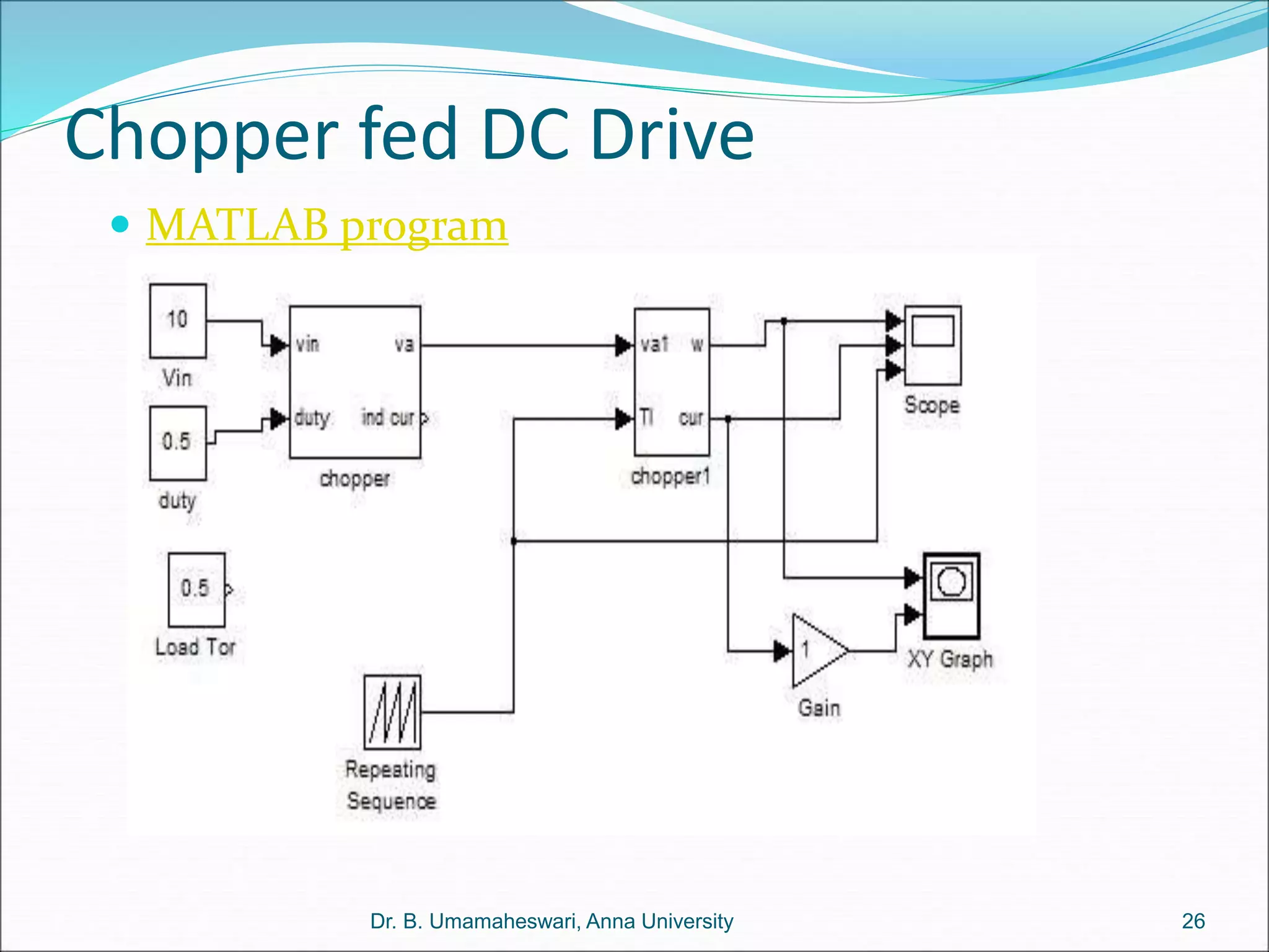
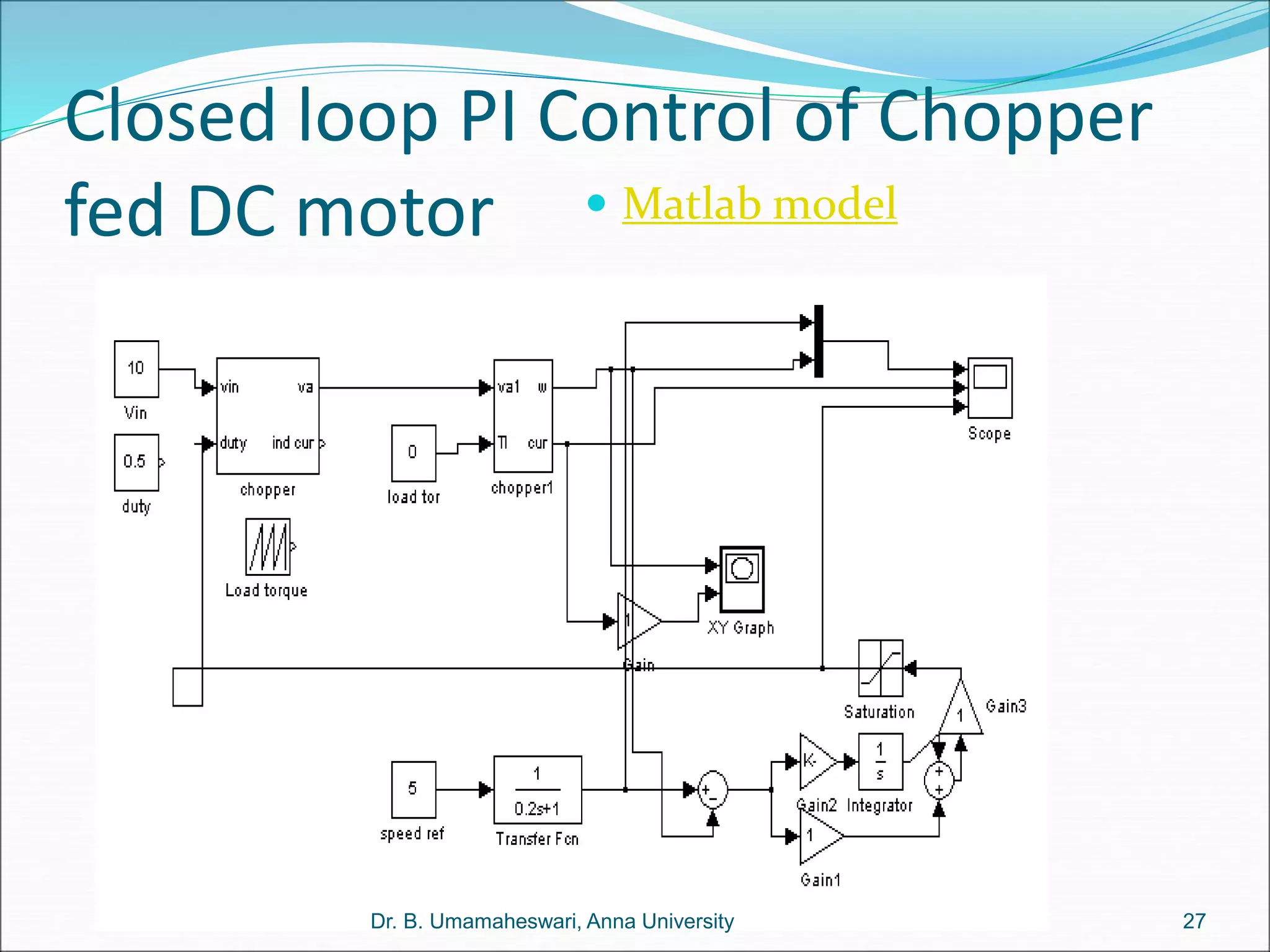
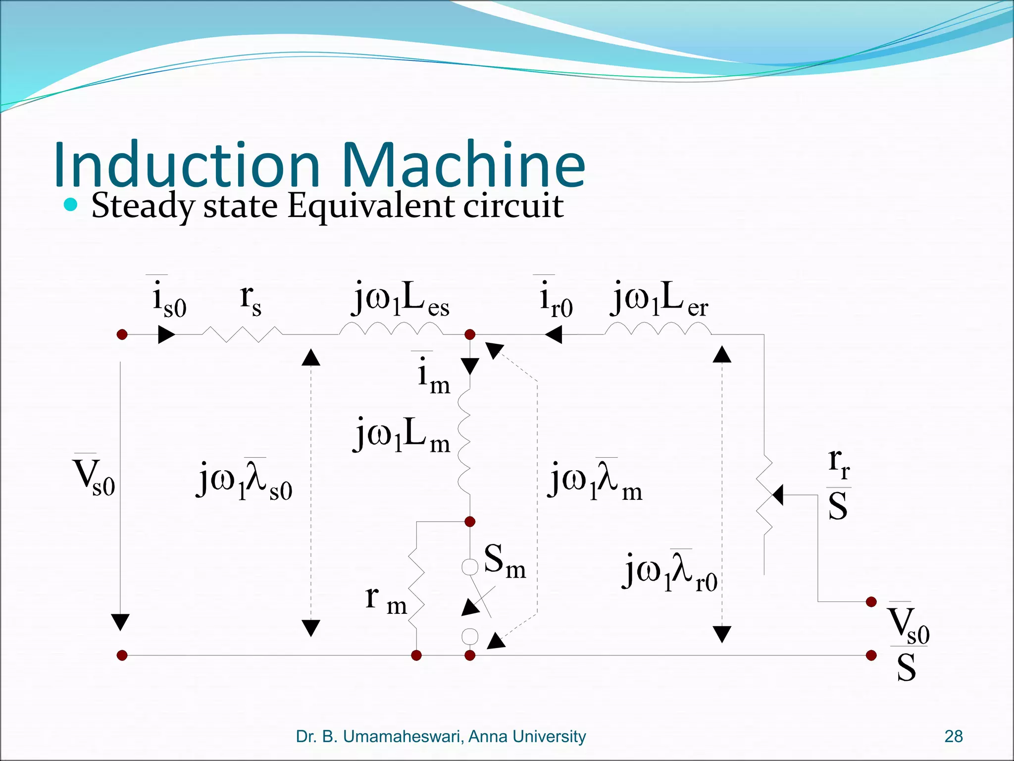
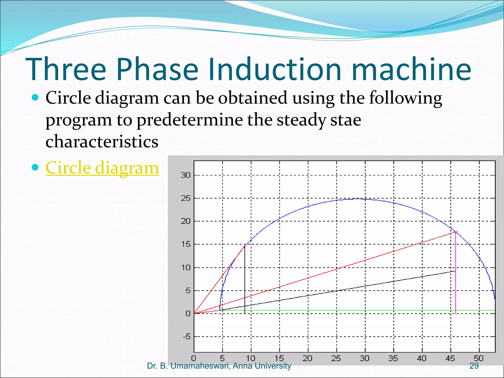
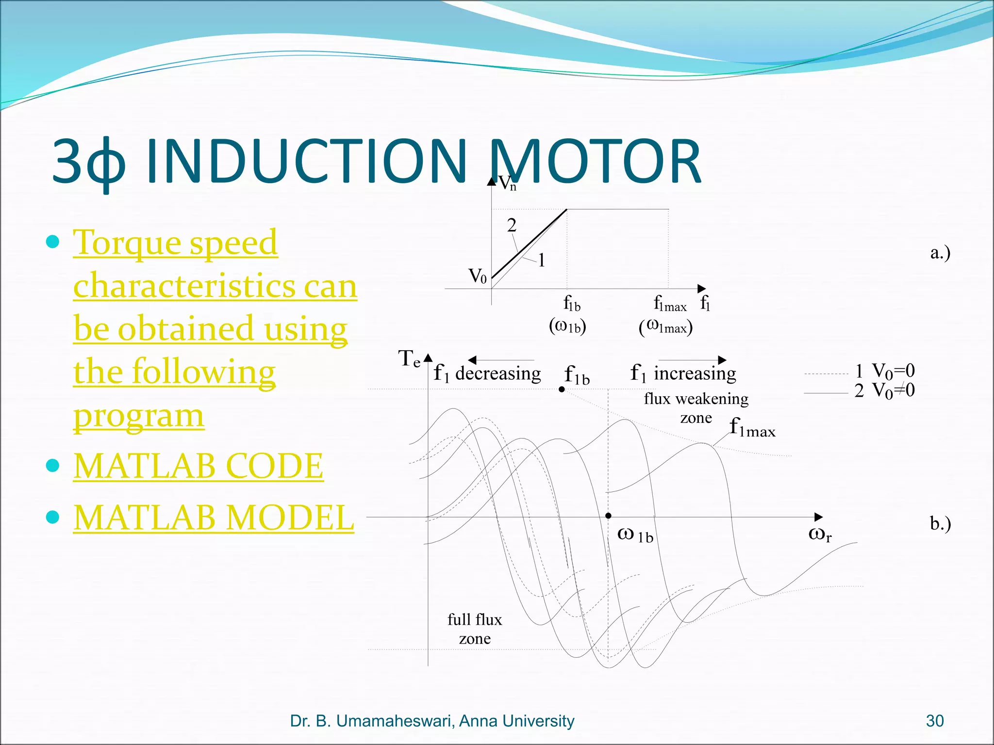
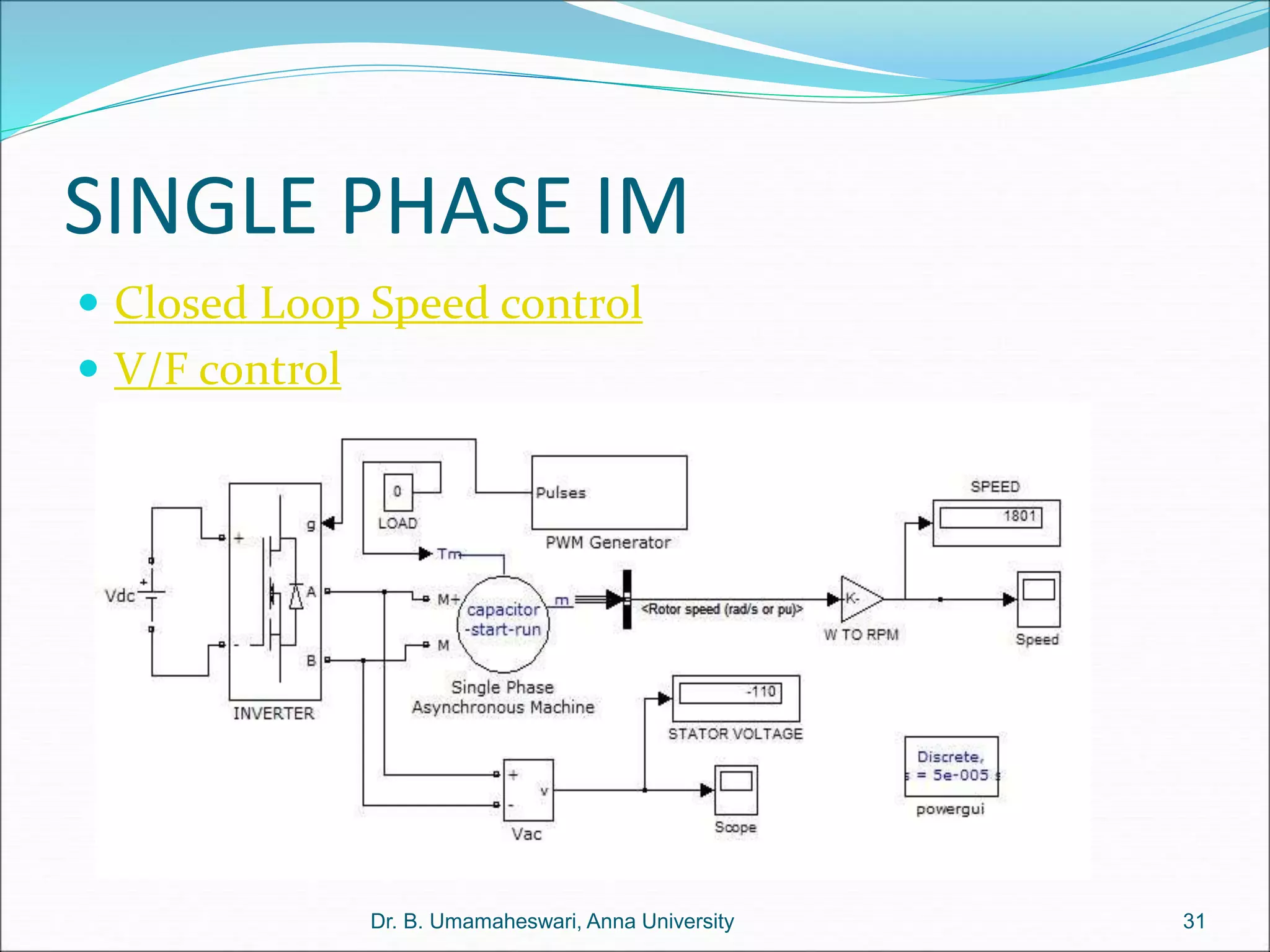
Dr. B. Umamaheswari
Professor
Dept of Electrical & Electronics Engineering,
College of Engineering Guindy
Anna University Chennai
Programs linked in the enclosed slides can be run in MATLAB-
SIMULINK platform
The Teaching and Learning Process
An Effective Teaching-Learning Process may require the
following 5-step sequence
OPTRA
O Organising
P Preparation
T Transmission
R Reception
A Assimilation
Let us present this lecture in these 5-steps
2
Dr. B. Umamaheswari, Anna University
Organizing
The theory of electrical machines is best explained with
analytical models and equivalent circuits. Hence
with the help of software tools these concepts can be
best explained.
Let us start with the following questions
 Why do we need tools like MATLAB?
 How, where and when do we these tools?
 To what level do we use these tools?
3
Dr. B. Umamaheswari, Anna University
Use of software tools
like MATLAB & SIMULINK
 Best used when the theory requires support of
analytical expressions i.e. in the form of mathematical
equations
 The equations could be
 static or dynamic
 Linear or non-linear
 Descriptive or symbolic
 Deterministic or stochastic
4
Dr. B. Umamaheswari, Anna University
Benefits of using software tools
 To have better understanding of the operating
principles
 To visualise the characteristics under various
operating conditions
 To experiment on favourable and non-favourable
conditions
 To design and test the machines for achieving
improved performance
 To create a working platform for pre-determining the
characteristics
5
Dr. B. Umamaheswari, Anna University
Level of Usage
 Digital simulation for complete functional testing -
MATLAB/SIMULINK
 Hardware in Loop (HIL) simulation for real time
testing of the controller –RTW and DAQ
 Power Hardware in Loop Simulation (PHIL) for real
time testing of the Power Electronics and Controller -
RTW and DAQ
 Embedding the control algorithm on a real time
embedded target platform – RT Target link module
6
Dr. B. Umamaheswari, Anna University
Suitability of the tool for Electrical
Drives and Control
 Fields involved
 Electrical Machines
 Power Electronics
 Control Theory and
 embedded platforms
 Study involves understanding of analytical
expressions .
 Simulation of experimental conditions and research
developments is possible.
7
Dr. B. Umamaheswari, Anna University
Topics for Presentation
Let us discuss the
following topics using
software tools
1. Electro-Magnetics
2. Electro-mechanics
3. DC Machines
4. AC Machines
8
Dr. B. Umamaheswari, Anna University
1. Electro-Magnetics
Under Electro-magnetics the following topics are to be
discussed.
 Magnetic circuit – the linear relationship
 Electrical Equivalent
 Inductance
 Rotating magnetic field
 Use software tools for teaching and research
9
Dr. B. Umamaheswari, Anna University
Magnetic circuit
 The Amphere’s Law
A current carrying coil
produces magnetic field
whose intensity is decided
by the permeability of the
medium through which
the flux passes through.
 BH-curve describes the
permeability of a medium
 For linear assumption
Permeability is constant
7
0 4 1000
r
  

 
x10
/ *
R g a


10
Dr. B. Umamaheswari, Anna University
.
H dl Ni


Electrical equivalent
For the purpose of analysis,
an equivalent electrical
circuit can be drawn.
 Flux => current
 MMF => emf
 Reluctance => Resistance
0
( )
( )
i g
g
g i g i
Ni R R
l
Ni B H B l


 
 
11
Dr. B. Umamaheswari, Anna University
 Linear BH- relationship Program1
 Non-linear BH relationship
program2
Linear case
( )..(1)
i g
Ni R R
  
12
Dr. B. Umamaheswari, Anna University
 Linear BH- relationship
 Air gap reluctance is Rg
 Core Reluctance is Rl << Rg
 Using voltage division rule, the greater Reluctance
part gets the greater MMF sahre
 Hence upon the supplied MMF ‘Ni” most of the
MMF is dropped or available across the air-gap
 Program1 describes the flux variation (equation 1)
as a function of airgap length.
 Program1
Non-Linear case
13
Dr. B. Umamaheswari, Anna University
 Non-linear BH relationship
 Core reluctance is a function of flux
 Use equation (3) to get Hl for various values of Bg.
 Superimpose the obtained Hl vs Bg characteristics on
the BH curve to get Hl and Bg of the given circuit.
 Use Program2 to see the results.
program2
0
( ( ) )..(2)
( ) ....(3)
i g
g
g i g i
Ni R R
l
Ni B H B l
 

 
 
Inductance
 Self Inductance of a coil
describes how much of the flux
links the coil produced by its
own current
 Mutual inductance of a coil
describes how much of the flux
links the coil produced by
current in the other coils.
 Inductance in a salient pole
machine is simulated using the
following program
 MATLAB Program
2
( )
N a
L
l



14
Dr. B. Umamaheswari, Anna University
Generation of Sinusoidal MMF
  t
sin
x
sin
F
t
,
x
F 1
m
1
a
1
a 





15
Dr. B. Umamaheswari, Anna University
 With two sets of coils of carrying currents in the
opposite directions Square -MMF waveshape can
be produced.
 Using appropriate Fourier relationship the square
wave can be resolved into fundamental and its
harmonic components .
Rotating magnetic field
 Rotating magnetic field can
be produced by Two, Three
or more phases equally
placed along the periphery
of a circular path
 Rotating MMF of Two
phase and Two pole
machine is illustrated in the
following program
16
Dr. B. Umamaheswari, Anna University
 MATLAB Program
Electro-mechanics
 A coil (Armature) placed in the airgap subjected to
time-varying magnetic field experiences an induced
voltage { Faraday’s Law}
 It circulates current to oppose its cause (Lenz aw)
 Interaction of magnetic flux with armature current
produces mechanical force
 Direction of force is given by Fleming’s Left Hand
Rule.
 This is the principle of motoring
17
Dr. B. Umamaheswari, Anna University
Principle of
Motoring & Generation
Dr. B. Umamaheswari, Anna University 18
Simulation of DC Machine
characteristics
 Equivalent circuit of DC machine with separate
excitation is illustrated in the figure
 Using software simulation the characteristics can be
studied
19
Dr. B. Umamaheswari, Anna University
MATLAB CODING
I. DC MOTOR
II. EQUIVALENT CIRCUIT
20
Dr. B. Umamaheswari, Anna University
Separately excited
 Torque speed characteristics
 Matlab model
 Matlab code
21
Dr. B. Umamaheswari, Anna University
Other EXCITATION SCHEMES
22
Dr. B. Umamaheswari, Anna University
Load Profiles
23
Dr. B. Umamaheswari, Anna University
Series excited
 Torque speed characteristics
 Matlab model
 Matlab code
24
Dr. B. Umamaheswari, Anna University
Simulation DC-Chopper
performance
 Program_Chopper
25
Dr. B. Umamaheswari, Anna University
Chopper fed DC Drive
 MATLAB program
26
Dr. B. Umamaheswari, Anna University
Closed loop PI Control of Chopper
fed DC motor  Matlab model
27
Dr. B. Umamaheswari, Anna University
Induction Machine
 Steady state Equivalent circuit
28
Dr. B. Umamaheswari, Anna University
Three Phase Induction machine
 Circle diagram can be obtained using the following
program to predetermine the steady stae
characteristics
 Circle diagram
29
Dr. B. Umamaheswari, Anna University
3ф INDUCTION MOTOR
 Torque speed
characteristics can
be obtained using
the following
program
 MATLAB CODE
 MATLAB MODEL
30
Dr. B. Umamaheswari, Anna University
SINGLE PHASE IM
 Closed Loop Speed control
 V/F control
Dr. B. Umamaheswari, Anna University 31
References
 Electric Drives by Ion Boldea and S.A. Nasar
 Electrical Machines by Nagrath and Kothari
 Electrical Machines by Fitzerald and Kingsley
 Power Electronics by B. K. Bose
 Control Systems Engineering by I. J. Nagrath and M.
Gopal
32
Dr. B. Umamaheswari, Anna University
B. Umamaheswari
Professor
Department of Electrical and Electronics Engineering
Anna University Chennai
umamahesb@annauniv.edu
This lecture material serves as s a supplement for learning
electrical machines , drives and control for an advanced learner
33
Dr. B. Umamaheswari, Anna University

simulationofelectricalmachines.ppt

  • 1.
    Dr. B. Umamaheswari Professor Deptof Electrical & Electronics Engineering, College of Engineering Guindy Anna University Chennai Programs linked in the enclosed slides can be run in MATLAB- SIMULINK platform
  • 2.
    The Teaching andLearning Process An Effective Teaching-Learning Process may require the following 5-step sequence OPTRA O Organising P Preparation T Transmission R Reception A Assimilation Let us present this lecture in these 5-steps 2 Dr. B. Umamaheswari, Anna University
  • 3.
    Organizing The theory ofelectrical machines is best explained with analytical models and equivalent circuits. Hence with the help of software tools these concepts can be best explained. Let us start with the following questions  Why do we need tools like MATLAB?  How, where and when do we these tools?  To what level do we use these tools? 3 Dr. B. Umamaheswari, Anna University
  • 4.
    Use of softwaretools like MATLAB & SIMULINK  Best used when the theory requires support of analytical expressions i.e. in the form of mathematical equations  The equations could be  static or dynamic  Linear or non-linear  Descriptive or symbolic  Deterministic or stochastic 4 Dr. B. Umamaheswari, Anna University
  • 5.
    Benefits of usingsoftware tools  To have better understanding of the operating principles  To visualise the characteristics under various operating conditions  To experiment on favourable and non-favourable conditions  To design and test the machines for achieving improved performance  To create a working platform for pre-determining the characteristics 5 Dr. B. Umamaheswari, Anna University
  • 6.
    Level of Usage Digital simulation for complete functional testing - MATLAB/SIMULINK  Hardware in Loop (HIL) simulation for real time testing of the controller –RTW and DAQ  Power Hardware in Loop Simulation (PHIL) for real time testing of the Power Electronics and Controller - RTW and DAQ  Embedding the control algorithm on a real time embedded target platform – RT Target link module 6 Dr. B. Umamaheswari, Anna University
  • 7.
    Suitability of thetool for Electrical Drives and Control  Fields involved  Electrical Machines  Power Electronics  Control Theory and  embedded platforms  Study involves understanding of analytical expressions .  Simulation of experimental conditions and research developments is possible. 7 Dr. B. Umamaheswari, Anna University
  • 8.
    Topics for Presentation Letus discuss the following topics using software tools 1. Electro-Magnetics 2. Electro-mechanics 3. DC Machines 4. AC Machines 8 Dr. B. Umamaheswari, Anna University
  • 9.
    1. Electro-Magnetics Under Electro-magneticsthe following topics are to be discussed.  Magnetic circuit – the linear relationship  Electrical Equivalent  Inductance  Rotating magnetic field  Use software tools for teaching and research 9 Dr. B. Umamaheswari, Anna University
  • 10.
    Magnetic circuit  TheAmphere’s Law A current carrying coil produces magnetic field whose intensity is decided by the permeability of the medium through which the flux passes through.  BH-curve describes the permeability of a medium  For linear assumption Permeability is constant 7 0 4 1000 r       x10 / * R g a   10 Dr. B. Umamaheswari, Anna University . H dl Ni  
  • 11.
    Electrical equivalent For thepurpose of analysis, an equivalent electrical circuit can be drawn.  Flux => current  MMF => emf  Reluctance => Resistance 0 ( ) ( ) i g g g i g i Ni R R l Ni B H B l       11 Dr. B. Umamaheswari, Anna University  Linear BH- relationship Program1  Non-linear BH relationship program2
  • 12.
    Linear case ( )..(1) ig Ni R R    12 Dr. B. Umamaheswari, Anna University  Linear BH- relationship  Air gap reluctance is Rg  Core Reluctance is Rl << Rg  Using voltage division rule, the greater Reluctance part gets the greater MMF sahre  Hence upon the supplied MMF ‘Ni” most of the MMF is dropped or available across the air-gap  Program1 describes the flux variation (equation 1) as a function of airgap length.  Program1
  • 13.
    Non-Linear case 13 Dr. B.Umamaheswari, Anna University  Non-linear BH relationship  Core reluctance is a function of flux  Use equation (3) to get Hl for various values of Bg.  Superimpose the obtained Hl vs Bg characteristics on the BH curve to get Hl and Bg of the given circuit.  Use Program2 to see the results. program2 0 ( ( ) )..(2) ( ) ....(3) i g g g i g i Ni R R l Ni B H B l       
  • 14.
    Inductance  Self Inductanceof a coil describes how much of the flux links the coil produced by its own current  Mutual inductance of a coil describes how much of the flux links the coil produced by current in the other coils.  Inductance in a salient pole machine is simulated using the following program  MATLAB Program 2 ( ) N a L l    14 Dr. B. Umamaheswari, Anna University
  • 15.
    Generation of SinusoidalMMF   t sin x sin F t , x F 1 m 1 a 1 a       15 Dr. B. Umamaheswari, Anna University  With two sets of coils of carrying currents in the opposite directions Square -MMF waveshape can be produced.  Using appropriate Fourier relationship the square wave can be resolved into fundamental and its harmonic components .
  • 16.
    Rotating magnetic field Rotating magnetic field can be produced by Two, Three or more phases equally placed along the periphery of a circular path  Rotating MMF of Two phase and Two pole machine is illustrated in the following program 16 Dr. B. Umamaheswari, Anna University  MATLAB Program
  • 17.
    Electro-mechanics  A coil(Armature) placed in the airgap subjected to time-varying magnetic field experiences an induced voltage { Faraday’s Law}  It circulates current to oppose its cause (Lenz aw)  Interaction of magnetic flux with armature current produces mechanical force  Direction of force is given by Fleming’s Left Hand Rule.  This is the principle of motoring 17 Dr. B. Umamaheswari, Anna University
  • 18.
    Principle of Motoring &Generation Dr. B. Umamaheswari, Anna University 18
  • 19.
    Simulation of DCMachine characteristics  Equivalent circuit of DC machine with separate excitation is illustrated in the figure  Using software simulation the characteristics can be studied 19 Dr. B. Umamaheswari, Anna University
  • 20.
    MATLAB CODING I. DCMOTOR II. EQUIVALENT CIRCUIT 20 Dr. B. Umamaheswari, Anna University
  • 21.
    Separately excited  Torquespeed characteristics  Matlab model  Matlab code 21 Dr. B. Umamaheswari, Anna University
  • 22.
    Other EXCITATION SCHEMES 22 Dr.B. Umamaheswari, Anna University
  • 23.
    Load Profiles 23 Dr. B.Umamaheswari, Anna University
  • 24.
    Series excited  Torquespeed characteristics  Matlab model  Matlab code 24 Dr. B. Umamaheswari, Anna University
  • 25.
  • 26.
    Chopper fed DCDrive  MATLAB program 26 Dr. B. Umamaheswari, Anna University
  • 27.
    Closed loop PIControl of Chopper fed DC motor  Matlab model 27 Dr. B. Umamaheswari, Anna University
  • 28.
    Induction Machine  Steadystate Equivalent circuit 28 Dr. B. Umamaheswari, Anna University
  • 29.
    Three Phase Inductionmachine  Circle diagram can be obtained using the following program to predetermine the steady stae characteristics  Circle diagram 29 Dr. B. Umamaheswari, Anna University
  • 30.
    3ф INDUCTION MOTOR Torque speed characteristics can be obtained using the following program  MATLAB CODE  MATLAB MODEL 30 Dr. B. Umamaheswari, Anna University
  • 31.
    SINGLE PHASE IM Closed Loop Speed control  V/F control Dr. B. Umamaheswari, Anna University 31
  • 32.
    References  Electric Drivesby Ion Boldea and S.A. Nasar  Electrical Machines by Nagrath and Kothari  Electrical Machines by Fitzerald and Kingsley  Power Electronics by B. K. Bose  Control Systems Engineering by I. J. Nagrath and M. Gopal 32 Dr. B. Umamaheswari, Anna University
  • 33.
    B. Umamaheswari Professor Department ofElectrical and Electronics Engineering Anna University Chennai umamahesb@annauniv.edu This lecture material serves as s a supplement for learning electrical machines , drives and control for an advanced learner 33 Dr. B. Umamaheswari, Anna University