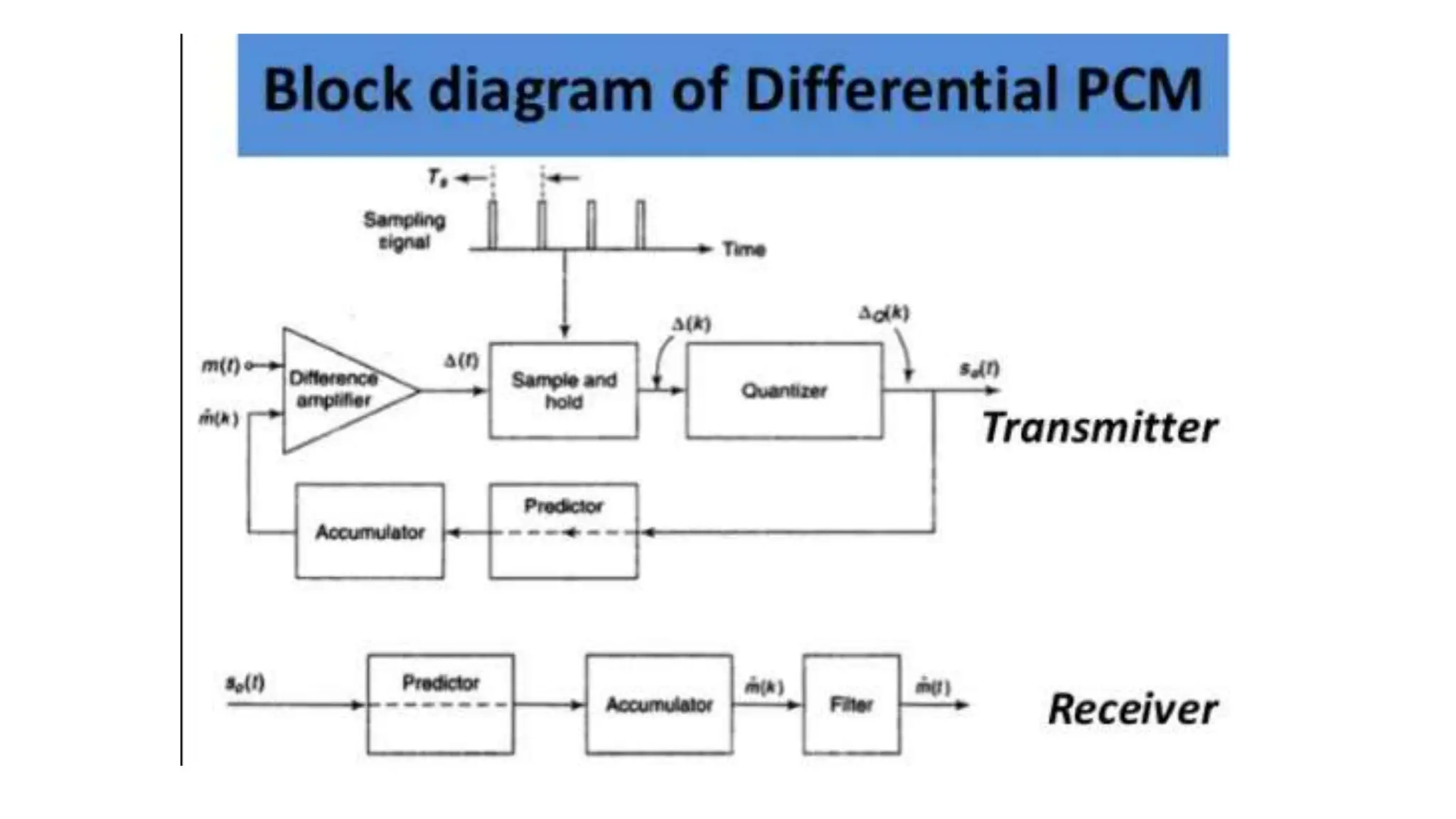
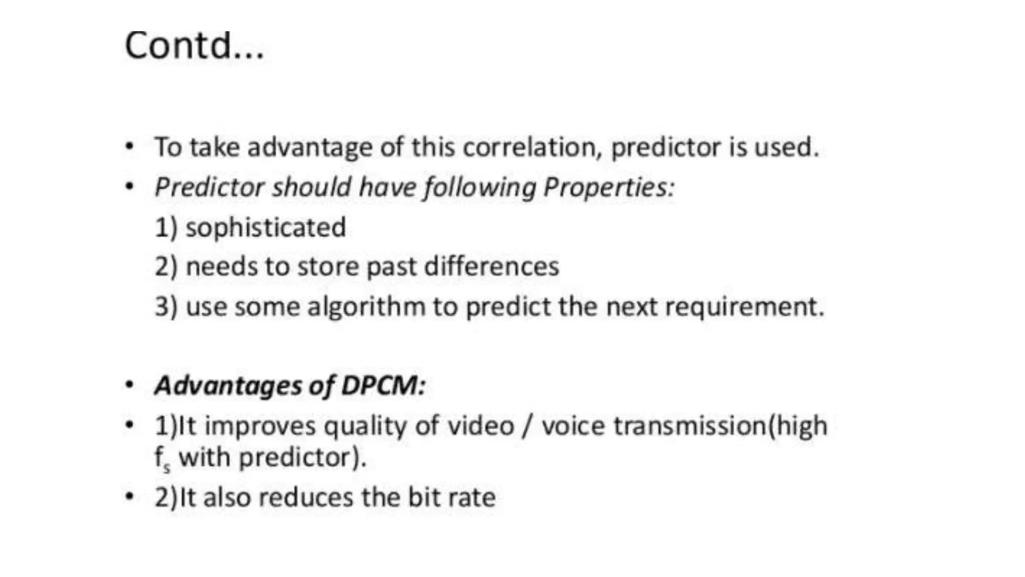
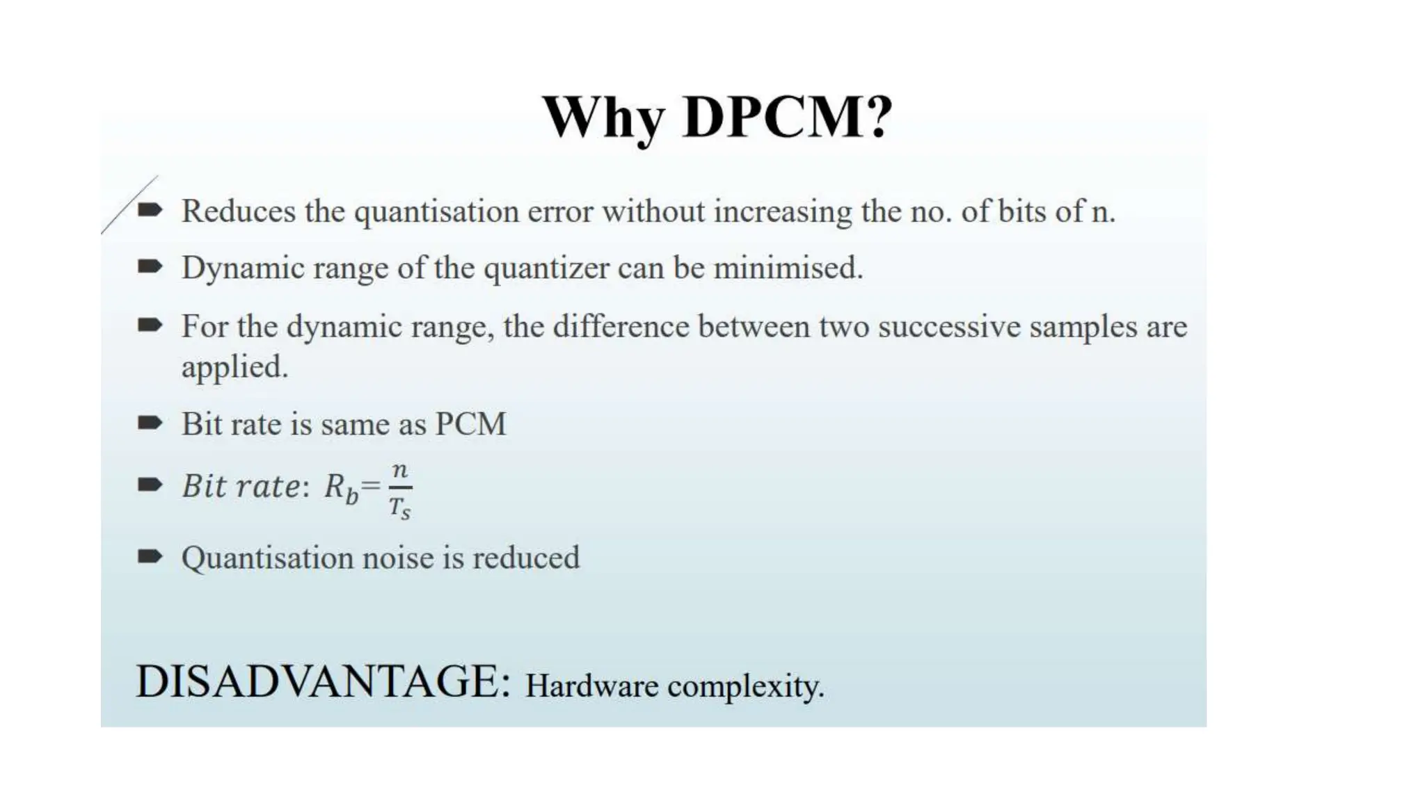
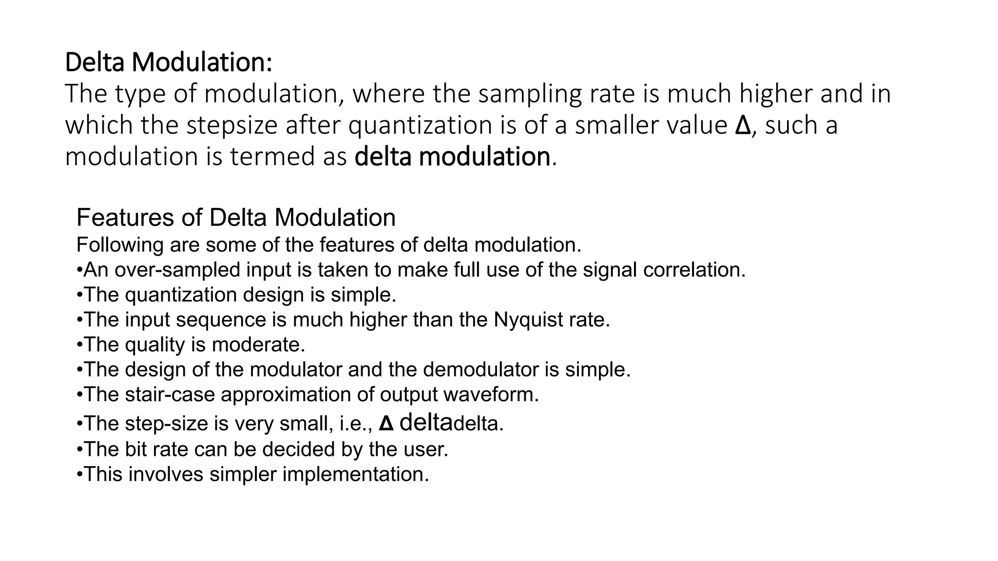
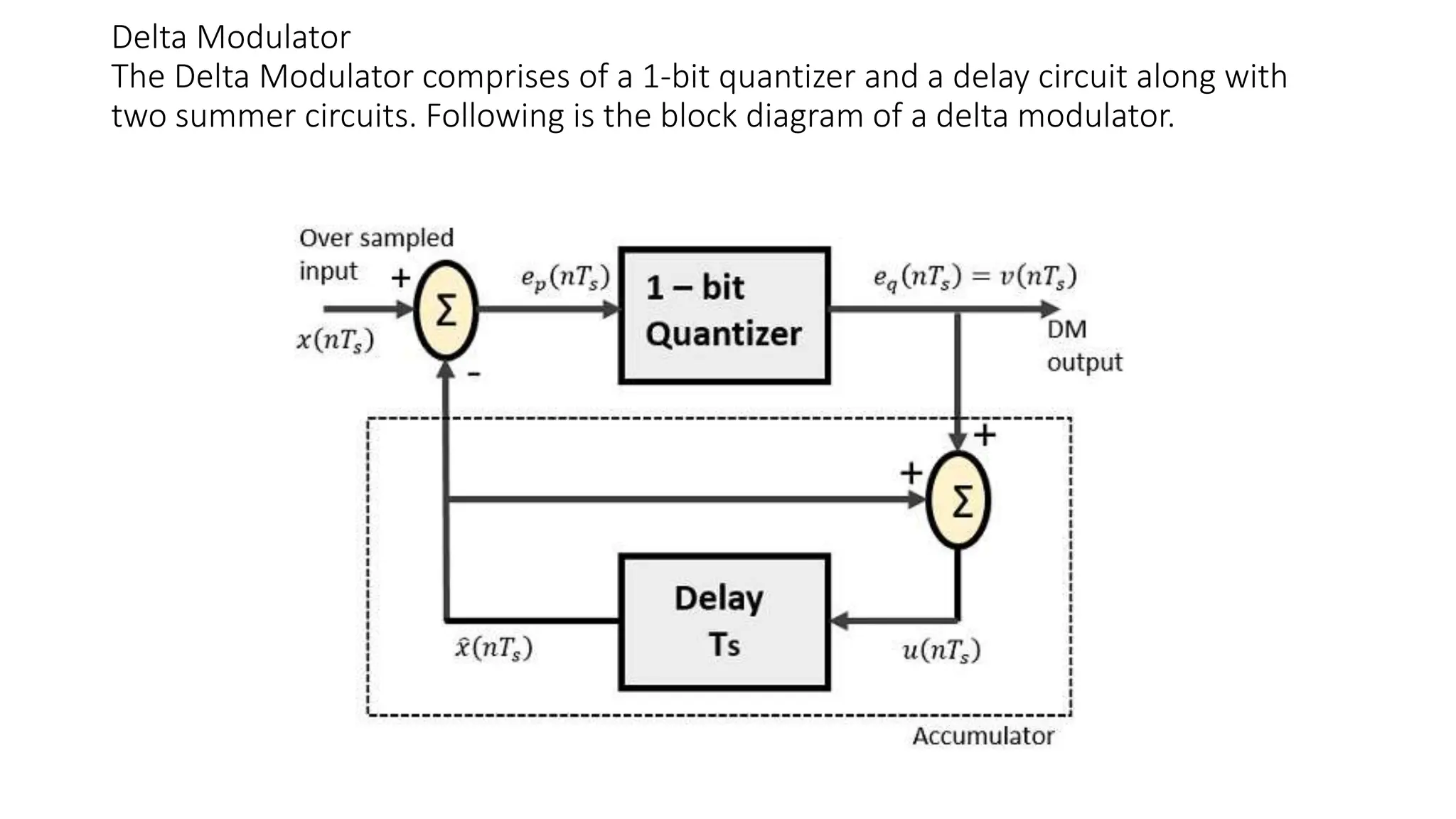
Non-Uniform Quantisation
Fig.shows a continuous time signal x(t) by dotted line. This
signal is sampled by flat top sampling at intervals Ts , 2Ts ,
3Ts ….. nTs .
• The sampling frequency is selected to be higher than nyquist rate.
• The samples are encoded by using 3 bit (7 levels) PCM.
• The sample is quantized to the nearest digital level as shown by small circles in fig .
• The encoded binary value of each sample is written on the top of the samples.
• We can observe from fig.1 that the samples taken at 4Ts , 5Ts and 6Ts are encoded
to same value of (110).
• This information can be carried only by one sample.
• But three smaples are carrying the same information means that it is redundant .
• We consider another example of samples taken at 9Ts and 10Ts.
• The difference between these samples only due to last bit and first two bits are
redundant, as they do not change.
• If this redundancy is reduced, then overall bit rate will decrease and number
of bits required to transmit one sample will also be reduced.
• This type of digital pulse modulation technique is called as
Differential Code Modulation (DPCM).
Should
Should
Should
Time
Delta Modulation:
The type of modulation, where the sampling rate is much higher and in
which the stepsize after quantization is of a smaller value Δ, such a
modulation is termed as delta modulation.
Features of Delta Modulation
Following are some of the features of delta modulation.
•An over-sampled input is taken to make full use of the signal correlation.
•The quantization design is simple.
•The input sequence is much higher than the Nyquist rate.
•The quality is moderate.
•The design of the modulator and the demodulator is simple.
•The stair-case approximation of output waveform.
•The step-size is very small, i.e., Δ deltadelta.
•The bit rate can be decided by the user.
•This involves simpler implementation.
Delta Modulator
The Delta Modulator comprises of a 1-bit quantizer and a delay circuit along with
two summer circuits. Following is the block diagram of a delta modulator.
Non-Uniform Quantisation in digital communication system

Non-Uniform Quantisation in digital communication system

  • 1.
  • 15.
    Fig.shows a continuoustime signal x(t) by dotted line. This signal is sampled by flat top sampling at intervals Ts , 2Ts , 3Ts ….. nTs .
  • 16.
    • The samplingfrequency is selected to be higher than nyquist rate. • The samples are encoded by using 3 bit (7 levels) PCM. • The sample is quantized to the nearest digital level as shown by small circles in fig . • The encoded binary value of each sample is written on the top of the samples. • We can observe from fig.1 that the samples taken at 4Ts , 5Ts and 6Ts are encoded to same value of (110). • This information can be carried only by one sample. • But three smaples are carrying the same information means that it is redundant . • We consider another example of samples taken at 9Ts and 10Ts. • The difference between these samples only due to last bit and first two bits are redundant, as they do not change. • If this redundancy is reduced, then overall bit rate will decrease and number of bits required to transmit one sample will also be reduced. • This type of digital pulse modulation technique is called as Differential Code Modulation (DPCM).
  • 17.
  • 19.
  • 20.
  • 25.
    Delta Modulation: The typeof modulation, where the sampling rate is much higher and in which the stepsize after quantization is of a smaller value Δ, such a modulation is termed as delta modulation. Features of Delta Modulation Following are some of the features of delta modulation. •An over-sampled input is taken to make full use of the signal correlation. •The quantization design is simple. •The input sequence is much higher than the Nyquist rate. •The quality is moderate. •The design of the modulator and the demodulator is simple. •The stair-case approximation of output waveform. •The step-size is very small, i.e., Δ deltadelta. •The bit rate can be decided by the user. •This involves simpler implementation.
  • 26.
    Delta Modulator The DeltaModulator comprises of a 1-bit quantizer and a delay circuit along with two summer circuits. Following is the block diagram of a delta modulator.