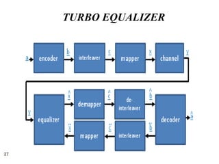
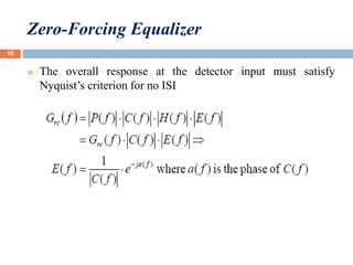
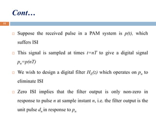
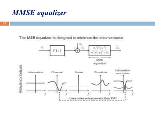
The document discusses adaptive linear equalizers and turbo equalizers. It provides an overview of how adaptive linear equalizers work to compensate for inter-symbol interference caused by time-variant channels. It also describes how turbo equalizers use feedback between an equalizer and decoder to iteratively improve signal estimation. Key components of the receiver like encoders, interleavers, mappers, and the forward-backward algorithm are explained. Applications of turbo equalization in technologies like SC-FDMA, GSM, and packet data transmission are also mentioned.

![Cont…
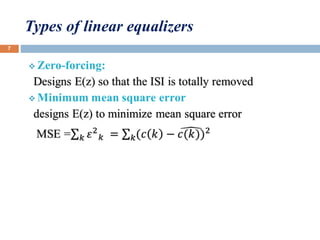
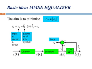
MMSE formulation
HE(z)
xn yn
an
- E[(.)2]
For a ‘fixed’ equaliser E[(.)2] is minimised by adjusting the
coefficients of HE(z). Effectively we have a trade off between
noise enhancement and ISI.
14](https://image.slidesharecdn.com/divyappt-161102111026/85/linear-equalizer-and-turbo-equalizer-14-320.jpg)