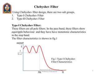
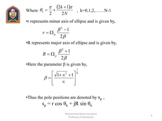
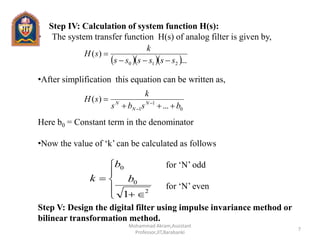
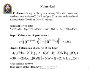
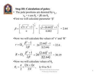
Using Chebyshev filter design, there are two sub groups,
Type-I Chebyshev Filter
Type-II Chebyshev Filter
The major difference between butterworth and chebyshev filter is that the poles of butterworth filter lie on the circle while the poles of chebyshev filter lie on ellipse.
2. Chebyshev Filter
ΩΩp
Using Chebyshev filter design, there are two sub groups,
1. Type-I Chebyshev Filter
2. Type-II Chebyshev Filter
Type-I Chebyshev Filter:
These filters are all pole filters. In the pass band, these filters show
equiripple behaviour and they have have monotonic characteristics
in the stop band.
The filter characteristics is shown in fig.1
IH(Ω)I2
1
2
1
1
Fig.1 Type-I Chebyshev
Filter Characteristics
2
Mohammad Akram,Assistant
Professor,JIT,Barabanki
3. • The magnitude squared frequency response of chebyshev filter is
given by:
Here = Chebyshev po;ynomial of order N.
ε = Ripple parameter in the passband
Type-II Chebyshev Filter:
• These filters contains zeros as well as poles.
• In the stop band, these filters show equiripple behaviour and they
have have monotonic characteristics in the pass band.
• The major difference between butterworth and chebyshev filter is
that the poles of butterworth filter lie on the circle while the poles of
chebyshev filter lie on ellipse.
P
NC
jH
22
2
1
1
p
NC
3
Mohammad Akram,Assistant
Professor,JIT,Barabanki
4. Chebyshev low pass filter design:
•Design equation and design steps:
Let A p=Attenuation in passband
As=Attenuation in stop band
Ωp=Passband edge frequency
Ωc=Cut off frequency
Ωs=Stopband edge frequency
Step I: Calculation of parameter ε :
It is given by :
If AP is not in dB then ε is calculated using the equation,
2
1
1.0
110
dBAP
2
1
2
1
1
AP
4
Mohammad Akram,Assistant
Professor,JIT,Barabanki
5. Step II: Calculation of order N of the filter:
•When stop band attenuation (As) is given in dB then ‘N’ is
calculated using the equation:
•When stop band attenuation (As) is not given in dB then ‘N’ is
calculated using the equation:
Step III: Calculation of poles:
•The position of poles of Chebyshev filter lie on ellipse at
coordinates x k and yk given by:
xk=r cos θk , k=0,1,2,…….N-1
yk=R sin θk , k=0,1,2,…….N-1
)(log20)1(6log20 1010 SS NNdBA
P
S
SA
N
1
5.0
2
1
cosh
1
11
cosh
5
Mohammad Akram,Assistant
Professor,JIT,Barabanki
6. Where , k=0,1,2,……N-1
•r represents minor axis of ellipse and is given by,
•R represents major axis of ellipse and is given by,
•Here the parameter β is given by,
•Thus the pole positions are denoted by sp ,
sp = r cos θk + jR sin θk
N
k
k
2
12
2
2
12
pr
2
12
pR
N
1
2
11
6
Mohammad Akram,Assistant
Professor,JIT,Barabanki
7. Step IV: Calculation of system function H(s):
• The system transfer function H(s) of analog filter is given by,
•After simplification this equation can be written as,
Here b0 = Constant term in the denominator
•Now the value of ‘k’ can be calculated as follows
for ‘N’ odd
for ‘N’ even
Step V: Design the digital filter using impulse invariance method or
bilinear transformation method.
...
)(
210 ssssss
k
sH
0
1
1 ...
)(
bsbs
k
sH N
N
N
2
0
0
1
b
b
k
7
Mohammad Akram,Assistant
Professor,JIT,Barabanki
8. Numerical
Problem-1:Design a Chebyshev analog filter with maximum
passband attenuation of 2.5 dB at Ωp = 20 rad/sec and stop band
attaenuation of 30 dB at Ωs = 50 rad/sec.
Solution: Given data:
Ap=2.5 db, Ωp = 20 rad/sec , As= 30 dB , Ωs = 50 rad/sec.
Step-I: Calculation of parameter ε :
= 0.882
Step II: Calculation of order N of the filter:
After solving, N=0.95
Thus order of the filter, N≈1
2
1
1.0
110
dBAP
2
1
)5.2(1.0
110
)(log20)1(6log20 1010 SS NNdBA
)50(log20)1(6882.0log2030 1010 NN
8
Mohammad Akram,Assistant
Professor,JIT,Barabanki
9. Step III: Calculation of poles:
• The pole positions are denoted by sp ,
sp = r cos θk + jR sin θk
•First we will calculate parameter ‘β’
= = 2.64
•Now we will calculate the values of ‘r’ and ‘R’
= = 22.6
= 30.19
•Now we will calculate values of θk
, k=0 to N-1
N
1
2
11
1
1
2
882.0
1882.01
2
12
pr
)64.2(2
164.2
20
2
2
12
pR
64.22
164.2
20
2
N
k
k
2
12
2
9
Mohammad Akram,Assistant
Professor,JIT,Barabanki
10.
12
102
2
0
= π
•Now we can write pole positions as
s0 = r cos θ0 + jR sin θ0 = 22.6 cos π + j (30.19) sin π = -22.6
Step IV: Calculation of system function H(s):
The system transfer function H(s) of analog filter is given by,
Here for N=1, we have
k= b0 = 22.6
This is the required transfer function.
0
)(
ss
k
sH
6.22
s
k
0
6.22
)(
ss
sH
10
Mohammad Akram,Assistant
Professor,JIT,Barabanki