Downloaded 110 times


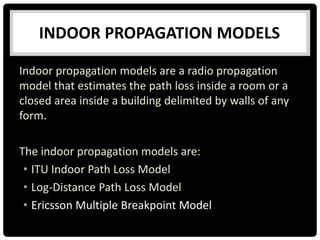
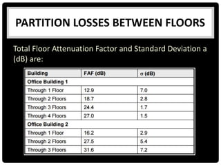
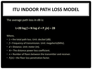
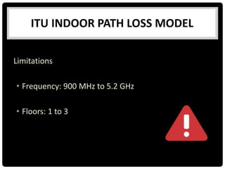
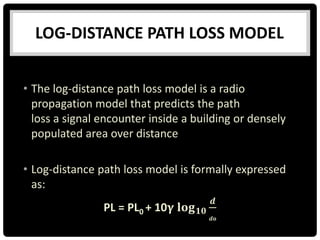
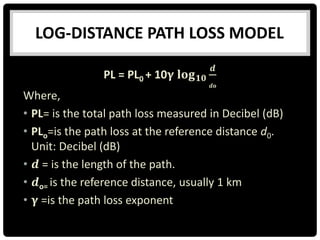
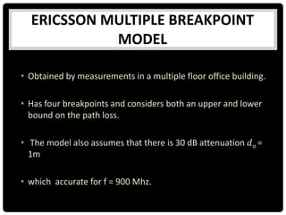
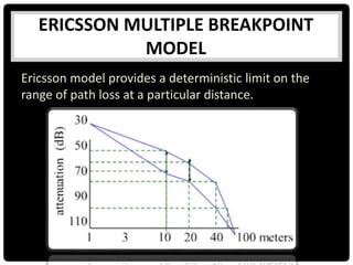


This document summarizes several indoor propagation models. It begins with introducing path loss factors like reflection, diffraction, and scattering. It then describes the ITU indoor path loss model, log-distance path loss model, and Ericsson multiple breakpoint model. The ITU model calculates path loss based on frequency, distance, and floor number. The log-distance model uses a path loss exponent to estimate loss over distance. The Ericsson model provides upper and lower loss bounds based on measurements in an office building.


![Getting Started with Apache Spark: Big Data Made Simple [Free Meetup]](https://cdn.slidesharecdn.com/ss_thumbnails/apachesparkgettingstarted-260203175547-8361bcc3-thumbnail.jpg?width=640&height=640&fit=bounds)


