Downloaded 17 times

![6
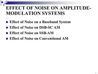
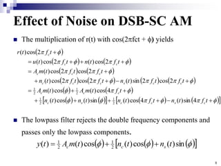
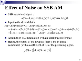
Effect of Noise on DSB-SC AM
Transmitted signal :
The received signal at the output of the receiver noise-
limiting filter : Sum of this signal and filtered noise
Recall from Section 5.3.3 and 2.7 that a filtered noise process
can be expressed in terms of its in-phase and quadrature
components as
(where nc(t) is in-phase component and ns(t) is quadrature
component)
t
f
t
m
A
t
u c
c
2
cos
)
(
)
(
)
2
sin(
)
(
)
2
cos(
)
(
)
2
sin(
)
(
sin
)
(
)
2
cos(
)
(
cos
)
(
)]
(
2
cos[
)
(
)
(
t
f
t
n
t
f
t
n
t
f
t
t
A
t
f
t
t
A
t
t
f
t
A
t
n
c
s
c
c
c
c
c
](https://image.slidesharecdn.com/noiseinamsystems-230221062143-fe9c0b8a/85/Noise-in-AM-systems-ppt-6-320.jpg)

![15
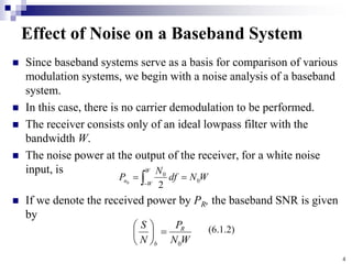
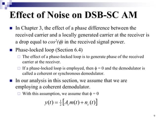
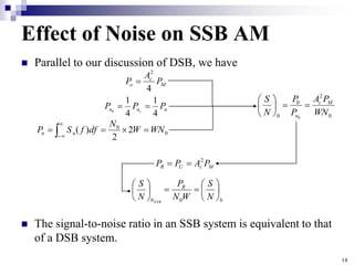
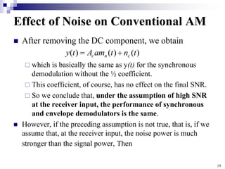
Effect of Noise on Conventional AM
DSB AM signal :
Received signal at the input to the demodulator
a is the modulation index
mn(t) is normalized so that its minimum value is -1
If a synchronous demodulator is employed, the situation is basically
similar to the DSB case, except that we have 1 + amn(t) instead of m(t).
After mixing and lowpass filtering
)
2
cos(
)]
(
1
[
)
( t
f
t
am
A
t
u c
n
c
t
f
t
n
t
f
t
n
t
am
A
t
f
t
n
t
f
t
n
t
f
t
am
A
t
n
t
f
t
am
A
t
r
c
s
c
c
n
c
c
s
c
c
c
n
c
c
n
c
2
sin
)
(
)
2
cos(
)
(
)]
(
1
[
2
sin
)
(
2
cos
)
(
)
2
cos(
)]
(
1
[
)
(
)
2
cos(
)]
(
1
[
)
(
)
(
)
(
)
( 2
1
t
n
t
am
A
t
y c
n
c
](https://image.slidesharecdn.com/noiseinamsystems-230221062143-fe9c0b8a/85/Noise-in-AM-systems-ppt-15-320.jpg)
![18
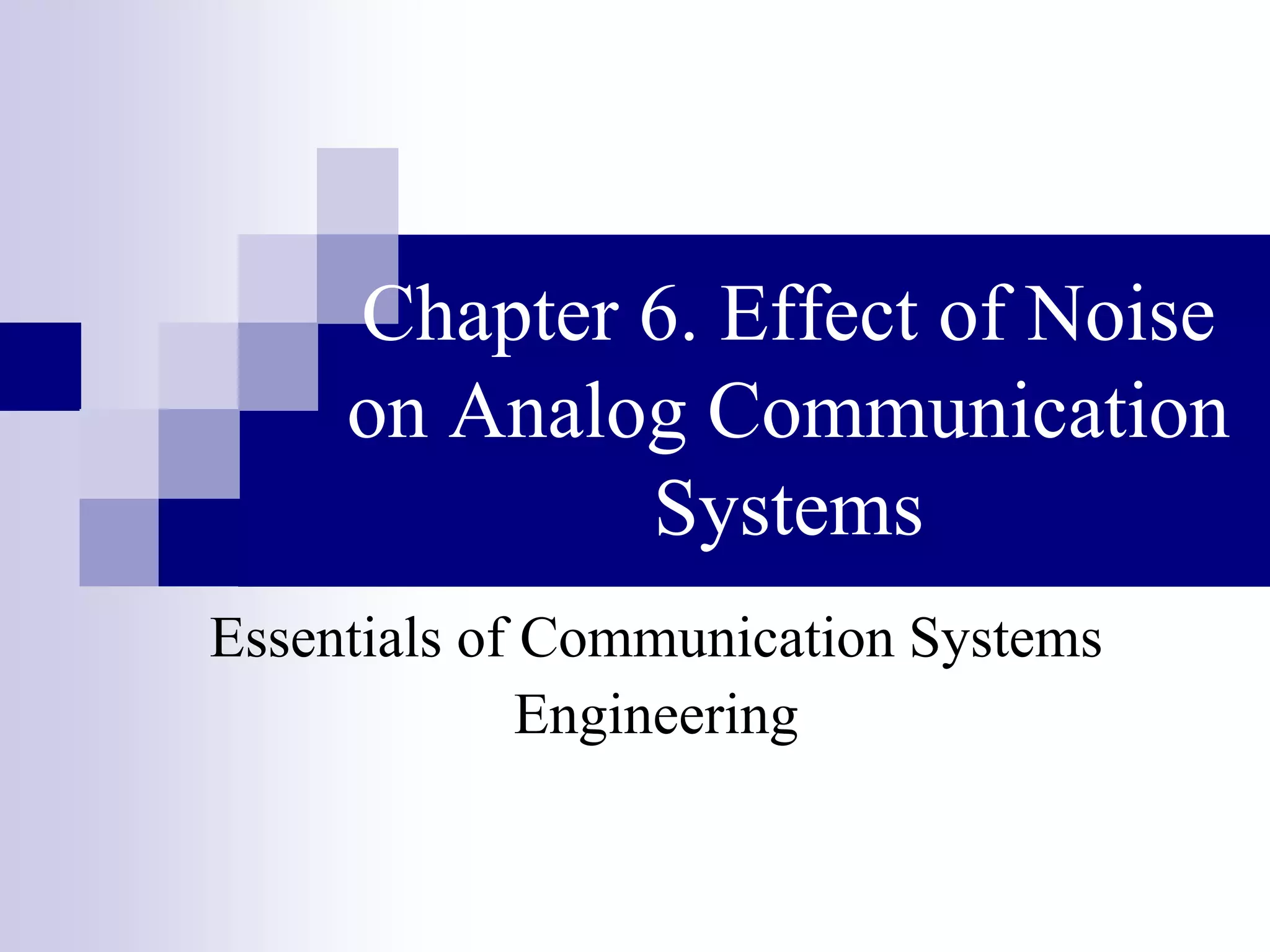
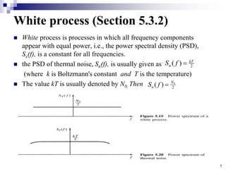
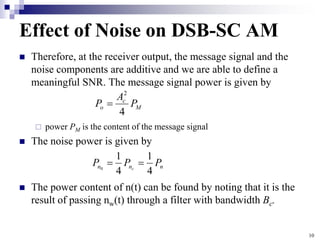
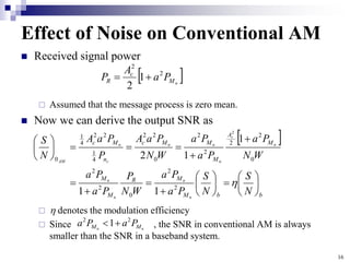
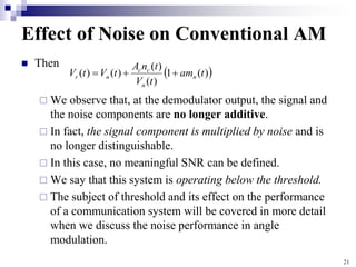
Effect of Noise on Conventional AM
In this case, the demodulator detects the envelope of the
received signal and the noise process.
The input to the envelope detector is
Therefore, the envelope of r ( t ) is given by
Now we assume that the signal component in r ( t ) is much
stronger than the noise component. Then
Therefore, we have a high probability that
t
f
t
n
t
f
t
n
t
am
A
t
r c
s
c
c
n
c
2
sin
)
(
)
2
cos(
)
(
)]
(
1
[
)
(
)
(
)
(
)]
(
1
[
)
( 2
2
t
n
t
n
t
am
A
t
V s
c
n
c
r
1
)]
(
1
[
)
(
t
am
A
t
n
P n
c
c
)
(
)]
(
1
[
)
( t
n
t
am
A
t
V c
n
c
r
](https://image.slidesharecdn.com/noiseinamsystems-230221062143-fe9c0b8a/85/Noise-in-AM-systems-ppt-18-320.jpg)
![20
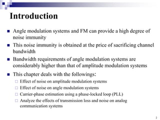
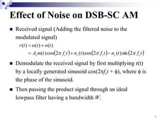
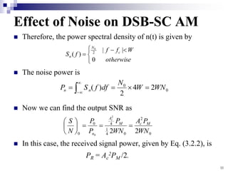
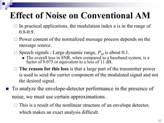
Effect of Noise on Conventional AM
(a) : is small compared with the other components
(b) : ;the envelope of the noise process
Use the approximation
, where
)
(
1
)
(
)
(
)
(
)
(
1
)
(
)
(
1
)
(
)
(
1
)
(
)
(
)
(
2
1
)
(
)
(
)]
(
1
)[
(
2
)
(
)
(
)]
(
1
[
)
(
)
(
)]
(
1
[
)
(
2
2
2
2
2
2
2
2
2
2
2
t
am
t
V
t
n
A
t
V
t
am
t
V
t
n
A
t
V
t
am
t
n
t
n
t
n
A
t
n
t
n
t
am
t
n
A
t
n
t
n
t
am
A
t
n
t
n
t
am
A
t
V
n
n
c
c
n
n
n
c
c
n
b
n
s
c
c
c
s
c
a
n
c
c
s
c
n
c
s
c
n
c
r
2
2
)]
(
1
[ t
am
A n
c
)
(
)
(
)
( 2
2
t
V
t
n
t
n n
s
c
small
for
,
1
1 2
)
(
1
)
(
)
(
)
(
2
2
2
t
am
t
n
t
n
t
n
A
n
s
c
c
c
](https://image.slidesharecdn.com/noiseinamsystems-230221062143-fe9c0b8a/85/Noise-in-AM-systems-ppt-20-320.jpg)

This chapter discusses the effect of noise on analog communication systems. It begins by introducing angle modulation systems and frequency modulation (FM), which can provide greater noise immunity than amplitude modulation (AM) systems, though they require more bandwidth. The chapter then examines the effects of noise on various AM systems, including double-sideband suppressed-carrier AM (DSB-SC AM), single-sideband AM (SSB AM), and conventional AM. It finds that DSB-SC AM and SSB AM do not provide any signal-to-noise ratio (SNR) improvement over a baseband system. The chapter also analyzes carrier phase estimation using a phase-locked loop and the effects of transmission loss and noise on analog communication systems