Downloaded 429 times
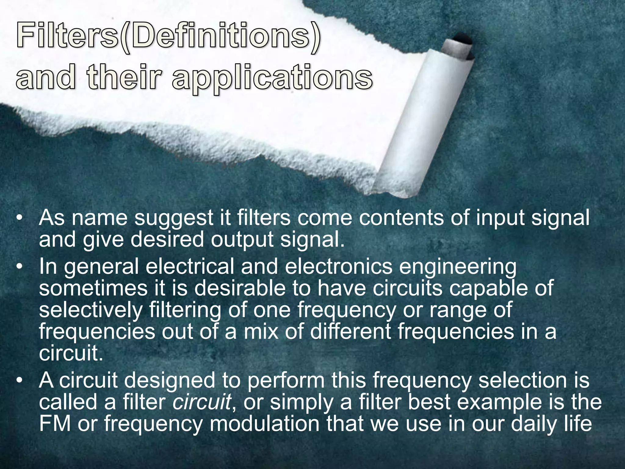
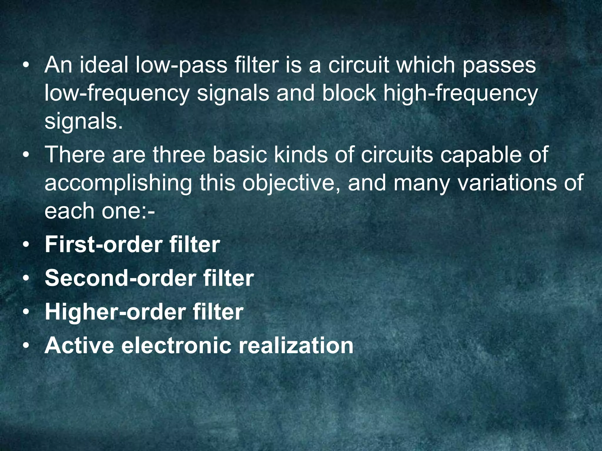
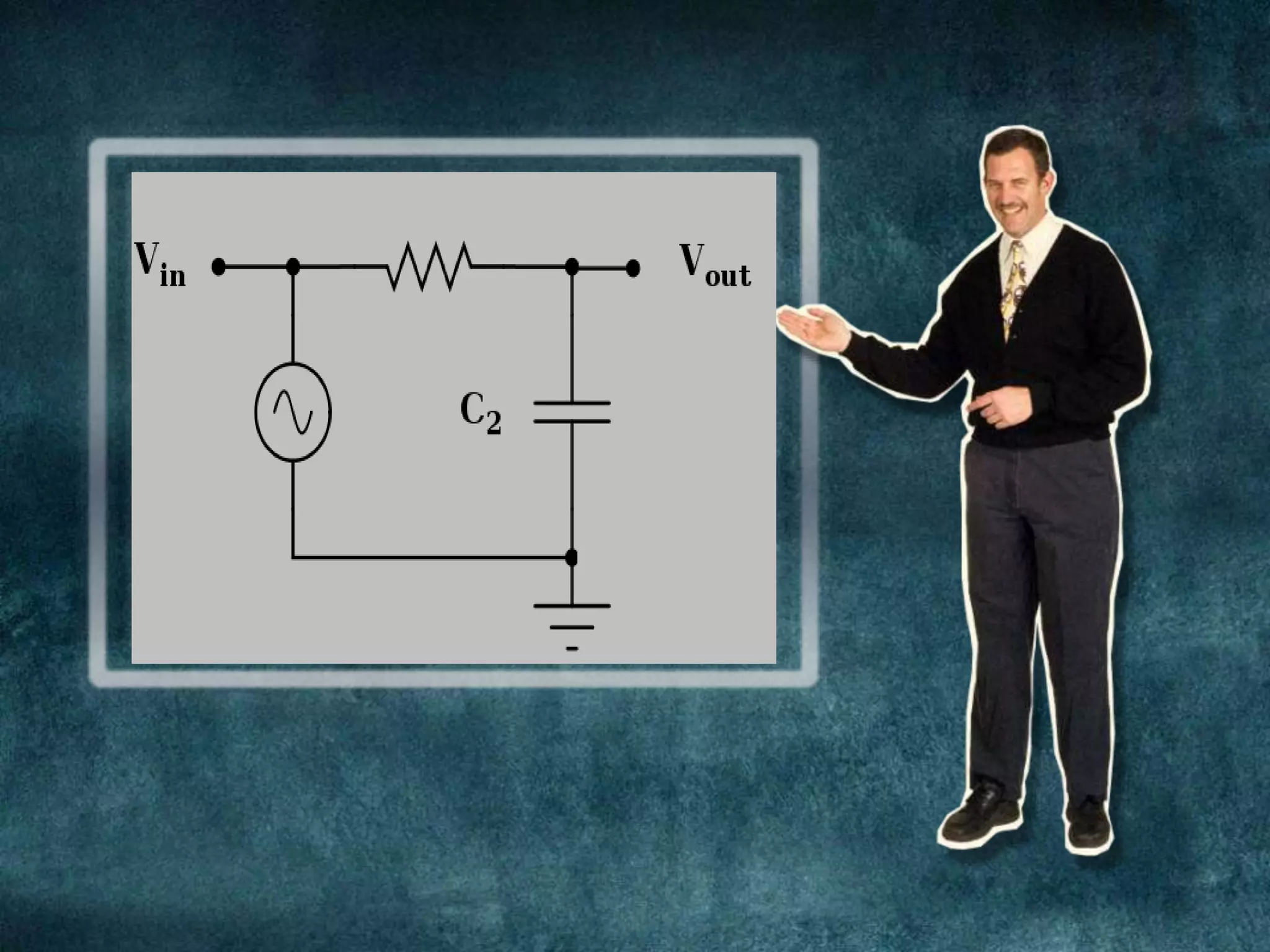
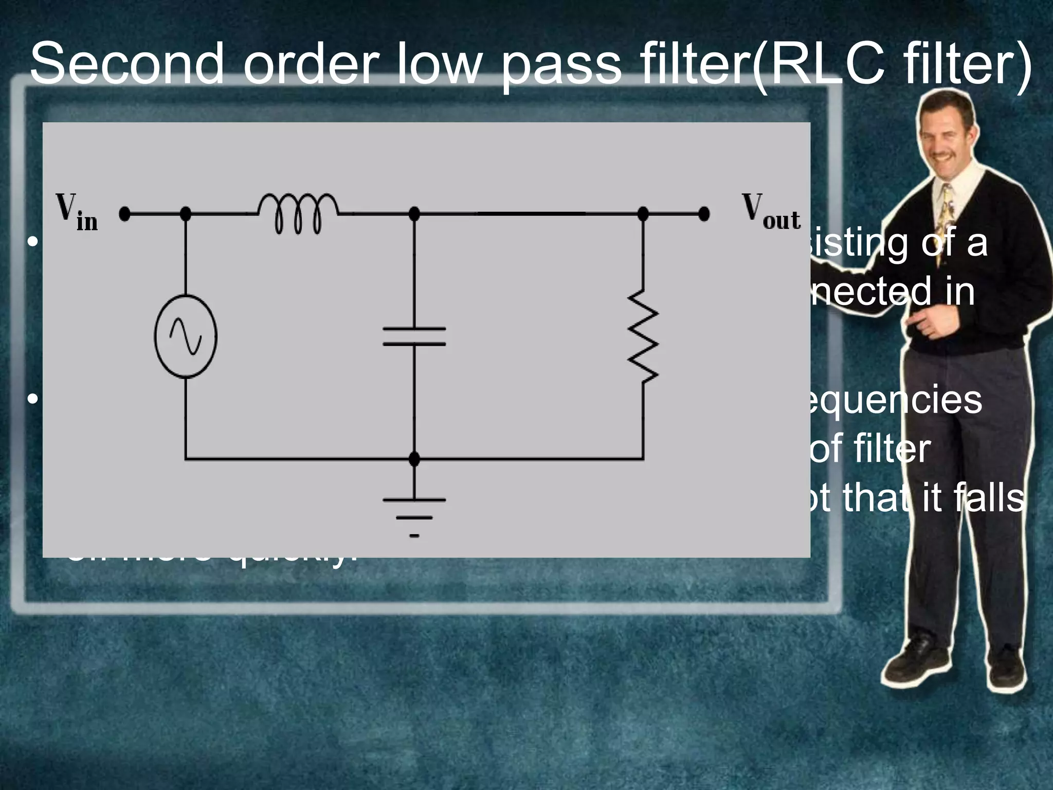
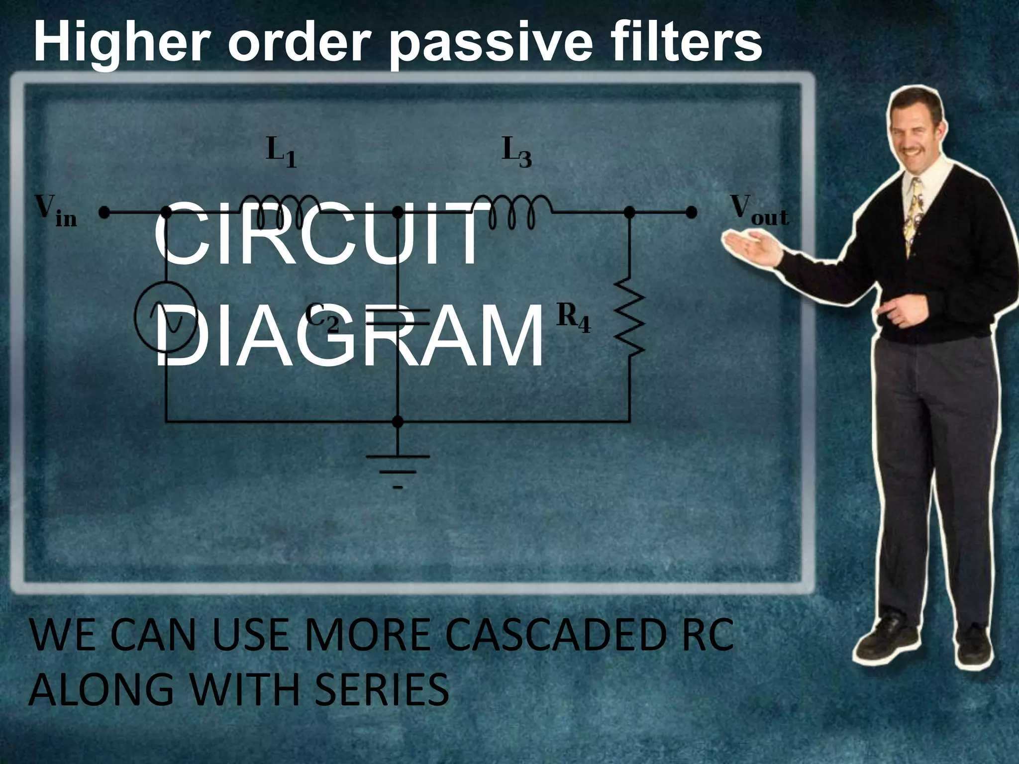
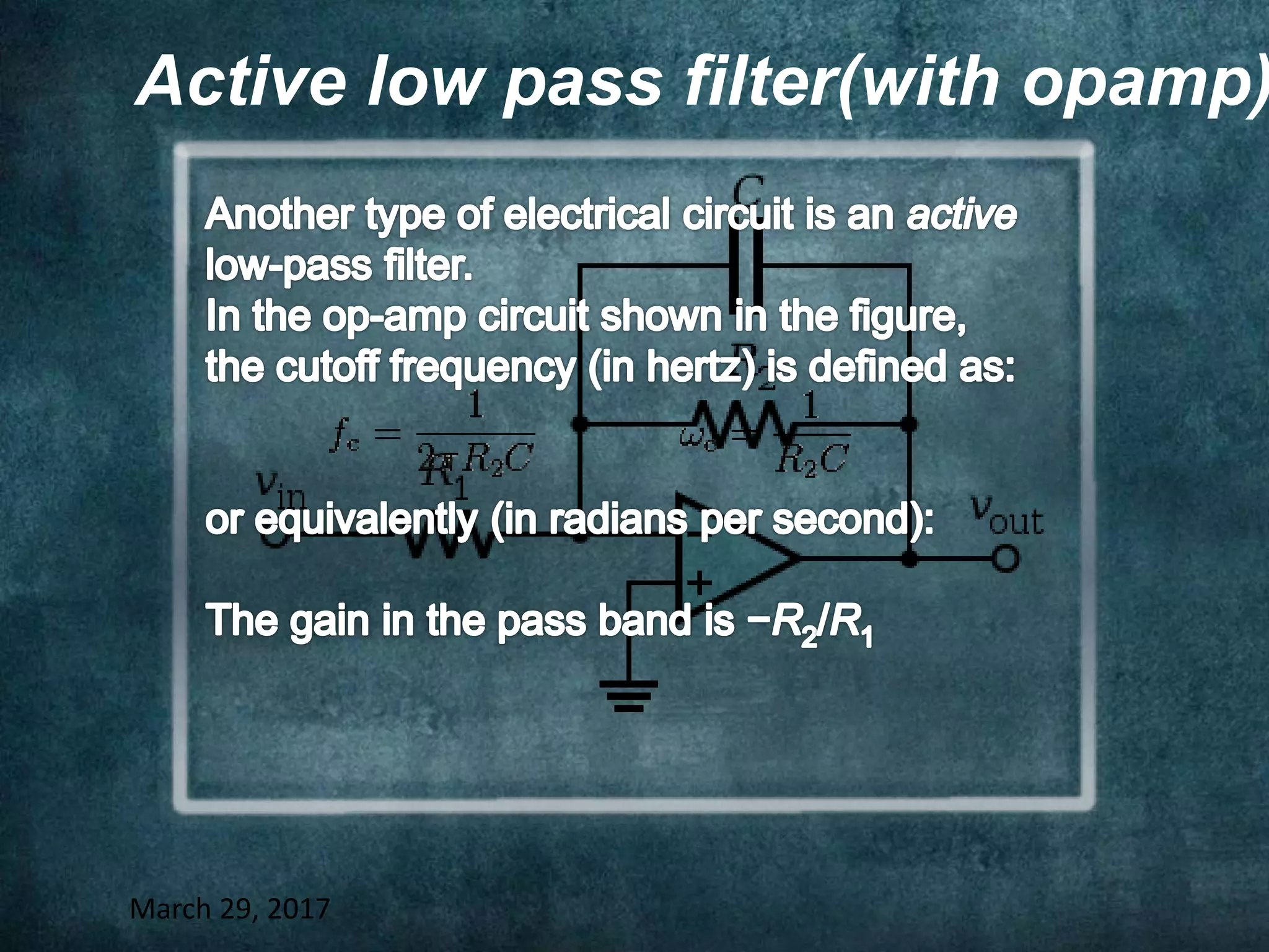


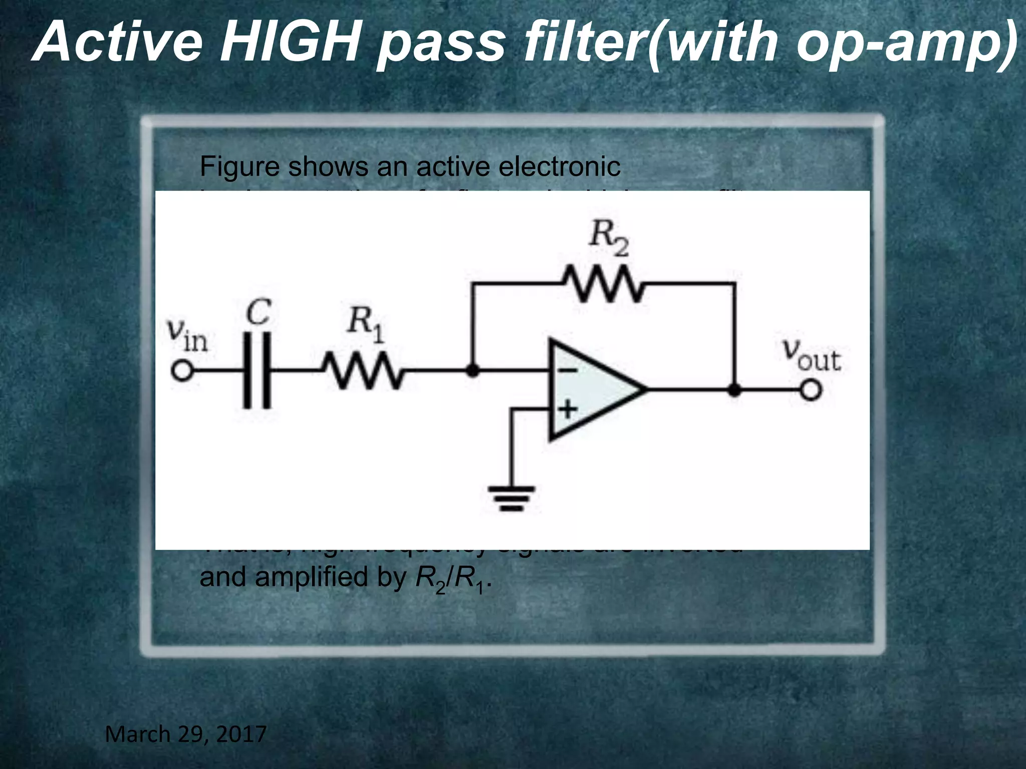
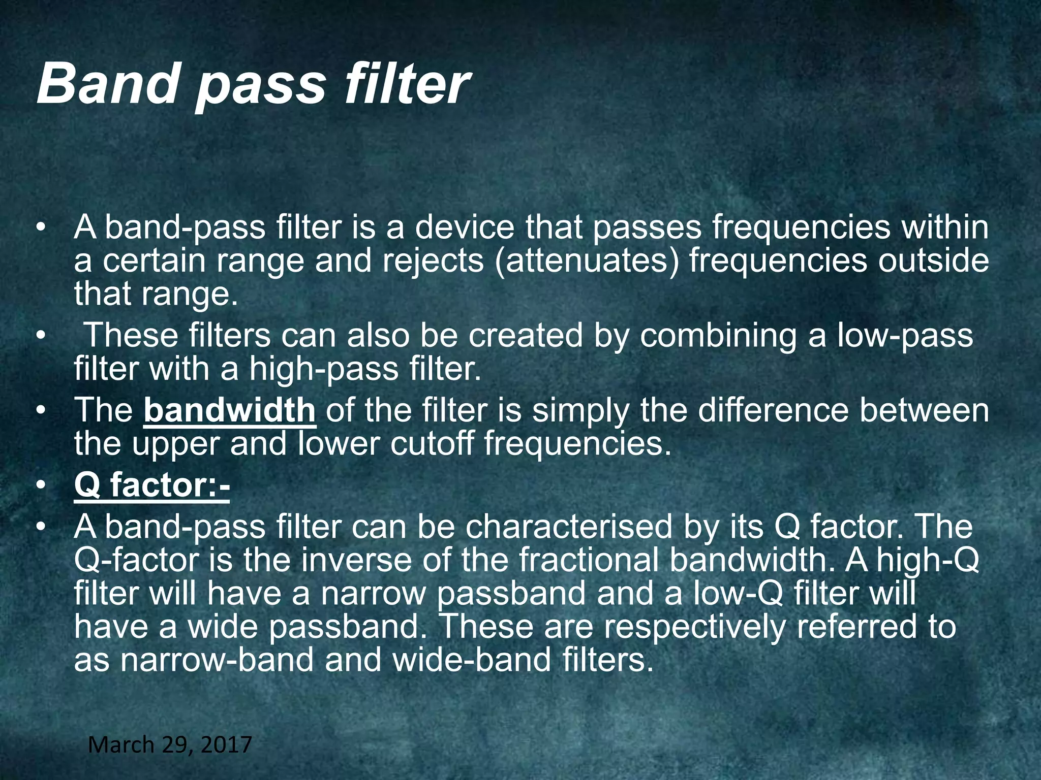
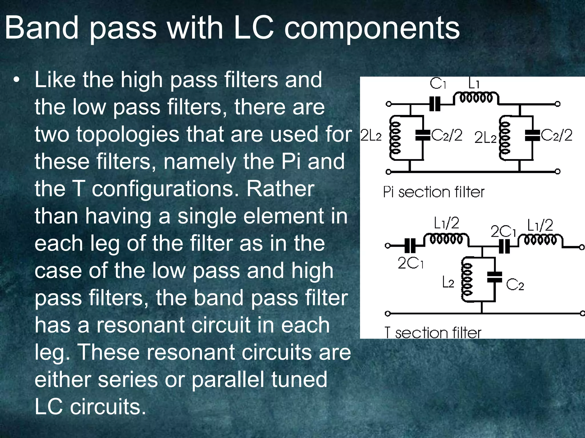
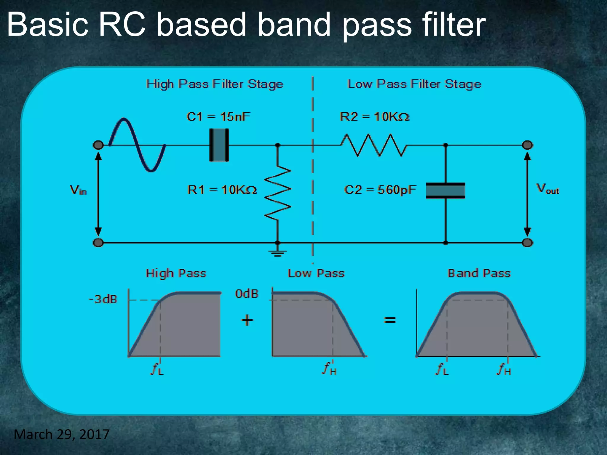

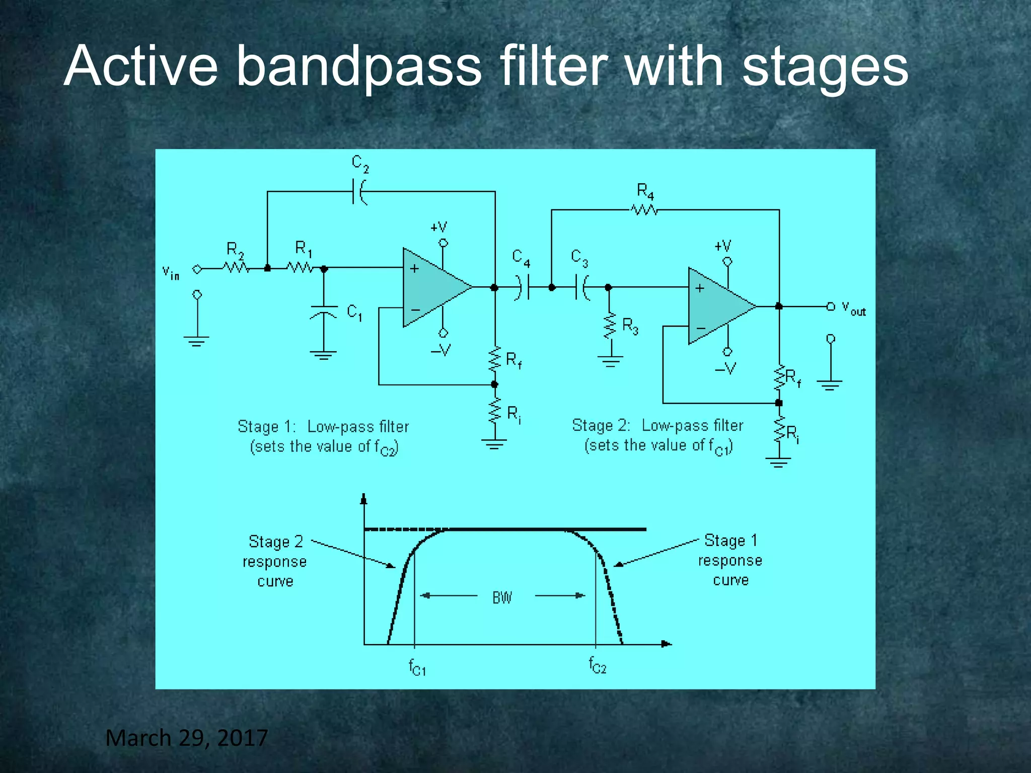
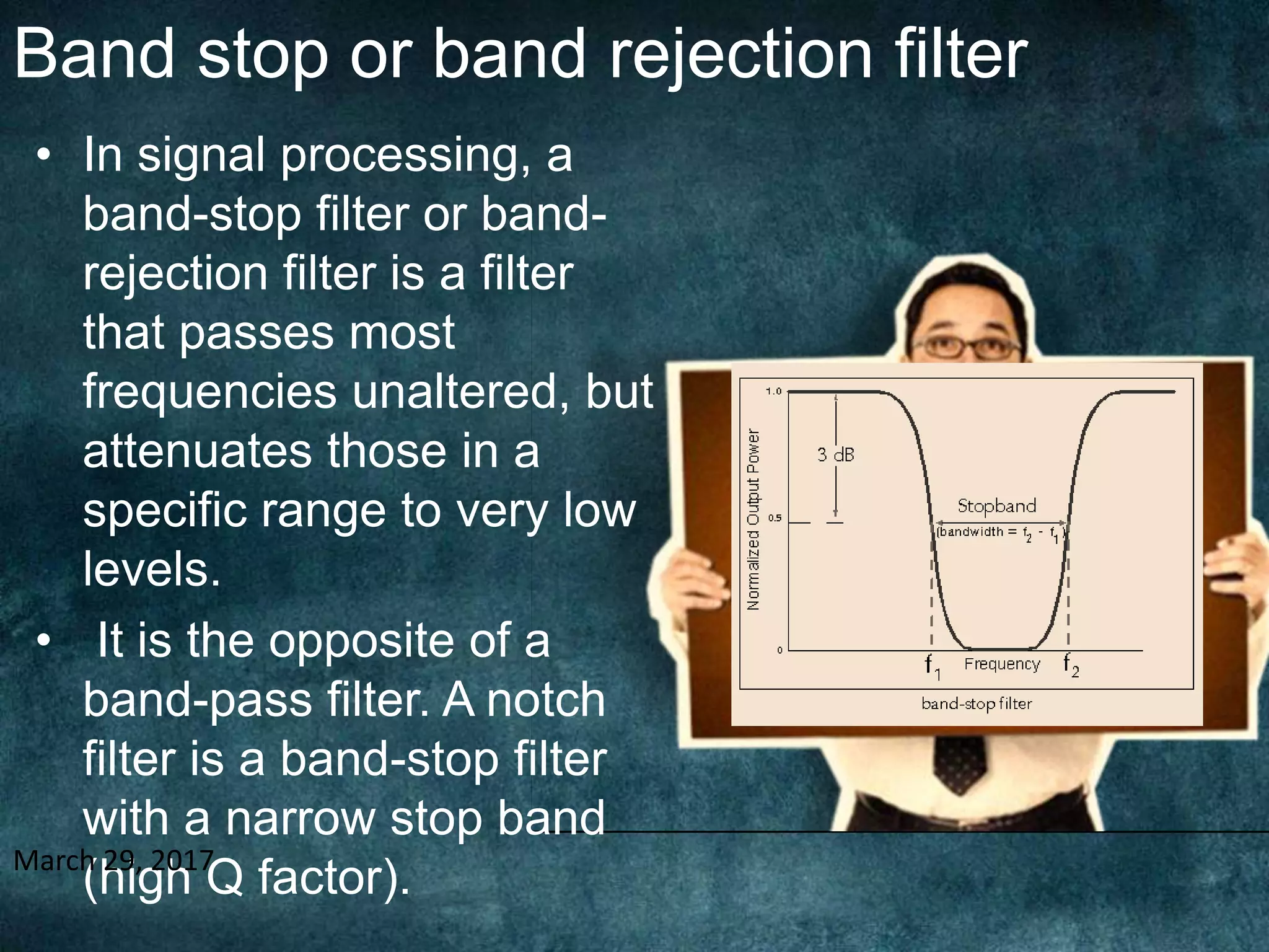


Filters are used to selectively pass or block ranges of frequencies in electronic circuits. The main types are low-pass filters, which pass low frequencies and block high frequencies; high-pass filters, which do the opposite; band-pass filters, which pass a band of frequencies; and band-stop or band-reject filters, which block a band of frequencies. Filters can be built using passive components like resistors, capacitors, and inductors in configurations like RC, RL, RLC, pi, and T networks or can use active components like op-amps. The document discusses examples and circuit diagrams of each main filter type.


![Lecture-6-[Passive Filter].pdfmmmmmmmmmmmmmmmmmmmm](https://cdn.slidesharecdn.com/ss_thumbnails/lecture-6-passivefilter-251130051517-4644d20e-thumbnail.jpg?width=640&height=640&fit=bounds)


