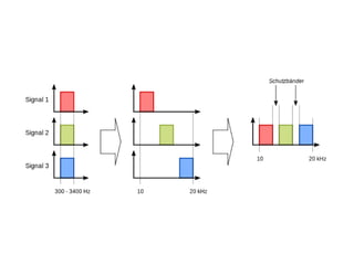
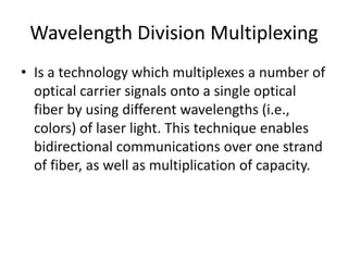
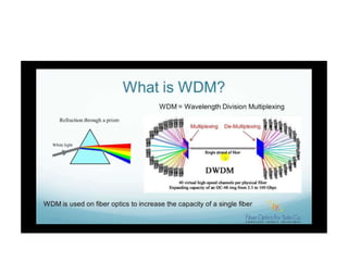
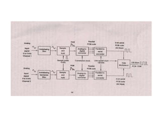
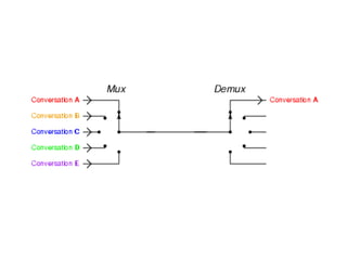
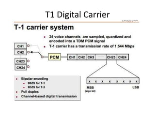
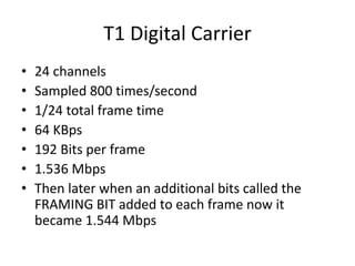
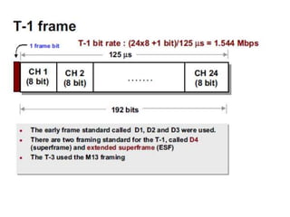
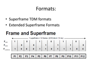
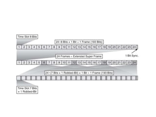
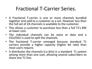
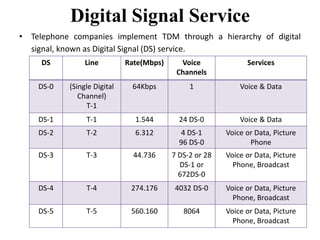
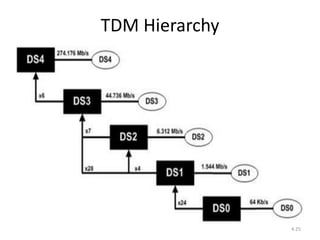
Digital T-Carriers and 
Multiplexing 
Group Reporters: 
Bugayong, laurens Luis L. 
Ramos, Romel R. 
Costiniano, Mariela 
Garcia, Gerald 
Alarcon, Mariel Klaudine V.
Introduction
Multiplexing. 
• Sometimes contracted to MUXING. 
• is a method by which multiple analog message 
signals or digital data streams are combined 
into one signal over a shared medium. 
• DEVICES THAT ARE USE FOR MULTIPLEXING: 
– Multiplexer (MUX), a device that perform a 
multiplexing 
– Demultiplexer (DEMUX), A device that perform 
the reverse function of the Multiplier.
Types of Multiplexing. 
• Space Division Multiplexing 
• Phase Division Multiplexing 
• Time Division Multiplexing 
• Frequency Division Multiplexing 
• Wavelength Division Multiplexing 
• Others.. 
– Polarization Division Multiplexing 
– Orbital Angular Momentum Multiplexing 
– Code Division Multiplexing
Space Division Multiplexing. 
• It implies different point-to-point wires for 
different channels. 
Examples:
Phase Division Multiplexing 
• It is a technique which allows two DSBSC 
(Double Sideband Suppressed carriers) 
channels sharing a common suppressed 
carrier to occupy the same spectrum space.
Frequency Division Multiplexing 
• Frequency-division multiplexing (FDM) is 
inherently an analog technology. FDM 
achieves the combining of several signals into 
one medium by sending signals in several 
distinct frequency ranges over a single 
medium.
Wavelength Division Multiplexing 
• Is a technology which multiplexes a number of 
optical carrier signals onto a single optical 
fiber by using different wavelengths (i.e., 
colors) of laser light. This technique enables 
bidirectional communications over one strand 
of fiber, as well as multiplication of capacity.
Time Division Multiplexing 
• technology which uses time, instead of space 
or frequency, to separate the different data 
streams.
T1 Digital Carrier
T1 Digital Carrier 
• 24 channels 
• Sampled 800 times/second 
• 1/24 total frame time 
• 64 KBps 
• 192 Bits per frame 
• 1.536 Mbps 
• Then later when an additional bits called the 
FRAMING BIT added to each frame now it 
became 1.544 Mbps
Channel Banks. 
• A channel bank is a device that converts analog 
signals into digital signals to be carried over 
higher-speed lines between the central office and 
other exchanges. The analog signal is converted 
into a digital signal that transmits at a rate of 64 
thousand bits per second ( Kbps ). This 64 Kbps 
signal is a standard known as a DS0 signal. The 
signal is multiplexed with other DS0 signals on 
the same line using time-division multiplexing ( 
TDM ) . Usually, the digital information is put on 
each DS0 signal using pulse code modulation ( 
PCM ).
Formats: 
• Superframe TDM formats 
• Extended Superframe Formats
Extended Superframes 
• It not only provide frame synchronization but also error detection and a data 
channel, all using the framing bit. 
• The value in every 193 bits (in bits 193, 386 & so on) are used for three purpose: 
1. Every 4th bit of this 24 bit cycle (i.e. the framing bits for frames 4,8,12,16,20 and 
24) goes through the pattern 001011.This provide frame synchronization. 
2. The framing bits for frames 2,6,10,……22 are used to send a 6 bit CRC, 
generated from the data in previous 24 frames. This provide “Error 
detection”. 
3. The Channel Service Units (CSU) can then track the error rate and generate an 
alarm if it gets too high. This error checking is done constantly while the links is 
in service and for any type of data. 
4. The remaining framing bits(for frames 1,3,5,7,….,23) provide a 4 kbps 
supervisory data channel that is used for other functions such as remote 
configuration and monitoring of CSU. 
5. The 8th bit in every channel of frames 6,12,18 & 24 is used for signaling 
between central offices.
Fractional T-Carrier Series. 
• A Fractional T-carrier is one or more channels bundled 
together and sold to a customer as a set. However less than 
the full set of 24 channels is available to the customer. 
• This allows a customer to purchase less than a full T1’s BW 
at lower cost. 
• The individual channels can be voice or data and a 
CSU/DSU is used to split the channels. 
• The fractional T-carrier emerged because standard T1 
carriers provide a higher capacity (higher bit rate) than 
most users require. 
• It distributes the channels (i.e bits) in a standard T1 system 
among more than one user, allowing several subscribers to 
share one T1 line.
• Bit rates offered with fractional T1-carrier 
system are 64 kbps(1-channel), 128 kbps(2- 
channels), 256 kbps(4-channels), 384 kbps(6- 
channels),512kbps(8-channels) and 768 
kbps(12-channels) with 384 kbps(1/4T1) and 
(1/2T1) being the most common. 
• The minimum required data rate required to 
propagate video information is 384 kbps.
Digital Signal Service 
• Telephone companies implement TDM through a hierarchy of digital 
signal, known as Digital Signal (DS) service. 
DS Line Rate(Mbps) Voice 
Channels 
Services 
DS-0 (Single Digital 
Channel) 
T-1 
64Kbps 1 Voice & Data 
DS-1 T-1 1.544 24 DS-0 Voice & Data 
DS-2 T-2 6.312 4 DS-1 
96 DS-0 
Voice or Data, Picture 
Phone 
DS-3 T-3 44.736 7 DS-2 or 28 
DS-1 or 
672DS-0 
Voice or Data, Picture 
Phone, Broadcast 
DS-4 T-4 274.176 4032 DS-0 Voice or Data, Picture 
Phone, Broadcast 
DS-5 T-5 560.160 8064 Voice or Data, Picture 
Phone, Broadcast
TDM Hierarchy 
4.25
MASTER GROUP & 
COMMERCIAL TELEVISION 
• The master group terminal receives voice band 
channels which are multiplexed using FDM. 
• The signal processor, shifts the master group signals 
frequencies, from a 564 KHz to 3084 KHz bandwidth 
to a 0 KHz to 2520 KHz BW. 
• DC restoration is also provided to TV signals. 
• The master group band is sampled at 5.1 MHz rate 
& for commercial TV signal sampling rate is 10.2 
MHz, i.e twice of master group rate. 
4.26
T3 Signal 
o/p 
(46 Mbps) 
Channel 
for TV 
(46 Mbps) 
Recove 1 
red 
Master 
Group 
Block Diagram of Master group & Commercial 
TV Digital Terminal 
4.27 
Signal 
Process 
or 
Encoder 
(9-bit) 
Sampl 
er 
Signal 
Process 
or 
& 
Sampler 
Digital 
Process 
or 
TV 
Cahnnel 
Mast 
er 
Grou 
p 
or 
TV 
Signa 
l 
Digital 
Process 
or 
Framer 
PAM 
Signa 
l 
12 
9 
T-3 
Signal 
Decode 
r 
(9-bit) 
2 
9 
Or 
TV 
Signal
• A 9-bit PCM code is used to digitize each sample of the master 
group or television signal. 
• The output of digital processor is approx 46 Mbps for master 
group and 92 Mbps for TV signal. 
As there is no 92 Mbps line speed in the digital hierarchy, the 
92 Mbps digital output must be split into two 46 Mbps signals 
for TV terminal. 
The digital terminal has three main functions: 
1. Conversion of the parallel data from the output of the 
encoder to the serial data. 
2. Frame synchronizing bits are inserted. 
3. It converts the serial binary signal to form more suitable for 
transmission. 
4.28
Picture Phone Terminal 
1. Used to transmit the low quality video signals for the 
use of non dedicated subscribers. 
2. This picture phone signal is encoded into T2 capacity 
of 6.312 Mbps, which is less than that for commercial 
network broadcast signals. 
3. Thus, reduced cost and affordability are achieved. 
4. It allows adequate details and contrast resolution to 
satisfy the average picture phone subscriber. 
5. Picture phone service is ideally suited to a DPCM. 
4.29
DATA TERMINAL 
• These are designed to transmit the signals other than voice. 
• In most of the cases, the data rate generated by each individual 
subscriber are substantially less than the data rate capacities of 
digital lines. 
• Therefore, it seems only logical that terminals be designed that 
transmit data signal from several sources over the same digital 
line. 
• Data coding method is more efficient & it codes the 
transition time . The coding format is as follows: 
1. It uses 3 bit code to indentify when transition occurs on the 
data and whether the transition is from ‘1’ to ‘0’ or vice versa. 
 First bit is referred as “Address bit”. 
 Second bit indicate “Transition bit” 
 Third bit indicate “Direction of transition or sign bit” 
4.30

Digital t carriers and multiplexing power point (laurens)

  • 1.
    Digital T-Carriers and Multiplexing Group Reporters: Bugayong, laurens Luis L. Ramos, Romel R. Costiniano, Mariela Garcia, Gerald Alarcon, Mariel Klaudine V.
  • 2.
  • 3.
    Multiplexing. • Sometimescontracted to MUXING. • is a method by which multiple analog message signals or digital data streams are combined into one signal over a shared medium. • DEVICES THAT ARE USE FOR MULTIPLEXING: – Multiplexer (MUX), a device that perform a multiplexing – Demultiplexer (DEMUX), A device that perform the reverse function of the Multiplier.
  • 4.
    Types of Multiplexing. • Space Division Multiplexing • Phase Division Multiplexing • Time Division Multiplexing • Frequency Division Multiplexing • Wavelength Division Multiplexing • Others.. – Polarization Division Multiplexing – Orbital Angular Momentum Multiplexing – Code Division Multiplexing
  • 5.
    Space Division Multiplexing. • It implies different point-to-point wires for different channels. Examples:
  • 6.
    Phase Division Multiplexing • It is a technique which allows two DSBSC (Double Sideband Suppressed carriers) channels sharing a common suppressed carrier to occupy the same spectrum space.
  • 7.
    Frequency Division Multiplexing • Frequency-division multiplexing (FDM) is inherently an analog technology. FDM achieves the combining of several signals into one medium by sending signals in several distinct frequency ranges over a single medium.
  • 9.
    Wavelength Division Multiplexing • Is a technology which multiplexes a number of optical carrier signals onto a single optical fiber by using different wavelengths (i.e., colors) of laser light. This technique enables bidirectional communications over one strand of fiber, as well as multiplication of capacity.
  • 11.
    Time Division Multiplexing • technology which uses time, instead of space or frequency, to separate the different data streams.
  • 14.
  • 15.
    T1 Digital Carrier • 24 channels • Sampled 800 times/second • 1/24 total frame time • 64 KBps • 192 Bits per frame • 1.536 Mbps • Then later when an additional bits called the FRAMING BIT added to each frame now it became 1.544 Mbps
  • 17.
    Channel Banks. •A channel bank is a device that converts analog signals into digital signals to be carried over higher-speed lines between the central office and other exchanges. The analog signal is converted into a digital signal that transmits at a rate of 64 thousand bits per second ( Kbps ). This 64 Kbps signal is a standard known as a DS0 signal. The signal is multiplexed with other DS0 signals on the same line using time-division multiplexing ( TDM ) . Usually, the digital information is put on each DS0 signal using pulse code modulation ( PCM ).
  • 18.
    Formats: • SuperframeTDM formats • Extended Superframe Formats
  • 19.
    Extended Superframes •It not only provide frame synchronization but also error detection and a data channel, all using the framing bit. • The value in every 193 bits (in bits 193, 386 & so on) are used for three purpose: 1. Every 4th bit of this 24 bit cycle (i.e. the framing bits for frames 4,8,12,16,20 and 24) goes through the pattern 001011.This provide frame synchronization. 2. The framing bits for frames 2,6,10,……22 are used to send a 6 bit CRC, generated from the data in previous 24 frames. This provide “Error detection”. 3. The Channel Service Units (CSU) can then track the error rate and generate an alarm if it gets too high. This error checking is done constantly while the links is in service and for any type of data. 4. The remaining framing bits(for frames 1,3,5,7,….,23) provide a 4 kbps supervisory data channel that is used for other functions such as remote configuration and monitoring of CSU. 5. The 8th bit in every channel of frames 6,12,18 & 24 is used for signaling between central offices.
  • 21.
    Fractional T-Carrier Series. • A Fractional T-carrier is one or more channels bundled together and sold to a customer as a set. However less than the full set of 24 channels is available to the customer. • This allows a customer to purchase less than a full T1’s BW at lower cost. • The individual channels can be voice or data and a CSU/DSU is used to split the channels. • The fractional T-carrier emerged because standard T1 carriers provide a higher capacity (higher bit rate) than most users require. • It distributes the channels (i.e bits) in a standard T1 system among more than one user, allowing several subscribers to share one T1 line.
  • 22.
    • Bit ratesoffered with fractional T1-carrier system are 64 kbps(1-channel), 128 kbps(2- channels), 256 kbps(4-channels), 384 kbps(6- channels),512kbps(8-channels) and 768 kbps(12-channels) with 384 kbps(1/4T1) and (1/2T1) being the most common. • The minimum required data rate required to propagate video information is 384 kbps.
  • 24.
    Digital Signal Service • Telephone companies implement TDM through a hierarchy of digital signal, known as Digital Signal (DS) service. DS Line Rate(Mbps) Voice Channels Services DS-0 (Single Digital Channel) T-1 64Kbps 1 Voice & Data DS-1 T-1 1.544 24 DS-0 Voice & Data DS-2 T-2 6.312 4 DS-1 96 DS-0 Voice or Data, Picture Phone DS-3 T-3 44.736 7 DS-2 or 28 DS-1 or 672DS-0 Voice or Data, Picture Phone, Broadcast DS-4 T-4 274.176 4032 DS-0 Voice or Data, Picture Phone, Broadcast DS-5 T-5 560.160 8064 Voice or Data, Picture Phone, Broadcast
  • 25.
  • 26.
    MASTER GROUP & COMMERCIAL TELEVISION • The master group terminal receives voice band channels which are multiplexed using FDM. • The signal processor, shifts the master group signals frequencies, from a 564 KHz to 3084 KHz bandwidth to a 0 KHz to 2520 KHz BW. • DC restoration is also provided to TV signals. • The master group band is sampled at 5.1 MHz rate & for commercial TV signal sampling rate is 10.2 MHz, i.e twice of master group rate. 4.26
  • 27.
    T3 Signal o/p (46 Mbps) Channel for TV (46 Mbps) Recove 1 red Master Group Block Diagram of Master group & Commercial TV Digital Terminal 4.27 Signal Process or Encoder (9-bit) Sampl er Signal Process or & Sampler Digital Process or TV Cahnnel Mast er Grou p or TV Signa l Digital Process or Framer PAM Signa l 12 9 T-3 Signal Decode r (9-bit) 2 9 Or TV Signal
  • 28.
    • A 9-bitPCM code is used to digitize each sample of the master group or television signal. • The output of digital processor is approx 46 Mbps for master group and 92 Mbps for TV signal. As there is no 92 Mbps line speed in the digital hierarchy, the 92 Mbps digital output must be split into two 46 Mbps signals for TV terminal. The digital terminal has three main functions: 1. Conversion of the parallel data from the output of the encoder to the serial data. 2. Frame synchronizing bits are inserted. 3. It converts the serial binary signal to form more suitable for transmission. 4.28
  • 29.
    Picture Phone Terminal 1. Used to transmit the low quality video signals for the use of non dedicated subscribers. 2. This picture phone signal is encoded into T2 capacity of 6.312 Mbps, which is less than that for commercial network broadcast signals. 3. Thus, reduced cost and affordability are achieved. 4. It allows adequate details and contrast resolution to satisfy the average picture phone subscriber. 5. Picture phone service is ideally suited to a DPCM. 4.29
  • 30.
    DATA TERMINAL •These are designed to transmit the signals other than voice. • In most of the cases, the data rate generated by each individual subscriber are substantially less than the data rate capacities of digital lines. • Therefore, it seems only logical that terminals be designed that transmit data signal from several sources over the same digital line. • Data coding method is more efficient & it codes the transition time . The coding format is as follows: 1. It uses 3 bit code to indentify when transition occurs on the data and whether the transition is from ‘1’ to ‘0’ or vice versa.  First bit is referred as “Address bit”.  Second bit indicate “Transition bit”  Third bit indicate “Direction of transition or sign bit” 4.30