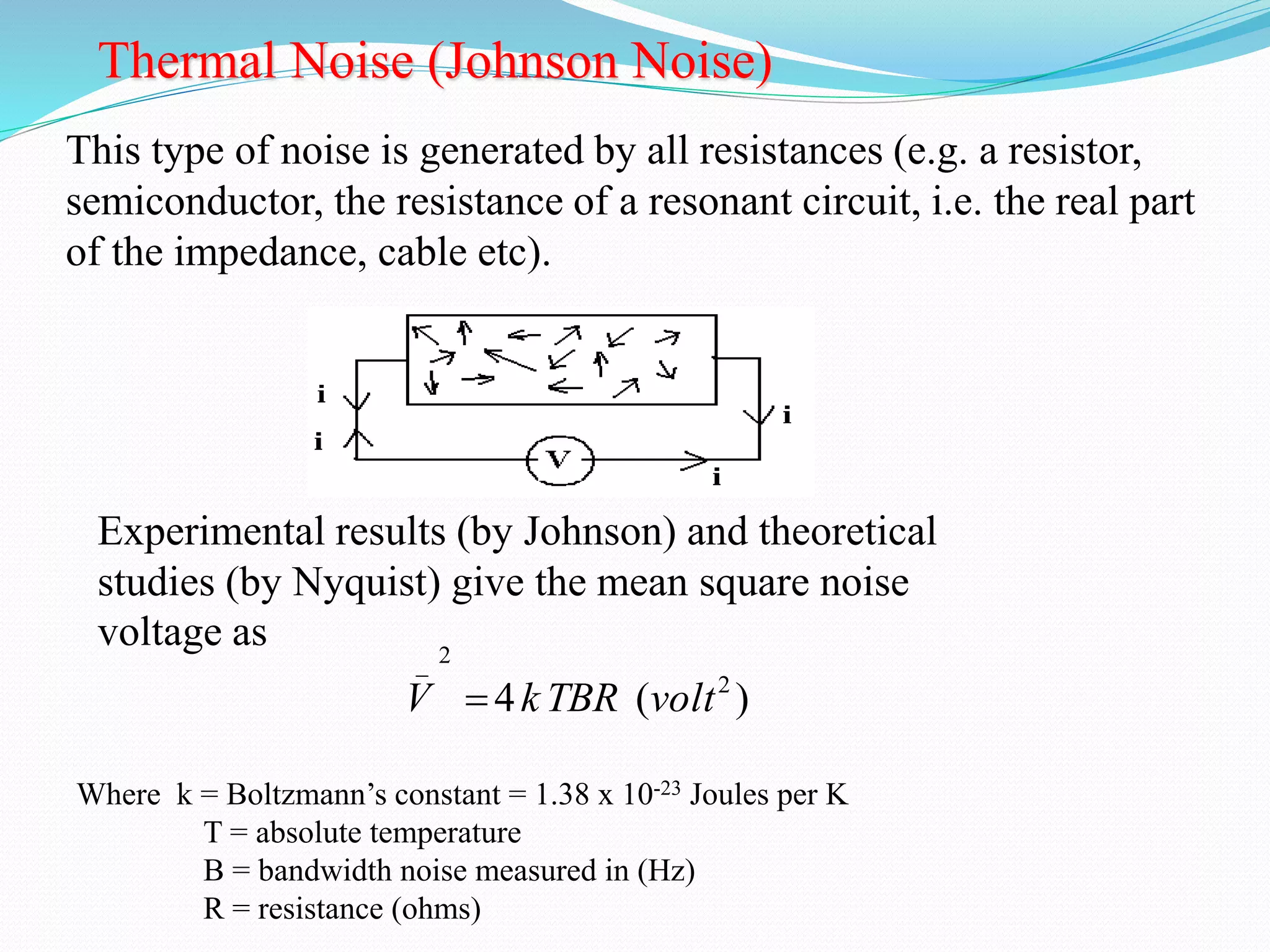
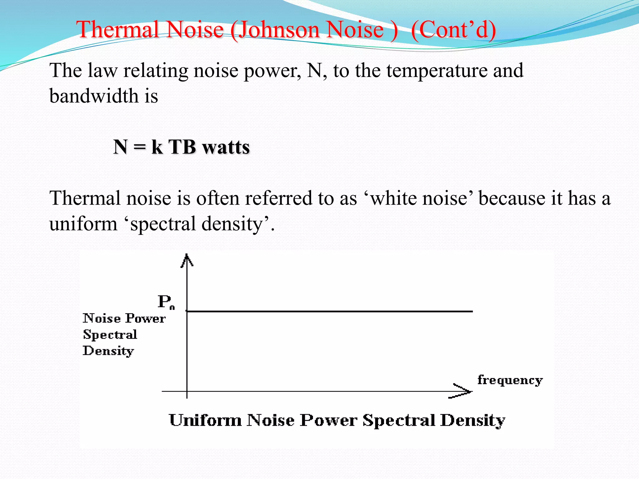
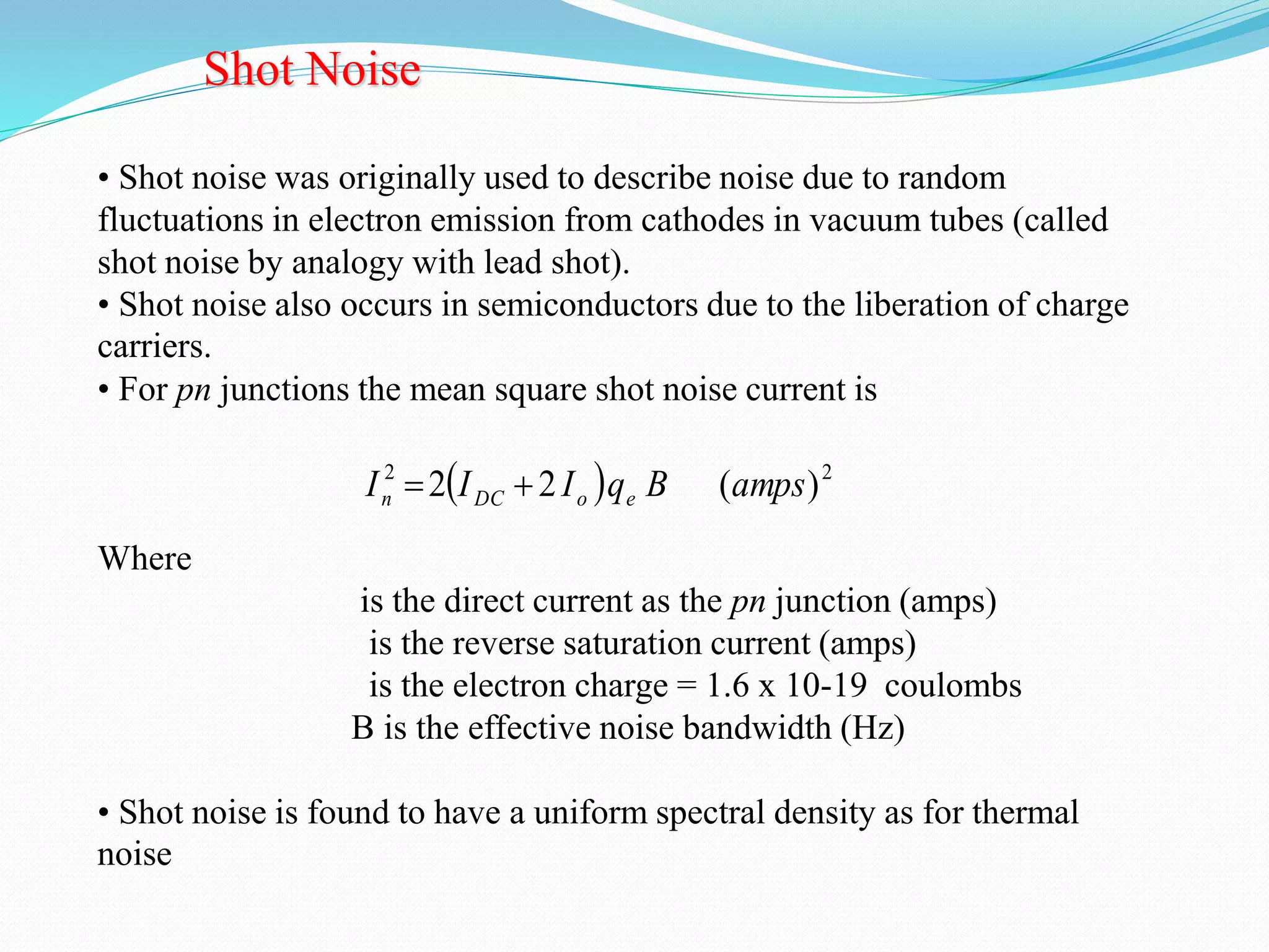
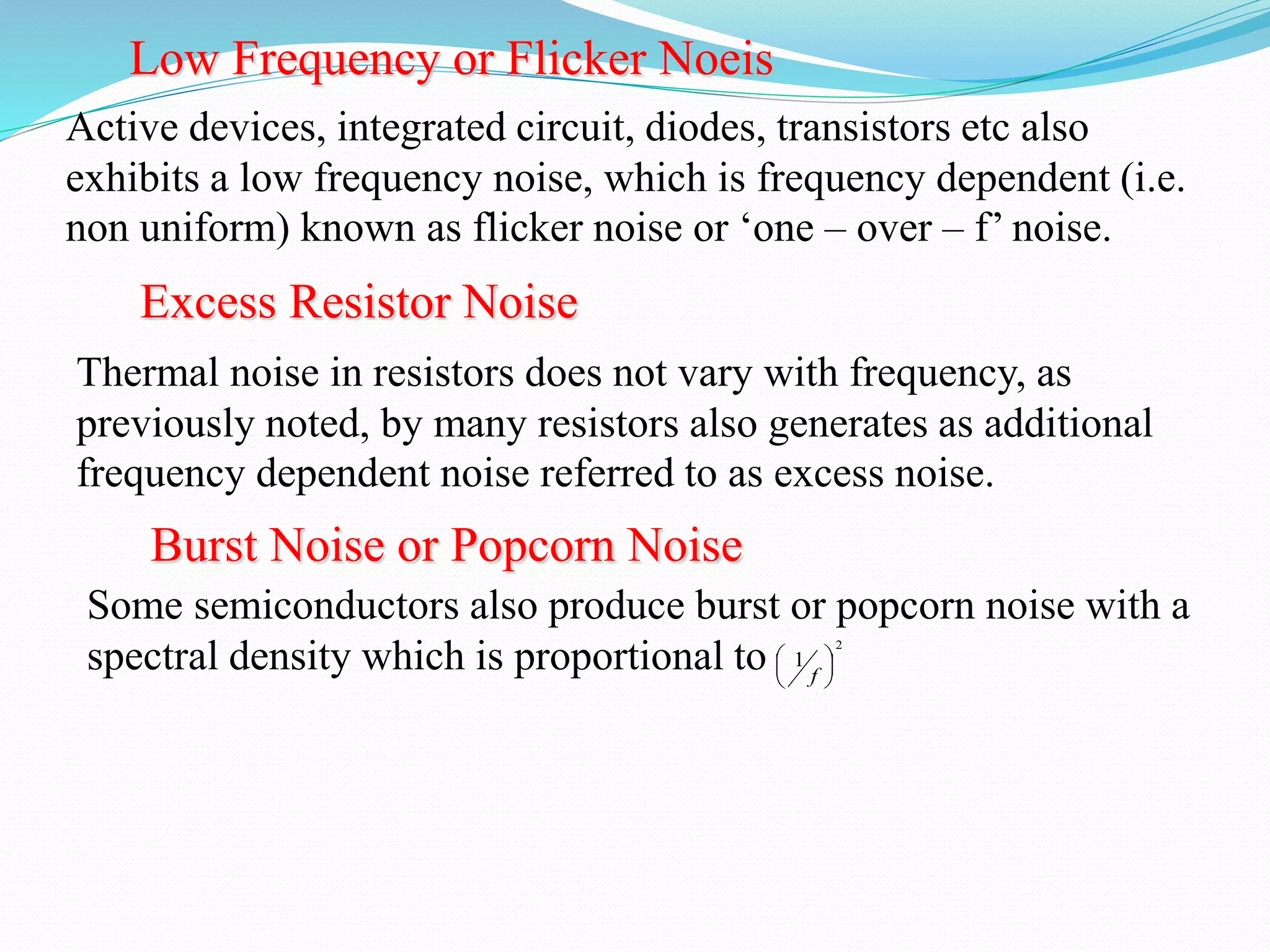
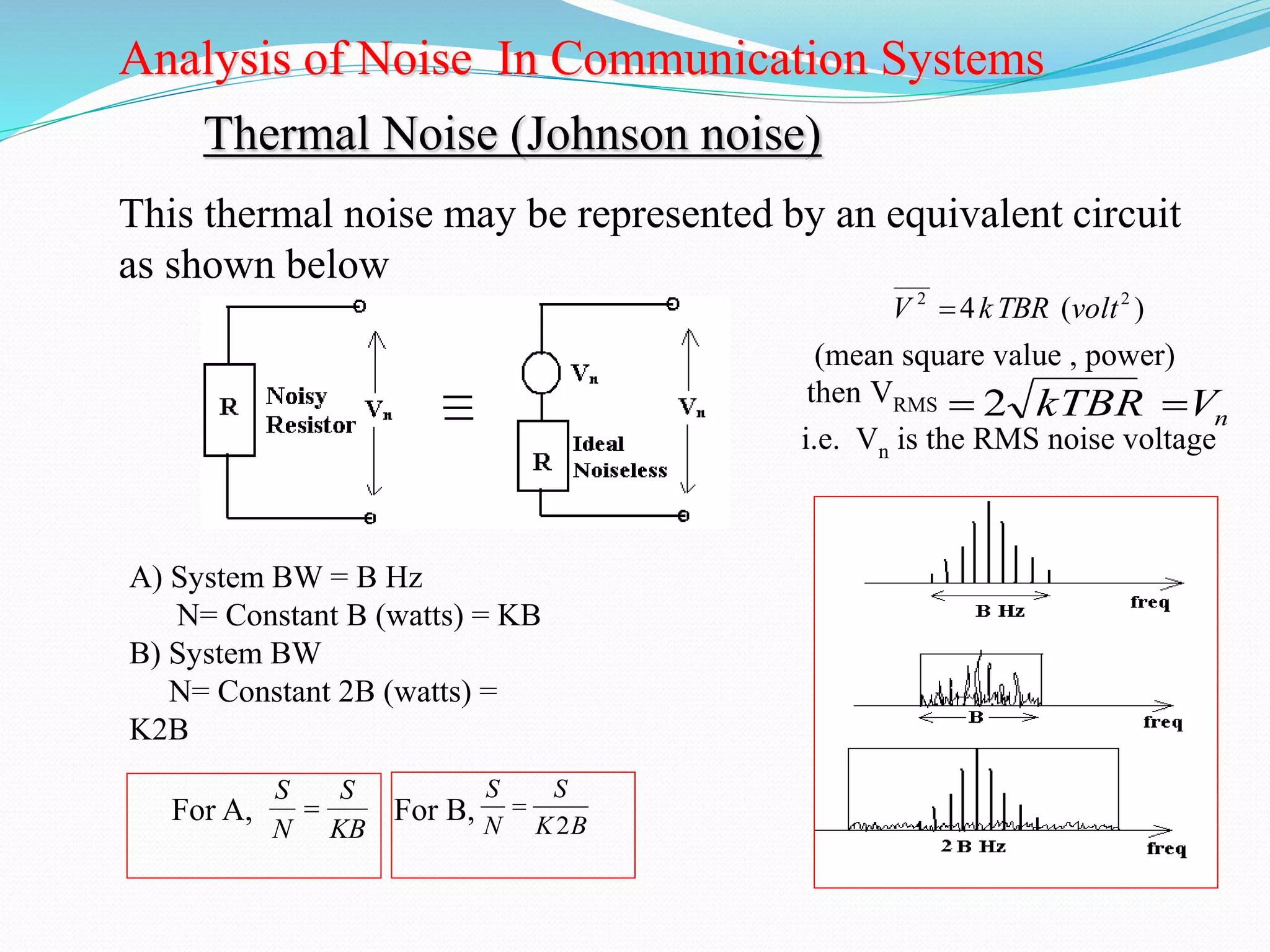
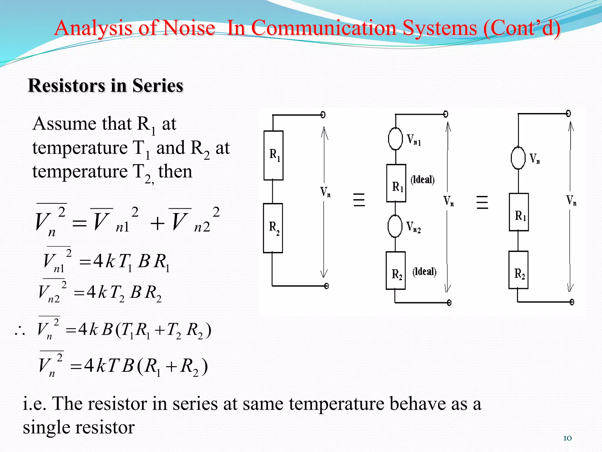
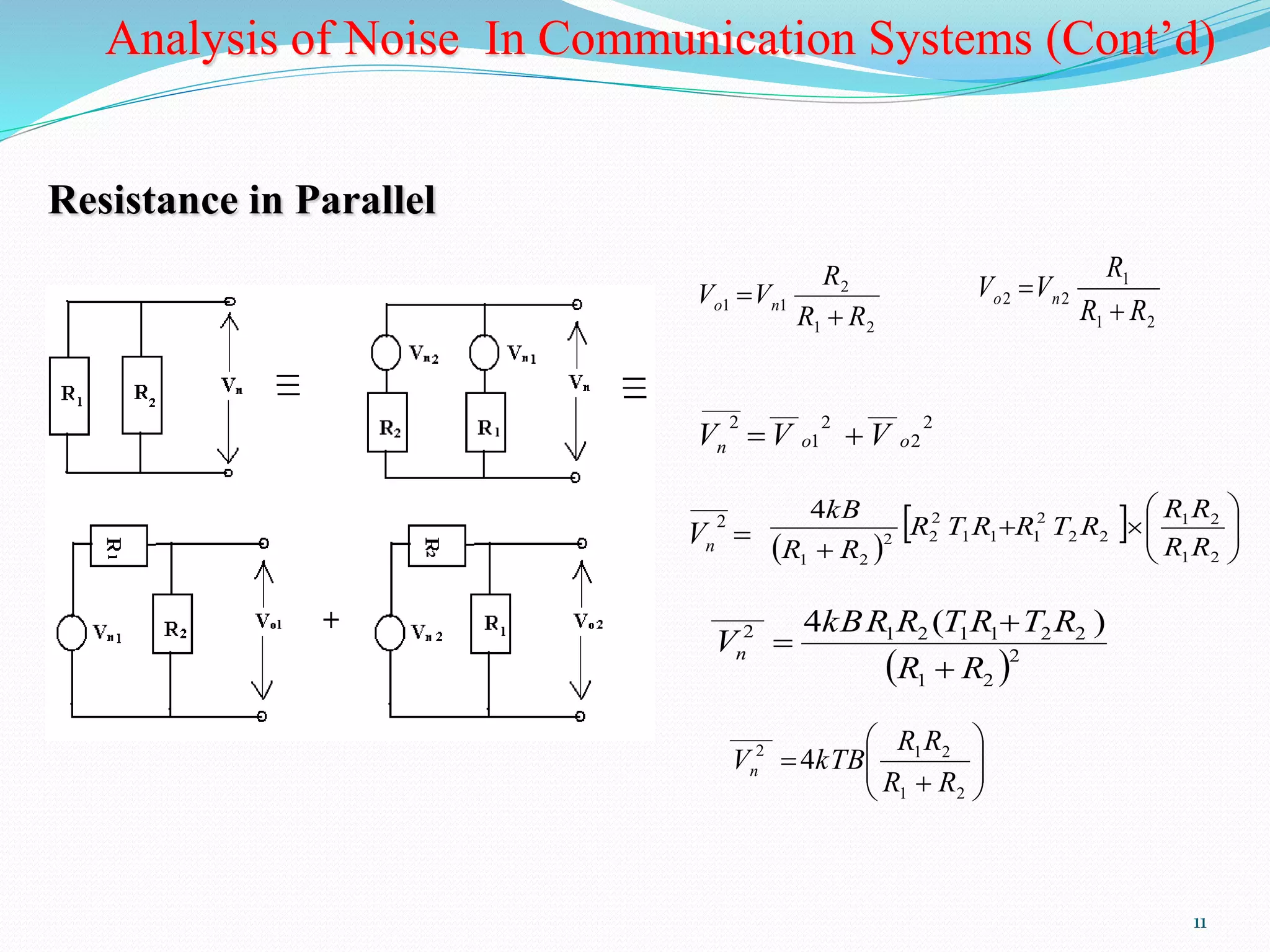
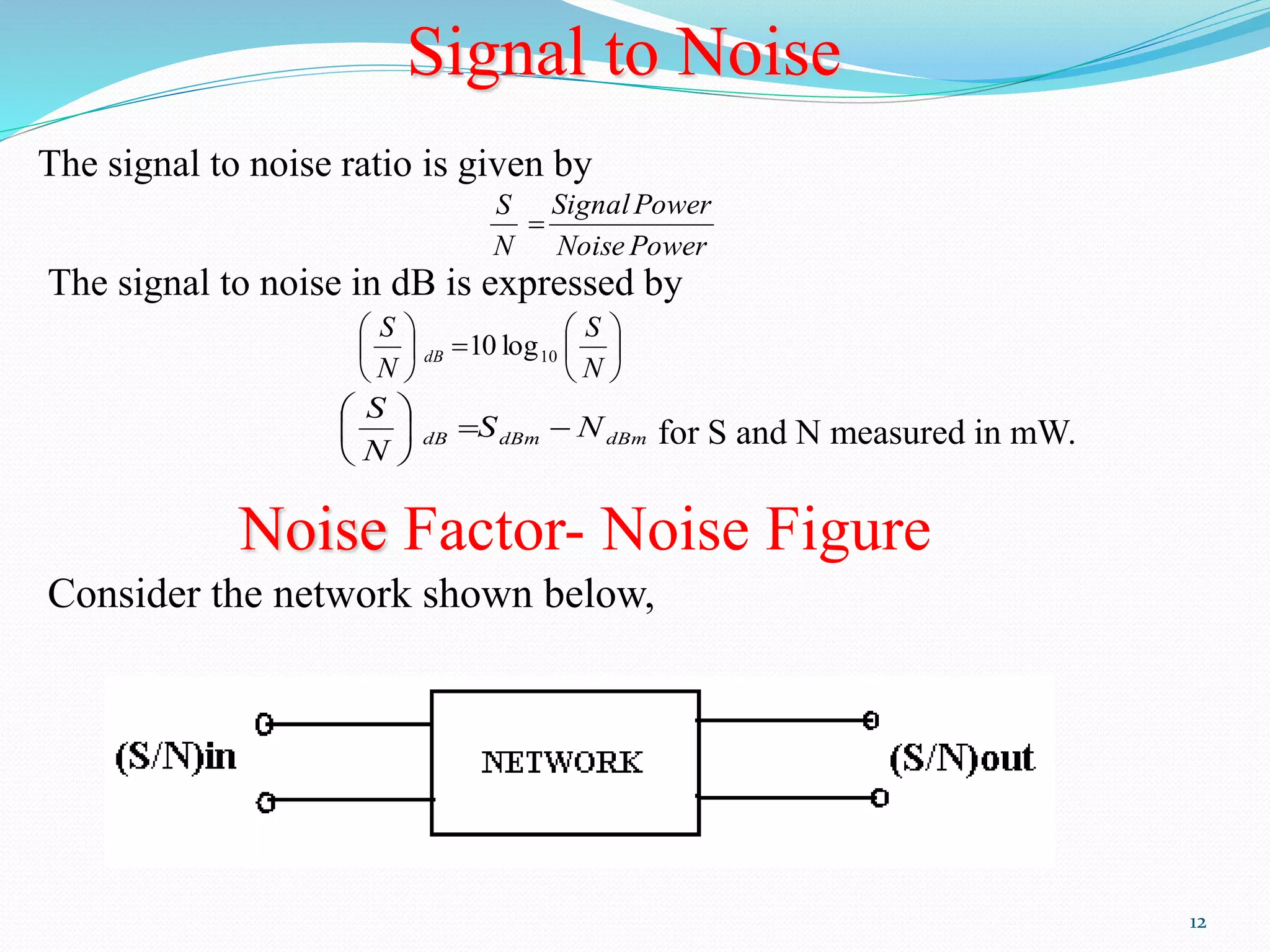
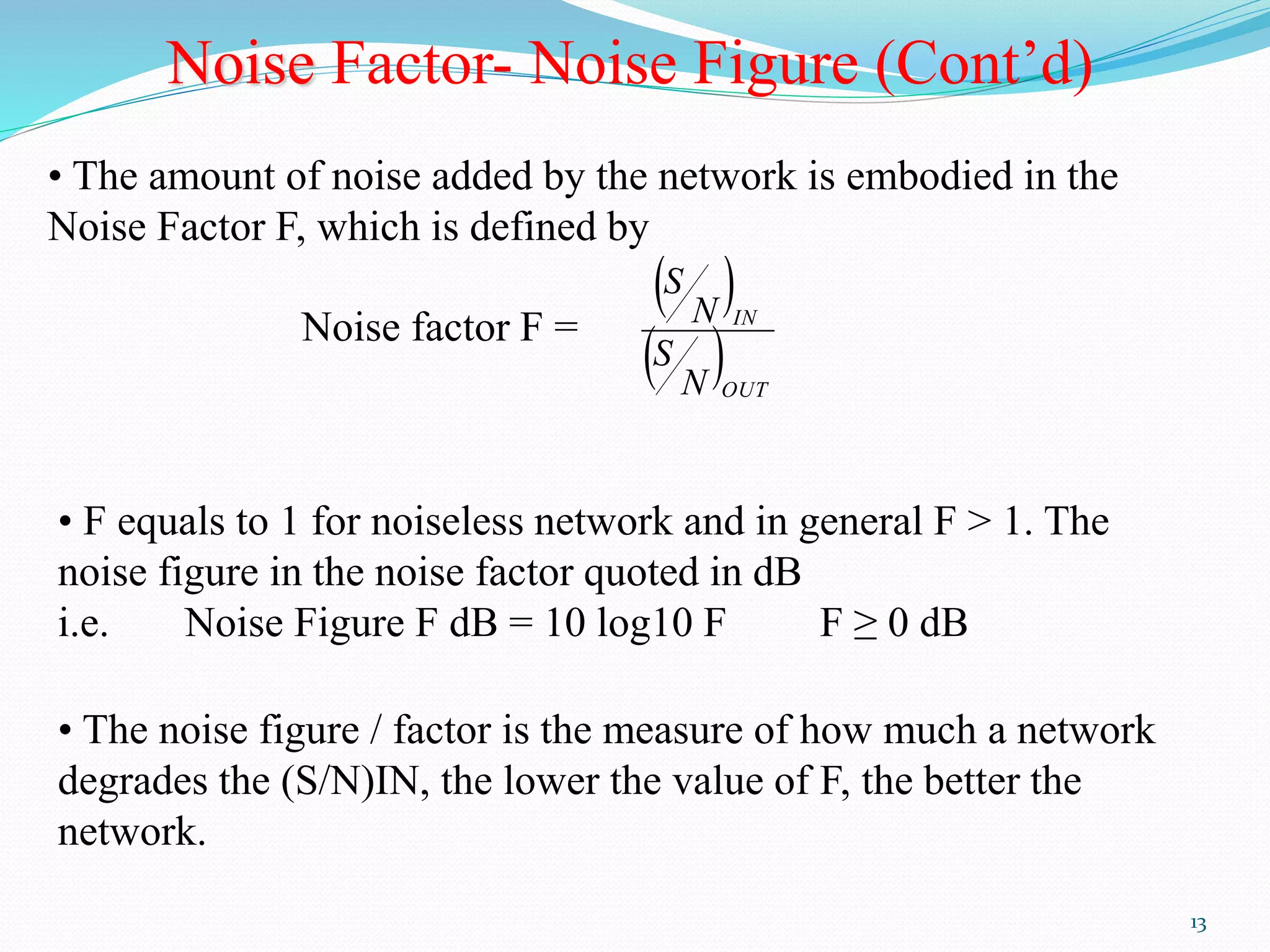
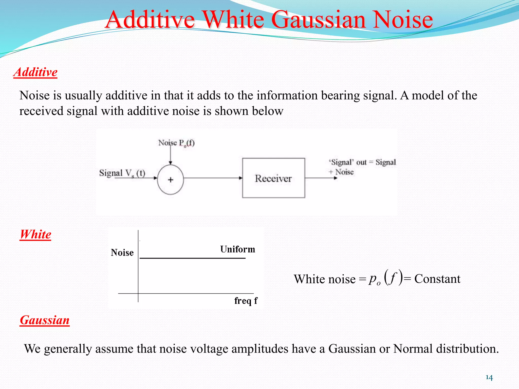
Presented by: 
Firdous Ahmad 
Mohd Kabir 
M.Tech(ECE) 
Pondicherry university
contents: 
Introduction of noise 
Types of noise 
1) Thermal Noise 
2).Shot Noise 
3).Low Frequency or Flicker Noise 
4).Excess Resister Noise 
5).Burst or Popcorn Noise 
• Analysis of Noise in Communication Systems 
• Thermal Noise 
• Noise Voltage Spectral Density 
• Resistors in Series 
• Resistors in Parallel 
• Signal - to – Noise 
• Noise Factor – 
• System Noise Figure 
•Additive White Gaussian Noise
Introduction of Noise 
Noise is a general term which is used to describe an unwanted 
signal which affects a wanted signal. These unwanted signals arise 
from a variety of sources which may be considered in one of two 
main categories:- 
•Interference, usually from a human source (man made) 
•Naturally occurring random noise 
Interference 
Interference arises for example, from other communication 
systems (cross talk), 50 Hz supplies (hum) and harmonics, 
switched mode power supplies, thyristor circuits, ignition (car 
spark plugs) motors … etc.
Natural Noise 
Naturally occuring external noise sources include atmosphere 
disturbance (e.g. electric storms, lighting, ionospheric effect etc), 
so called ‘Sky Noise’ or Cosmic noise which includes noise from 
galaxy, solar noise and ‘hot spot’ due to oxygen and water vapour 
resonance in the earth’s atmosphere.
Thermal Noise (Johnson Noise) 
This type of noise is generated by all resistances (e.g. a resistor, 
semiconductor, the resistance of a resonant circuit, i.e. the real part 
of the impedance, cable etc). 
Experimental results (by Johnson) and theoretical 
studies (by Nyquist) give the mean square noise 
voltage as 
_ 2 
V  k TBR volt 
4 ( ) 2 
Where k = Boltzmann’s constant = 1.38 x 10⁻²³ Joules per K 
T = absolute temperature 
B = bandwidth noise measured in (Hz) 
R = resistance (ohms)
Thermal Noise (Johnson Noise ) (Cont’d) 
The law relating noise power, N, to the temperature and 
bandwidth is 
N = k TB watts 
Thermal noise is often referred to as ‘white noise’ because it has a 
uniform ‘spectral density’.
Shot Noise 
• Shot noise was originally used to describe noise due to random 
fluctuations in electron emission from cathodes in vacuum tubes (called 
shot noise by analogy with lead shot). 
• Shot noise also occurs in semiconductors due to the liberation of charge 
carriers. 
• For pn junctions the mean square shot noise current is 
Where 
2   2 I 2 I 2 I q B (amps) n DC o e   
is the direct current as the pn junction (amps) 
is the reverse saturation current (amps) 
is the electron charge = 1.6 x 10⁻¹⁹ coulombs 
B is the effective noise bandwidth (Hz) 
• Shot noise is found to have a uniform spectral density as for thermal 
noise
Low Frequency or Flicker Noeis 
Active devices, integrated circuit, diodes, transistors etc also 
exhibits a low frequency noise, which is frequency dependent (i.e. 
non uniform) known as flicker noise or ‘one – over – f’ noise. 
Excess Resistor Noise 
Thermal noise in resistors does not vary with frequency, as 
previously noted, by many resistors also generates as additional 
frequency dependent noise referred to as excess noise. 
Burst Noise or Popcorn Noise 
Some semiconductors also produce burst or popcorn noise with a 
spectral density which is proportional to 2 
1  
 
 
 
 
 
f
Analysis of Noise In Communication Systems 
Thermal Noise (Johnson noise) 
This thermal noise may be represented by an equivalent circuit 
as shown below 
A) System BW = B Hz 
N= Constant B (watts) = KB 
B) System BW 
N= Constant 2B (watts) = 
K2B 
S 
KB 
S 
For A,  
N 
S 
K B 
S 
N 
2 
For B,  
4 ( ) 2 
____ 
2 V  k TBR volt 
(mean square value , power) 
then VRMS 
i.e. Vn is the RMS noise voltage 
n  2 kTBR V
10 
Analysis of Noise In Communication Systems (Cont’d) 
Resistors in Series 
Assume that R1 at 
temperature T1 and R2 at 
temperature T2, then 
2 
2 
___ 
2 
1 
____ ___ 
2 
n n n V V  V 
1 1 
____ 
2 
1 V 4kT BR n  
2 2 
____ 
2 
2 V 4kT B R n  
4 ( ) 1 1 2 2 
____ 
2 V k B T R T R n    
4 ( ) 1 2 
____ 
2 V kT B R R n   
i.e. The resistor in series at same temperature behave as a 
single resistor
Analysis of Noise In Communication Systems (Cont’d) 
R R 
1 2 
11 
Resistance in Parallel 
2 
R 
V Vo n  
1 1 R R 
1 2 
 
R 
1 
V Vo n  
2 2 R R 
1 2 
 
2 
2 
___ 
2 
1 
____ ___ 
2 
n o o V  V  V 
 
____ 
4 
kB 
2 
n V   
 
 
    
 
  
 
2 
  
2 2 
1 1 1 
2 
2 2 
 1 2 
1 2 
R R 
R T R R T R 
R R 
kBR R T R T R 
1 2 1 1 2 2 
 2 
1 2 
_____ 
2 4 ( ) 
R R 
Vn 
 
 
 
 
  
 
 
  
 
R R 
1 2 
 
 
1 2 
_____ 
2 4 
R R 
V kTB n
12 
Signal to Noise 
The signal to noise ratio is given by 
SignalPower 
Noise Power 
S 
N 
 
The signal to noise in dB is expressed by 
 
 
 
 
 
 
 
  
 
 
 
 
S 
N 
S 
N 
dB 10 10 log 
dB dBm dBm S N 
S 
N 
 
   
 
 
for S and N measured in mW. 
Noise Factor- Noise Figure 
Consider the network shown below,
13 
Noise Factor- Noise Figure (Cont’d) 
• The amount of noise added by the network is embodied in the 
Noise Factor F, which is defined by 
Noise factor F = 
  
  
IN 
OUT 
N 
S 
N 
S 
• F equals to 1 for noiseless network and in general F > 1. The 
noise figure in the noise factor quoted in dB 
i.e. Noise Figure F dB = 10 log10 F F ≥ 0 dB 
• The noise figure / factor is the measure of how much a network 
degrades the (S/N)IN, the lower the value of F, the better the 
network.
14 
Additive White Gaussian Noise 
Additive 
Noise is usually additive in that it adds to the information bearing signal. A model of the 
received signal with additive noise is shown below 
White 
White noise = p  f  o = Constant 
Gaussian 
We generally assume that noise voltage amplitudes have a Gaussian or Normal distribution.
References: 
1 Principles Of Communication (6th 
Edition)by Sanjay Sharma S. K. 
Kataria & Sons, 2009 
2 Electronic communication system 
by george kennedy & Bernad 
davis,4th edition,2009 
3 communication systems-1 by J.S 
Chitode revised edition 2007- 2008 
4 communication & signal 
processing by Herbert Taub & 
Donald L.Shiling McGraw-Hill 1986 
5 communication theory by T G 
Thomas S Chandra Sekhar 2005 
edition
Thank you

Noise in communication system

  • 1.
    Presented by: FirdousAhmad Mohd Kabir M.Tech(ECE) Pondicherry university
  • 2.
    contents: Introduction ofnoise Types of noise 1) Thermal Noise 2).Shot Noise 3).Low Frequency or Flicker Noise 4).Excess Resister Noise 5).Burst or Popcorn Noise • Analysis of Noise in Communication Systems • Thermal Noise • Noise Voltage Spectral Density • Resistors in Series • Resistors in Parallel • Signal - to – Noise • Noise Factor – • System Noise Figure •Additive White Gaussian Noise
  • 3.
    Introduction of Noise Noise is a general term which is used to describe an unwanted signal which affects a wanted signal. These unwanted signals arise from a variety of sources which may be considered in one of two main categories:- •Interference, usually from a human source (man made) •Naturally occurring random noise Interference Interference arises for example, from other communication systems (cross talk), 50 Hz supplies (hum) and harmonics, switched mode power supplies, thyristor circuits, ignition (car spark plugs) motors … etc.
  • 4.
    Natural Noise Naturallyoccuring external noise sources include atmosphere disturbance (e.g. electric storms, lighting, ionospheric effect etc), so called ‘Sky Noise’ or Cosmic noise which includes noise from galaxy, solar noise and ‘hot spot’ due to oxygen and water vapour resonance in the earth’s atmosphere.
  • 5.
    Thermal Noise (JohnsonNoise) This type of noise is generated by all resistances (e.g. a resistor, semiconductor, the resistance of a resonant circuit, i.e. the real part of the impedance, cable etc). Experimental results (by Johnson) and theoretical studies (by Nyquist) give the mean square noise voltage as _ 2 V  k TBR volt 4 ( ) 2 Where k = Boltzmann’s constant = 1.38 x 10⁻²³ Joules per K T = absolute temperature B = bandwidth noise measured in (Hz) R = resistance (ohms)
  • 6.
    Thermal Noise (JohnsonNoise ) (Cont’d) The law relating noise power, N, to the temperature and bandwidth is N = k TB watts Thermal noise is often referred to as ‘white noise’ because it has a uniform ‘spectral density’.
  • 7.
    Shot Noise •Shot noise was originally used to describe noise due to random fluctuations in electron emission from cathodes in vacuum tubes (called shot noise by analogy with lead shot). • Shot noise also occurs in semiconductors due to the liberation of charge carriers. • For pn junctions the mean square shot noise current is Where 2   2 I 2 I 2 I q B (amps) n DC o e   is the direct current as the pn junction (amps) is the reverse saturation current (amps) is the electron charge = 1.6 x 10⁻¹⁹ coulombs B is the effective noise bandwidth (Hz) • Shot noise is found to have a uniform spectral density as for thermal noise
  • 8.
    Low Frequency orFlicker Noeis Active devices, integrated circuit, diodes, transistors etc also exhibits a low frequency noise, which is frequency dependent (i.e. non uniform) known as flicker noise or ‘one – over – f’ noise. Excess Resistor Noise Thermal noise in resistors does not vary with frequency, as previously noted, by many resistors also generates as additional frequency dependent noise referred to as excess noise. Burst Noise or Popcorn Noise Some semiconductors also produce burst or popcorn noise with a spectral density which is proportional to 2 1       f
  • 9.
    Analysis of NoiseIn Communication Systems Thermal Noise (Johnson noise) This thermal noise may be represented by an equivalent circuit as shown below A) System BW = B Hz N= Constant B (watts) = KB B) System BW N= Constant 2B (watts) = K2B S KB S For A,  N S K B S N 2 For B,  4 ( ) 2 ____ 2 V  k TBR volt (mean square value , power) then VRMS i.e. Vn is the RMS noise voltage n  2 kTBR V
  • 10.
    10 Analysis ofNoise In Communication Systems (Cont’d) Resistors in Series Assume that R1 at temperature T1 and R2 at temperature T2, then 2 2 ___ 2 1 ____ ___ 2 n n n V V  V 1 1 ____ 2 1 V 4kT BR n  2 2 ____ 2 2 V 4kT B R n  4 ( ) 1 1 2 2 ____ 2 V k B T R T R n    4 ( ) 1 2 ____ 2 V kT B R R n   i.e. The resistor in series at same temperature behave as a single resistor
  • 11.
    Analysis of NoiseIn Communication Systems (Cont’d) R R 1 2 11 Resistance in Parallel 2 R V Vo n  1 1 R R 1 2  R 1 V Vo n  2 2 R R 1 2  2 2 ___ 2 1 ____ ___ 2 n o o V  V  V  ____ 4 kB 2 n V             2   2 2 1 1 1 2 2 2  1 2 1 2 R R R T R R T R R R kBR R T R T R 1 2 1 1 2 2  2 1 2 _____ 2 4 ( ) R R Vn            R R 1 2   1 2 _____ 2 4 R R V kTB n
  • 12.
    12 Signal toNoise The signal to noise ratio is given by SignalPower Noise Power S N  The signal to noise in dB is expressed by              S N S N dB 10 10 log dB dBm dBm S N S N       for S and N measured in mW. Noise Factor- Noise Figure Consider the network shown below,
  • 13.
    13 Noise Factor-Noise Figure (Cont’d) • The amount of noise added by the network is embodied in the Noise Factor F, which is defined by Noise factor F =     IN OUT N S N S • F equals to 1 for noiseless network and in general F > 1. The noise figure in the noise factor quoted in dB i.e. Noise Figure F dB = 10 log10 F F ≥ 0 dB • The noise figure / factor is the measure of how much a network degrades the (S/N)IN, the lower the value of F, the better the network.
  • 14.
    14 Additive WhiteGaussian Noise Additive Noise is usually additive in that it adds to the information bearing signal. A model of the received signal with additive noise is shown below White White noise = p  f  o = Constant Gaussian We generally assume that noise voltage amplitudes have a Gaussian or Normal distribution.
  • 15.
    References: 1 PrinciplesOf Communication (6th Edition)by Sanjay Sharma S. K. Kataria & Sons, 2009 2 Electronic communication system by george kennedy & Bernad davis,4th edition,2009 3 communication systems-1 by J.S Chitode revised edition 2007- 2008 4 communication & signal processing by Herbert Taub & Donald L.Shiling McGraw-Hill 1986 5 communication theory by T G Thomas S Chandra Sekhar 2005 edition
  • 16.

Editor's Notes