Downloaded 79 times
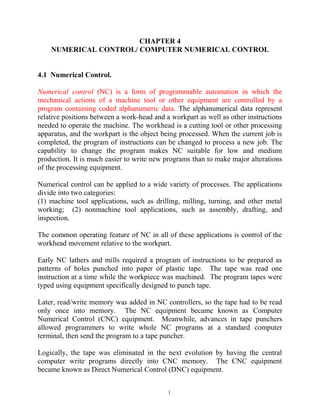
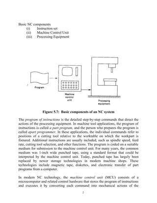

Numerical control (NC) is a form of programmable automation that uses coded alphanumeric data to control the mechanical actions of machine tools. This data represents positions of the workhead and workpart and other instructions. Early NC used punched paper tape to store programs, but later computer numerical control (CNC) added memory and allowed programs to be written at a computer terminal. CNC equipment consists of a machine control unit that stores and executes part programs to control processing equipment like machine tools. Part programs contain instructions for tool positions, speeds, and other functions to transform a workpiece.