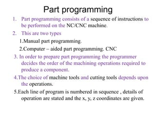
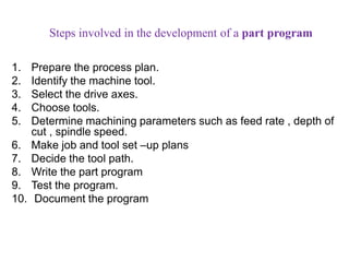
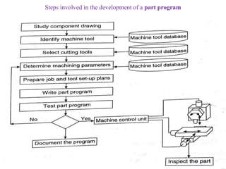
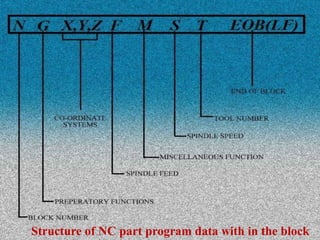
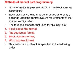
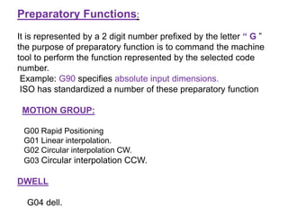
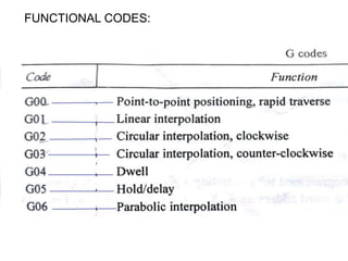
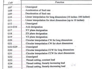
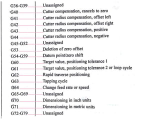
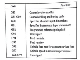
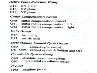
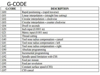
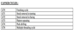
Part programming
1. Part programming consists of a sequence of instructions to
be performed on the NC/CNC machine.
2. This are two types
1.Manual part programming.
2.Computer – aided part programming. CNC
3. In order to prepare part programming the programmer
decides the order of the machining operations required to
produce a component.
4.The choice of machine tools and cutting tools depends upon
the operations.
5.Each line of program is numbered in sequence , details of
operation are stated and the x, y, z coordinates are given.
Steps involved in the development of a part program
1. Prepare the process plan.
2. Identify the machine tool.
3. Select the drive axes.
4. Choose tools.
5. Determine machining parameters such as feed rate , depth of
cut , spindle speed.
6. Make job and tool set –up plans
7. Decide the tool path.
8. Write the part program
9. Test the program.
10. Document the program
Steps involved in the development of a part program
Structure of NC part program data with in the block
Methods of manual part programming
• NC information is passed to MCU in the block format /
statements
• Each block of NC data may be arranged differently ,
depends upon the control system requirements of the
system configuration.
• The four basic tape format used for NC input are:
1. Fixed sequential format
2. Tab sequential format
3. Block address format,
4. Word address format.
• Data within an NC block is specified in the following
order
1. Fixed sequential tape format:
In each NC block same length and and to contain the same
number of characters are used.
Example: if feed and speed are the same for ten blocks of NC
data , f and s must coded in each block.
0050 00 +0025400 +0012500 +0000000 0000 00
0060 01 +0025400 +0012500 -0010000 0500 08
0070 00 +0025400 +0012500 +0000000 0000 09
2. Block address tape format:
In subsequent NC blocks through the specification of a change
code
the change code follows the blocks and the block,
sequence number , and indicates which values are to be
changed relative to the preceding blocks
3. Tab Sequential Tape Format:
This uses special symbol called the tab to separate data
values within a block.
EXAMPLE:
0050 TAB 00 TAB +0025400 TAB +0012500 TAB +0000000 TAB
0060 TAB 01 TAB TAB TAB - 0010000 TAB 0500 TAB 08
0070 TAB 00 TAB TAB TAB - 0000000 TAB 0000 TAB 09
4. Word address tape format:
It uses alphanumeric data specification. Each data value
is preceded by a letter which indicates the type of data
that follows.
N20 G00 X1.200 Y.100 F325 S1000 T03 M09
This format is used by most of the NC machines, also called
variable block format.
Basic CNC input data
1. Sequence numbers (N code):It is used to identify each block
within the CNC program and provides a means by which CNC
commands may be rapidly located.
Three digit numbers to appear after the N symbol.
N025 Y25 Z0.
2. Co ordinates function: The coordinates of the tool tip are
programmed for generating a given component geometry.
the coordinates are specified by using the word address
X,Y,Z,,U,V,W,I,J,K
for example: X = 100.125 y -25.005 z- 5.565
3. Feed function: the feed rate displacement or spindle feed
rate is expressed in mm/min.
the 3 digit number prefixed by the letter “ F ”
Example : F 125 indicates that the feed rate is 125mm/min
4.Speed function: the spindle speed is expressed in rev/min and
is a three- digit number prefixed by the letter “ S ”
for example: S1000 indicates that the spindle speed is 1000rpm.
5.Tool function: The tool function is used in conjunction with the
miscellaneous function for tool changes (M06),
and as a means of addressing the new tool.
for example : T05 M06 .
The execution of the above statement ensures that the new tool
numbered 05 is set-up.
Preparatory Functions:
It is represented by a 2 digit number prefixed by the letter “ G ”
the purpose of preparatory function is to command the machine
tool to perform the function represented by the selected code
number.
Example: G90 specifies absolute input dimensions.
ISO has standardized a number of these preparatory function
MOTION GROUP:
G00 Rapid Positioning
G01 Linear interpolation.
G02 Circular interpolation CW.
G03 Circular interpolation CCW.
DWELL
G04 dell.
FUNCTIONAL CODES:
G-CODE
LIST :
Miscellaneous Functions:
This functions involve actions that are necessary for machining
(spindle on/off , coolant on/off).
These are used to designate a particular mode of operation for
a CNC machine tool.
Program Number:
The symbol used for program number is ‘O’ or
“:” followed by its number.
Example:0123 or :123
The program number does not interference with
the execution of the CNC program.
Interpolation:
1. Linear interpolation in practice are 2 types
linear and circular
2. parabolic and cubic interpolation are also available for
use in the more advanced system.
Definition: it is method that develops intermediate
coordinate points on a straight line between the given start and finish
points.
2.The input contains discrete information in the form of absolute
or incremental movements.
3. G CODE for linear interpolation is G01.
4.When motion is desired along a straight line at a given feed
rate the function is used.
5.If the cut has to be made from A to B at feed rate of 200
mm/min as shown , then the block is written as:
Circular interpolation:
1.It is used to traverse along an arc.
2.G- code for circular interpolation is G02 (for CWD) or G03
(CCD)
3.when the motion is A to B in a XY plane as shown the block is
written by.
Canned cycles:
A canned cycle consists of a series of motions repeated a number of
times like drilling , boring and tapping
Example: A drilling cycle consists following motion of drill bit:
1.Rapid approach to work piece
2.Drill at feed rate
3.rapid return to initial position
Manual part programming

Manual part programming

  • 4.
    Part programming 1. Partprogramming consists of a sequence of instructions to be performed on the NC/CNC machine. 2. This are two types 1.Manual part programming. 2.Computer – aided part programming. CNC 3. In order to prepare part programming the programmer decides the order of the machining operations required to produce a component. 4.The choice of machine tools and cutting tools depends upon the operations. 5.Each line of program is numbered in sequence , details of operation are stated and the x, y, z coordinates are given.
  • 5.
    Steps involved inthe development of a part program 1. Prepare the process plan. 2. Identify the machine tool. 3. Select the drive axes. 4. Choose tools. 5. Determine machining parameters such as feed rate , depth of cut , spindle speed. 6. Make job and tool set –up plans 7. Decide the tool path. 8. Write the part program 9. Test the program. 10. Document the program
  • 6.
    Steps involved inthe development of a part program
  • 7.
    Structure of NCpart program data with in the block
  • 8.
    Methods of manualpart programming • NC information is passed to MCU in the block format / statements • Each block of NC data may be arranged differently , depends upon the control system requirements of the system configuration. • The four basic tape format used for NC input are: 1. Fixed sequential format 2. Tab sequential format 3. Block address format, 4. Word address format. • Data within an NC block is specified in the following order
  • 9.
    1. Fixed sequentialtape format: In each NC block same length and and to contain the same number of characters are used. Example: if feed and speed are the same for ten blocks of NC data , f and s must coded in each block. 0050 00 +0025400 +0012500 +0000000 0000 00 0060 01 +0025400 +0012500 -0010000 0500 08 0070 00 +0025400 +0012500 +0000000 0000 09 2. Block address tape format: In subsequent NC blocks through the specification of a change code the change code follows the blocks and the block, sequence number , and indicates which values are to be changed relative to the preceding blocks
  • 10.
    3. Tab SequentialTape Format: This uses special symbol called the tab to separate data values within a block. EXAMPLE: 0050 TAB 00 TAB +0025400 TAB +0012500 TAB +0000000 TAB 0060 TAB 01 TAB TAB TAB - 0010000 TAB 0500 TAB 08 0070 TAB 00 TAB TAB TAB - 0000000 TAB 0000 TAB 09 4. Word address tape format: It uses alphanumeric data specification. Each data value is preceded by a letter which indicates the type of data that follows. N20 G00 X1.200 Y.100 F325 S1000 T03 M09 This format is used by most of the NC machines, also called variable block format.
  • 11.
    Basic CNC inputdata 1. Sequence numbers (N code):It is used to identify each block within the CNC program and provides a means by which CNC commands may be rapidly located. Three digit numbers to appear after the N symbol. N025 Y25 Z0. 2. Co ordinates function: The coordinates of the tool tip are programmed for generating a given component geometry. the coordinates are specified by using the word address X,Y,Z,,U,V,W,I,J,K for example: X = 100.125 y -25.005 z- 5.565 3. Feed function: the feed rate displacement or spindle feed rate is expressed in mm/min. the 3 digit number prefixed by the letter “ F ” Example : F 125 indicates that the feed rate is 125mm/min
  • 12.
    4.Speed function: thespindle speed is expressed in rev/min and is a three- digit number prefixed by the letter “ S ” for example: S1000 indicates that the spindle speed is 1000rpm. 5.Tool function: The tool function is used in conjunction with the miscellaneous function for tool changes (M06), and as a means of addressing the new tool. for example : T05 M06 . The execution of the above statement ensures that the new tool numbered 05 is set-up.
  • 13.
    Preparatory Functions: It isrepresented by a 2 digit number prefixed by the letter “ G ” the purpose of preparatory function is to command the machine tool to perform the function represented by the selected code number. Example: G90 specifies absolute input dimensions. ISO has standardized a number of these preparatory function MOTION GROUP: G00 Rapid Positioning G01 Linear interpolation. G02 Circular interpolation CW. G03 Circular interpolation CCW. DWELL G04 dell.
  • 14.
  • 19.
  • 21.
    Miscellaneous Functions: This functionsinvolve actions that are necessary for machining (spindle on/off , coolant on/off). These are used to designate a particular mode of operation for a CNC machine tool. Program Number: The symbol used for program number is ‘O’ or “:” followed by its number. Example:0123 or :123 The program number does not interference with the execution of the CNC program.
  • 23.
    Interpolation: 1. Linear interpolationin practice are 2 types linear and circular 2. parabolic and cubic interpolation are also available for use in the more advanced system. Definition: it is method that develops intermediate coordinate points on a straight line between the given start and finish points. 2.The input contains discrete information in the form of absolute or incremental movements. 3. G CODE for linear interpolation is G01. 4.When motion is desired along a straight line at a given feed rate the function is used. 5.If the cut has to be made from A to B at feed rate of 200 mm/min as shown , then the block is written as:
  • 25.
    Circular interpolation: 1.It isused to traverse along an arc. 2.G- code for circular interpolation is G02 (for CWD) or G03 (CCD) 3.when the motion is A to B in a XY plane as shown the block is written by.
  • 26.
    Canned cycles: A cannedcycle consists of a series of motions repeated a number of times like drilling , boring and tapping Example: A drilling cycle consists following motion of drill bit: 1.Rapid approach to work piece 2.Drill at feed rate 3.rapid return to initial position