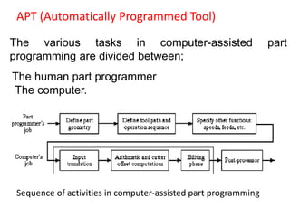
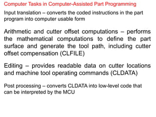
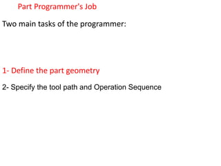
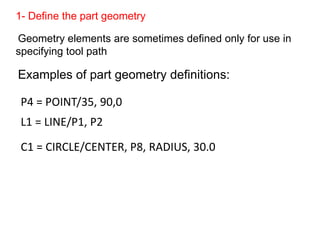
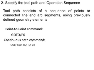
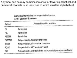
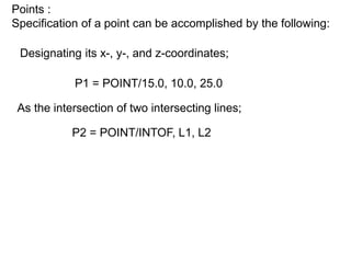
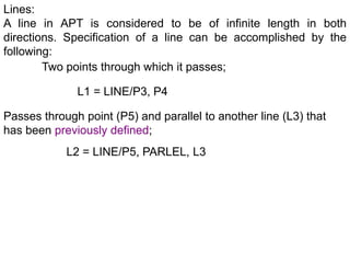
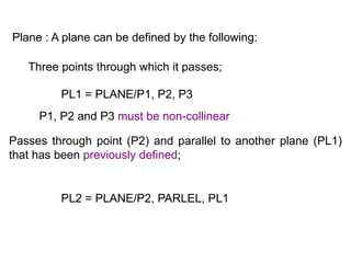
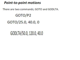
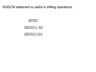
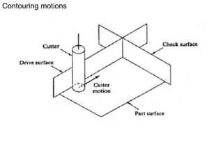
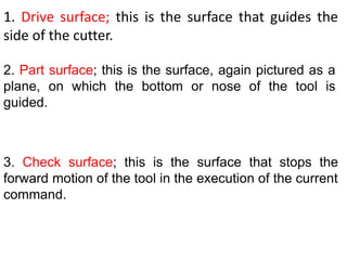
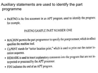
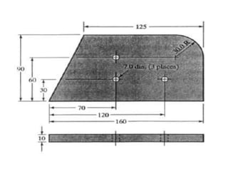
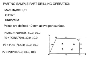
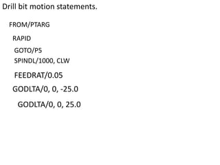
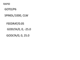
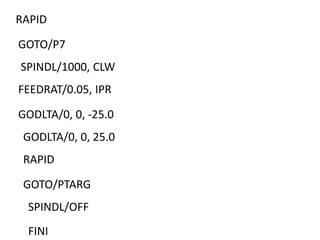
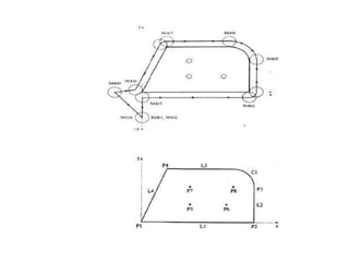
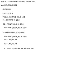
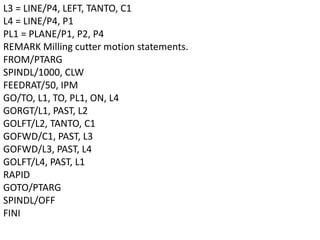
SlideShare a Scribd company logo
Dr. V.Chittaranjan Das
Professor ,
Department of Mechanical Engineering,Guntur
Computer assisted part programming
(APT, Automatically Programmed Tool)
Manual part programming is time-consuming, tedious, and
subject to human errors for complex jobs.
Machining instructions are written in English-like statements that
are translated by the computer into the low-level machine code
of the MCU.
It is used for more complex jobs.
APT (Automatically Programmed Tool)
The various tasks in computer-assisted part
programming are divided between;
The human part programmer
The computer.
Sequence of activities in computer-assisted part programming
Computer Tasks in Computer-Assisted Part Programming
Input translation – converts the coded instructions in the part
program into computer usable form
Arithmetic and cutter offset computations – performs
the mathematical computations to define the part
surface and generate the tool path, including cutter
offset compensation (CLFILE)
Editing – provides readable data on cutter locations
and machine tool operating commands (CLDATA)
Post processing – converts CLDATA into low-level code that
can be interpreted by the MCU
Part Programmer's Job
Two main tasks of the programmer:
1- Define the part geometry
2- Specify the tool path and Operation Sequence
1- Define the part geometry
Geometry elements are sometimes defined only for use in
specifying tool path
Examples of part geometry definitions:
P4 = POINT/35, 90,0
L1 = LINE/P1, P2
C1 = CIRCLE/CENTER, P8, RADIUS, 30.0
2- Specify the tool path and Operation Sequence
Tool path consists of a sequence of points or
connected line and arc segments, using previously
defined geometry elements
Point-to-Point command:
GOTO/P0
Continuous path command:
GOLFT/L2, TANTO, C1
Other Functions in Computer-Assisted Part Programming
Specifying cutting speeds and feed rates
Designating cutter size (for tool offset calculations)
Specifying tolerances in circular interpolation
Naming the program
Identifying the machine tool
Cutter Offset
Cutter path must be offset from actual part outline by
A distance equal to the cutter radius
There are four basic types of statements in the APT language:
Geometry statements, also called definition statements; are used
to define the geometry elements that comprise the part.
Motion commands; are used to specify the tool path.
Postprocessor statements; control the machine tool operation,
for example, to specify speeds and feeds, set tolerance values
for circular interpolation, and actuate other capabilities of the
machine tool.
Auxiliary statements; a group of miscellaneous statements
used to name the part program, insert comments in the
program and accomplish similar functions.
APT vocabulary words consist of six or fewer characters. The
characters are almost always letters of the alphabet.
Geometry statements
The points, lines, and surfaces must be defined in the program
prior to specifying the motion statements.
SYMBOL = GEOMETRY TYPE/descriptive data
A symbol can be may combination of six or fewer alphabetical and
numerical characters, at least one of which must be alphabetical.
Points :
Specification of a point can be accomplished by the following:
Designating its x-, y-, and z-coordinates;
P1 = POINT/15.0, 10.0, 25.0
As the intersection of two intersecting lines;
P2 = POINT/INTOF, L1, L2
Lines:
A line in APT is considered to be of infinite length in both
directions. Specification of a line can be accomplished by the
following:
Two points through which it passes;
L1 = LINE/P3, P4
Passes through point (P5) and parallel to another line (L3) that
has been previously defined;
L2 = LINE/P5, PARLEL, L3
Plane : A plane can be defined by the following:
Three points through which it passes;
PL1 = PLANE/P1, P2, P3
P1, P2 and P3 must be non-collinear
Passes through point (P2) and parallel to another plane (PL1)
that has been previously defined;
PL2 = PLANE/P2, PARLEL, PL1
center and radius
C1 = CIRCLE/CENTER, P1, RADIUS, 25.0
Three points through which it passes;
C2 = CIRCLE/P4, P5, P6
Circle:
APT Rules:
A symbol can be used to define only one geometry element
Only one symbol can be used to define any given element
GODLTA statement is useful in drilling operations.
Contouring motions
1. Drive surface; this is the surface that guides the
side of the cutter.
2. Part surface; this is the surface, again pictured as a
plane, on which the bottom or nose of the tool is
guided.
3. Check surface; this is the surface that stops the
forward motion of the tool in the execution of the current
command.
APT Modified words:
TO,ON,PAST
TANTO: Drive surface is tangent to the check surface
FROM/PTARG
GO/TO, PL1, TO, PL2, TO, PL3
FROM/PTARG
GO/TO, L1, TO, PL2, TO, L3
GORGT/L3, PAST, L4
Postprocessor and Auxiliary statements
POSTPROCESSOR COMMAND/descriptive data
Auxiliary statements are used to identify the part
programme
PARTNO SAMPLE PART DRILLING OPERATION
MACHIN/DRILL,01
CLPRNT
UNITS/MM
Points are defined 10 mm above part surface.
PTARG = POINT/0, -50.0, 10.0
P5 = POINT/70.0, 30.0, 10.0
P6 = POINT/120.0, 30.0, 10.0
P7 = POINT/70.0, 60.0, 10.0
Drill bit motion statements.
FROM/PTARG
RAPID
GOTO/P5
SPINDL/1000, CLW
FEEDRAT/0.05
GODLTA/0, 0, -25.0
GODLTA/0, 0, 25.0
RAPID
GOTO/P6
GODLTA/0, 0, 25.0
SPINDL/1000, CLW
FEEDRAT/0.05
GODLTA/0, 0, -25.0
RAPID
GOTO/P7
SPINDL/1000, CLW
FEEDRAT/0.05, IPR
GODLTA/0, 0, -25.0
GODLTA/0, 0, 25.0
RAPID
GOTO/PTARG
SPINDL/OFF
FINI
PARTNO SAMPLE PART MILLING OPERATION
MACHIN/MILLING,02
UNITS/MM
CUTTER/20.0
PTARG = POINT/0, -50.0, 10.0
P1 = POINT/0, 0, -25.0
P2 = POINT/160.0, 0, -25.0
P3 = POINT/160.0, 60.0, -25.0
P4 = POINT/35.0, 90.0, -25.0
P8 = POINT/130.0, 60.0, -25.0
L1 = LINE/P1, P2
L2 = LINE/P2, P3
C1 = CIRCLE/CENTER, P8, RADIUS, 30.0
L3 = LINE/P4, LEFT, TANTO, C1
L4 = LINE/P4, P1
PL1 = PLANE/P1, P2, P4
REMARK Milling cutter motion statements.
FROM/PTARG
SPINDL/1000, CLW
FEEDRAT/50, IPM
GO/TO, L1, TO, PL1, ON, L4
GORGT/L1, PAST, L2
GOLFT/L2, TANTO, C1
GOFWD/C1, PAST, L3
GOFWD/L3, PAST, L4
GOLFT/L4, PAST, L1
RAPID
GOTO/PTARG
SPINDL/OFF
FINI
Apt programming

More Related Content

What's hot

Chapter 3 CNC turning and machining centers
Chapter 3 CNC turning and machining centersChapter 3 CNC turning and machining centers
Chapter 3 CNC turning and machining centersRAHUL THAKER
 
CNC part programming
CNC part programmingCNC part programming
CNC part programmingjntuhcej
 
Numerical control machines
Numerical control machines Numerical control machines
Numerical control machines jntuhcej
 
Layout of FMS
Layout of FMSLayout of FMS
Layout of FMSsgrsoni45
 
Cnc axis and motion nomenclature
Cnc axis and motion nomenclatureCnc axis and motion nomenclature
Cnc axis and motion nomenclaturemeet shah
 
FUNDAMENTALS OF CNC & PART PROGRAMMING - UNIT - 4 CAD&M
FUNDAMENTALS OF CNC & PART PROGRAMMING - UNIT - 4 CAD&MFUNDAMENTALS OF CNC & PART PROGRAMMING - UNIT - 4 CAD&M
FUNDAMENTALS OF CNC & PART PROGRAMMING - UNIT - 4 CAD&MBalamurugan Subburaj
 
COMPUTER AIDED PROCESS PLANNING
COMPUTER AIDED PROCESS PLANNINGCOMPUTER AIDED PROCESS PLANNING
COMPUTER AIDED PROCESS PLANNINGjntuhcej
 
CNC Part programming
CNC Part programmingCNC Part programming
CNC Part programmingjani parth
 
Fundamentals of GD&T-1.pdf
Fundamentals of GD&T-1.pdfFundamentals of GD&T-1.pdf
Fundamentals of GD&T-1.pdfMuzzammil12
 
Computer numerical control (CNC)
Computer numerical control (CNC)Computer numerical control (CNC)
Computer numerical control (CNC)Sudip Phuyal
 
Part programming for nc machines
Part programming for nc machinesPart programming for nc machines
Part programming for nc machinesDorothy Kare
 
Cnc, dnc & adaptive control
Cnc, dnc & adaptive controlCnc, dnc & adaptive control
Cnc, dnc & adaptive controlparabajinkya0070
 
12 cnc & part programming
12 cnc & part programming12 cnc & part programming
12 cnc & part programmingM Siva Kumar
 

What's hot (20)

Chapter 3 CNC turning and machining centers
Chapter 3 CNC turning and machining centersChapter 3 CNC turning and machining centers
Chapter 3 CNC turning and machining centers
 
DNC SYSTEMS
DNC SYSTEMSDNC SYSTEMS
DNC SYSTEMS
 
CNC part programming
CNC part programmingCNC part programming
CNC part programming
 
Numerical control machines
Numerical control machines Numerical control machines
Numerical control machines
 
CNC Programming
CNC Programming CNC Programming
CNC Programming
 
Milling Fixture
Milling FixtureMilling Fixture
Milling Fixture
 
Nc part programming
Nc part programmingNc part programming
Nc part programming
 
Gear manufacturing
Gear manufacturingGear manufacturing
Gear manufacturing
 
Nc Machine
Nc MachineNc Machine
Nc Machine
 
Layout of FMS
Layout of FMSLayout of FMS
Layout of FMS
 
Cnc axis and motion nomenclature
Cnc axis and motion nomenclatureCnc axis and motion nomenclature
Cnc axis and motion nomenclature
 
FUNDAMENTALS OF CNC & PART PROGRAMMING - UNIT - 4 CAD&M
FUNDAMENTALS OF CNC & PART PROGRAMMING - UNIT - 4 CAD&MFUNDAMENTALS OF CNC & PART PROGRAMMING - UNIT - 4 CAD&M
FUNDAMENTALS OF CNC & PART PROGRAMMING - UNIT - 4 CAD&M
 
COMPUTER AIDED PROCESS PLANNING
COMPUTER AIDED PROCESS PLANNINGCOMPUTER AIDED PROCESS PLANNING
COMPUTER AIDED PROCESS PLANNING
 
CNC Part programming
CNC Part programmingCNC Part programming
CNC Part programming
 
Fundamentals of GD&T-1.pdf
Fundamentals of GD&T-1.pdfFundamentals of GD&T-1.pdf
Fundamentals of GD&T-1.pdf
 
Computer numerical control (CNC)
Computer numerical control (CNC)Computer numerical control (CNC)
Computer numerical control (CNC)
 
Part programming for nc machines
Part programming for nc machinesPart programming for nc machines
Part programming for nc machines
 
Cnc, dnc & adaptive control
Cnc, dnc & adaptive controlCnc, dnc & adaptive control
Cnc, dnc & adaptive control
 
12 cnc & part programming
12 cnc & part programming12 cnc & part programming
12 cnc & part programming
 
Ch 2 NC machine
Ch 2 NC machine Ch 2 NC machine
Ch 2 NC machine
 

Similar to Apt programming

Computer assisted part programming.pdf
Computer assisted part programming.pdfComputer assisted part programming.pdf
Computer assisted part programming.pdfAshok Mannava
 
APT Programming in CAD CAM CIM for CNC programming
APT Programming in CAD CAM CIM for CNC programmingAPT Programming in CAD CAM CIM for CNC programming
APT Programming in CAD CAM CIM for CNC programmingamitchaudhari65
 
NC part programing & Robotics
NC part programing & RoboticsNC part programing & Robotics
NC part programing & RoboticsDenny John
 
7-CNC_Programming_For_Lathe_na_eng.pdf
7-CNC_Programming_For_Lathe_na_eng.pdf7-CNC_Programming_For_Lathe_na_eng.pdf
7-CNC_Programming_For_Lathe_na_eng.pdfssuser46f1ac
 
Chapter 4 cnc part programming
Chapter 4 cnc part programmingChapter 4 cnc part programming
Chapter 4 cnc part programmingRAHUL THAKER
 
Group 06 batch-2017-cam_date-03-nov-2020
Group 06 batch-2017-cam_date-03-nov-2020Group 06 batch-2017-cam_date-03-nov-2020
Group 06 batch-2017-cam_date-03-nov-2020Dhyey Shukla
 
06. APT_Detailed.pdf
06. APT_Detailed.pdf06. APT_Detailed.pdf
06. APT_Detailed.pdfssuserf3628e
 
Robo unit4- Robot Programming.pptx
Robo unit4- Robot Programming.pptxRobo unit4- Robot Programming.pptx
Robo unit4- Robot Programming.pptxPriya429658
 
Computer programming and utilization
Computer programming and utilizationComputer programming and utilization
Computer programming and utilizationDigvijaysinh Gohil
 
robot-pplication-200916054307.pptx
robot-pplication-200916054307.pptxrobot-pplication-200916054307.pptx
robot-pplication-200916054307.pptxDSelvamarilakshmiAss
 
Robot programming , accuracy ,repeatability and application
Robot programming , accuracy ,repeatability  and applicationRobot programming , accuracy ,repeatability  and application
Robot programming , accuracy ,repeatability and applicationvishaldattKohir1
 
CH-3 CO-all-about-operating-system(Update).pptx
CH-3 CO-all-about-operating-system(Update).pptxCH-3 CO-all-about-operating-system(Update).pptx
CH-3 CO-all-about-operating-system(Update).pptxXyzXyz338506
 
final Unit 1-1.pdf
final Unit 1-1.pdffinal Unit 1-1.pdf
final Unit 1-1.pdfprakashvs7
 

Similar to Apt programming (20)

Computer assisted part programming.pdf
Computer assisted part programming.pdfComputer assisted part programming.pdf
Computer assisted part programming.pdf
 
APT Programming in CAD CAM CIM for CNC programming
APT Programming in CAD CAM CIM for CNC programmingAPT Programming in CAD CAM CIM for CNC programming
APT Programming in CAD CAM CIM for CNC programming
 
NC part programing & Robotics
NC part programing & RoboticsNC part programing & Robotics
NC part programing & Robotics
 
Assembler
AssemblerAssembler
Assembler
 
7-CNC_Programming_For_Lathe_na_eng.pdf
7-CNC_Programming_For_Lathe_na_eng.pdf7-CNC_Programming_For_Lathe_na_eng.pdf
7-CNC_Programming_For_Lathe_na_eng.pdf
 
Chapter 4 cnc part programming
Chapter 4 cnc part programmingChapter 4 cnc part programming
Chapter 4 cnc part programming
 
APT.ppt
APT.pptAPT.ppt
APT.ppt
 
Group 06 batch-2017-cam_date-03-nov-2020
Group 06 batch-2017-cam_date-03-nov-2020Group 06 batch-2017-cam_date-03-nov-2020
Group 06 batch-2017-cam_date-03-nov-2020
 
06. APT_Detailed.pdf
06. APT_Detailed.pdf06. APT_Detailed.pdf
06. APT_Detailed.pdf
 
Robo unit4- Robot Programming.pptx
Robo unit4- Robot Programming.pptxRobo unit4- Robot Programming.pptx
Robo unit4- Robot Programming.pptx
 
Computer programming and utilization
Computer programming and utilizationComputer programming and utilization
Computer programming and utilization
 
robot-pplication-200916054307.pptx
robot-pplication-200916054307.pptxrobot-pplication-200916054307.pptx
robot-pplication-200916054307.pptx
 
Cnc programming basics.doc
Cnc programming basics.docCnc programming basics.doc
Cnc programming basics.doc
 
Robot programming , accuracy ,repeatability and application
Robot programming , accuracy ,repeatability  and applicationRobot programming , accuracy ,repeatability  and application
Robot programming , accuracy ,repeatability and application
 
part programming (cnc)
part programming (cnc)part programming (cnc)
part programming (cnc)
 
Modul PLC Programming.pdf
Modul PLC Programming.pdfModul PLC Programming.pdf
Modul PLC Programming.pdf
 
Resume
ResumeResume
Resume
 
CH-3 CO-all-about-operating-system(Update).pptx
CH-3 CO-all-about-operating-system(Update).pptxCH-3 CO-all-about-operating-system(Update).pptx
CH-3 CO-all-about-operating-system(Update).pptx
 
Sp chap2
Sp chap2Sp chap2
Sp chap2
 
final Unit 1-1.pdf
final Unit 1-1.pdffinal Unit 1-1.pdf
final Unit 1-1.pdf
 

Recently uploaded

Laundry management system project report.pdf
Laundry management system project report.pdfLaundry management system project report.pdf
Laundry management system project report.pdfKamal Acharya
 
Top 13 Famous Civil Engineering Scientist
Top 13 Famous Civil Engineering ScientistTop 13 Famous Civil Engineering Scientist
Top 13 Famous Civil Engineering Scientistgettygaming1
 
RS Khurmi Machine Design Clutch and Brake Exercise Numerical Solutions
RS Khurmi Machine Design Clutch and Brake Exercise Numerical SolutionsRS Khurmi Machine Design Clutch and Brake Exercise Numerical Solutions
RS Khurmi Machine Design Clutch and Brake Exercise Numerical SolutionsAtif Razi
 
Introduction to Machine Learning Unit-5 Notes for II-II Mechanical Engineering
Introduction to Machine Learning Unit-5 Notes for II-II Mechanical EngineeringIntroduction to Machine Learning Unit-5 Notes for II-II Mechanical Engineering
Introduction to Machine Learning Unit-5 Notes for II-II Mechanical EngineeringC Sai Kiran
 
School management system project report.pdf
School management system project report.pdfSchool management system project report.pdf
School management system project report.pdfKamal Acharya
 
CFD Simulation of By-pass Flow in a HRSG module by R&R Consult.pptx
CFD Simulation of By-pass Flow in a HRSG module by R&R Consult.pptxCFD Simulation of By-pass Flow in a HRSG module by R&R Consult.pptx
CFD Simulation of By-pass Flow in a HRSG module by R&R Consult.pptxR&R Consult
 
Cloud-Computing_CSE311_Computer-Networking CSE GUB BD - Shahidul.pptx
Cloud-Computing_CSE311_Computer-Networking CSE GUB BD - Shahidul.pptxCloud-Computing_CSE311_Computer-Networking CSE GUB BD - Shahidul.pptx
Cloud-Computing_CSE311_Computer-Networking CSE GUB BD - Shahidul.pptxMd. Shahidul Islam Prodhan
 
Arduino based vehicle speed tracker project
Arduino based vehicle speed tracker projectArduino based vehicle speed tracker project
Arduino based vehicle speed tracker projectRased Khan
 
Courier management system project report.pdf
Courier management system project report.pdfCourier management system project report.pdf
Courier management system project report.pdfKamal Acharya
 
retail automation billing system ppt.pptx
retail automation billing system ppt.pptxretail automation billing system ppt.pptx
retail automation billing system ppt.pptxfaamieahmd
 
Digital Signal Processing Lecture notes n.pdf
Digital Signal Processing Lecture notes n.pdfDigital Signal Processing Lecture notes n.pdf
Digital Signal Processing Lecture notes n.pdfAbrahamGadissa
 
RESORT MANAGEMENT AND RESERVATION SYSTEM PROJECT REPORT.pdf
RESORT MANAGEMENT AND RESERVATION SYSTEM PROJECT REPORT.pdfRESORT MANAGEMENT AND RESERVATION SYSTEM PROJECT REPORT.pdf
RESORT MANAGEMENT AND RESERVATION SYSTEM PROJECT REPORT.pdfKamal Acharya
 
Event Management System Vb Net Project Report.pdf
Event Management System Vb Net  Project Report.pdfEvent Management System Vb Net  Project Report.pdf
Event Management System Vb Net Project Report.pdfKamal Acharya
 
Pharmacy management system project report..pdf
Pharmacy management system project report..pdfPharmacy management system project report..pdf
Pharmacy management system project report..pdfKamal Acharya
 
Online resume builder management system project report.pdf
Online resume builder management system project report.pdfOnline resume builder management system project report.pdf
Online resume builder management system project report.pdfKamal Acharya
 
Online blood donation management system project.pdf
Online blood donation management system project.pdfOnline blood donation management system project.pdf
Online blood donation management system project.pdfKamal Acharya
 
İTÜ CAD and Reverse Engineering Workshop
İTÜ CAD and Reverse Engineering WorkshopİTÜ CAD and Reverse Engineering Workshop
İTÜ CAD and Reverse Engineering WorkshopEmre Günaydın
 
BRAKING SYSTEM IN INDIAN RAILWAY AutoCAD DRAWING
BRAKING SYSTEM IN INDIAN RAILWAY AutoCAD DRAWINGBRAKING SYSTEM IN INDIAN RAILWAY AutoCAD DRAWING
BRAKING SYSTEM IN INDIAN RAILWAY AutoCAD DRAWINGKOUSTAV SARKAR
 
Halogenation process of chemical process industries
Halogenation process of chemical process industriesHalogenation process of chemical process industries
Halogenation process of chemical process industriesMuhammadTufail242431
 

Recently uploaded (20)

Laundry management system project report.pdf
Laundry management system project report.pdfLaundry management system project report.pdf
Laundry management system project report.pdf
 
Top 13 Famous Civil Engineering Scientist
Top 13 Famous Civil Engineering ScientistTop 13 Famous Civil Engineering Scientist
Top 13 Famous Civil Engineering Scientist
 
RS Khurmi Machine Design Clutch and Brake Exercise Numerical Solutions
RS Khurmi Machine Design Clutch and Brake Exercise Numerical SolutionsRS Khurmi Machine Design Clutch and Brake Exercise Numerical Solutions
RS Khurmi Machine Design Clutch and Brake Exercise Numerical Solutions
 
Introduction to Machine Learning Unit-5 Notes for II-II Mechanical Engineering
Introduction to Machine Learning Unit-5 Notes for II-II Mechanical EngineeringIntroduction to Machine Learning Unit-5 Notes for II-II Mechanical Engineering
Introduction to Machine Learning Unit-5 Notes for II-II Mechanical Engineering
 
School management system project report.pdf
School management system project report.pdfSchool management system project report.pdf
School management system project report.pdf
 
CFD Simulation of By-pass Flow in a HRSG module by R&R Consult.pptx
CFD Simulation of By-pass Flow in a HRSG module by R&R Consult.pptxCFD Simulation of By-pass Flow in a HRSG module by R&R Consult.pptx
CFD Simulation of By-pass Flow in a HRSG module by R&R Consult.pptx
 
Cloud-Computing_CSE311_Computer-Networking CSE GUB BD - Shahidul.pptx
Cloud-Computing_CSE311_Computer-Networking CSE GUB BD - Shahidul.pptxCloud-Computing_CSE311_Computer-Networking CSE GUB BD - Shahidul.pptx
Cloud-Computing_CSE311_Computer-Networking CSE GUB BD - Shahidul.pptx
 
Arduino based vehicle speed tracker project
Arduino based vehicle speed tracker projectArduino based vehicle speed tracker project
Arduino based vehicle speed tracker project
 
Courier management system project report.pdf
Courier management system project report.pdfCourier management system project report.pdf
Courier management system project report.pdf
 
Standard Reomte Control Interface - Neometrix
Standard Reomte Control Interface - NeometrixStandard Reomte Control Interface - Neometrix
Standard Reomte Control Interface - Neometrix
 
retail automation billing system ppt.pptx
retail automation billing system ppt.pptxretail automation billing system ppt.pptx
retail automation billing system ppt.pptx
 
Digital Signal Processing Lecture notes n.pdf
Digital Signal Processing Lecture notes n.pdfDigital Signal Processing Lecture notes n.pdf
Digital Signal Processing Lecture notes n.pdf
 
RESORT MANAGEMENT AND RESERVATION SYSTEM PROJECT REPORT.pdf
RESORT MANAGEMENT AND RESERVATION SYSTEM PROJECT REPORT.pdfRESORT MANAGEMENT AND RESERVATION SYSTEM PROJECT REPORT.pdf
RESORT MANAGEMENT AND RESERVATION SYSTEM PROJECT REPORT.pdf
 
Event Management System Vb Net Project Report.pdf
Event Management System Vb Net  Project Report.pdfEvent Management System Vb Net  Project Report.pdf
Event Management System Vb Net Project Report.pdf
 
Pharmacy management system project report..pdf
Pharmacy management system project report..pdfPharmacy management system project report..pdf
Pharmacy management system project report..pdf
 
Online resume builder management system project report.pdf
Online resume builder management system project report.pdfOnline resume builder management system project report.pdf
Online resume builder management system project report.pdf
 
Online blood donation management system project.pdf
Online blood donation management system project.pdfOnline blood donation management system project.pdf
Online blood donation management system project.pdf
 
İTÜ CAD and Reverse Engineering Workshop
İTÜ CAD and Reverse Engineering WorkshopİTÜ CAD and Reverse Engineering Workshop
İTÜ CAD and Reverse Engineering Workshop
 
BRAKING SYSTEM IN INDIAN RAILWAY AutoCAD DRAWING
BRAKING SYSTEM IN INDIAN RAILWAY AutoCAD DRAWINGBRAKING SYSTEM IN INDIAN RAILWAY AutoCAD DRAWING
BRAKING SYSTEM IN INDIAN RAILWAY AutoCAD DRAWING
 
Halogenation process of chemical process industries
Halogenation process of chemical process industriesHalogenation process of chemical process industries
Halogenation process of chemical process industries
 

Apt programming

  • 1. Dr. V.Chittaranjan Das Professor , Department of Mechanical Engineering,Guntur
  • 2. Computer assisted part programming (APT, Automatically Programmed Tool) Manual part programming is time-consuming, tedious, and subject to human errors for complex jobs. Machining instructions are written in English-like statements that are translated by the computer into the low-level machine code of the MCU. It is used for more complex jobs.
  • 3. APT (Automatically Programmed Tool) The various tasks in computer-assisted part programming are divided between; The human part programmer The computer. Sequence of activities in computer-assisted part programming
  • 4. Computer Tasks in Computer-Assisted Part Programming Input translation – converts the coded instructions in the part program into computer usable form Arithmetic and cutter offset computations – performs the mathematical computations to define the part surface and generate the tool path, including cutter offset compensation (CLFILE) Editing – provides readable data on cutter locations and machine tool operating commands (CLDATA) Post processing – converts CLDATA into low-level code that can be interpreted by the MCU
  • 5. Part Programmer's Job Two main tasks of the programmer: 1- Define the part geometry 2- Specify the tool path and Operation Sequence
  • 6. 1- Define the part geometry Geometry elements are sometimes defined only for use in specifying tool path Examples of part geometry definitions: P4 = POINT/35, 90,0 L1 = LINE/P1, P2 C1 = CIRCLE/CENTER, P8, RADIUS, 30.0
  • 7. 2- Specify the tool path and Operation Sequence Tool path consists of a sequence of points or connected line and arc segments, using previously defined geometry elements Point-to-Point command: GOTO/P0 Continuous path command: GOLFT/L2, TANTO, C1
  • 8. Other Functions in Computer-Assisted Part Programming Specifying cutting speeds and feed rates Designating cutter size (for tool offset calculations) Specifying tolerances in circular interpolation Naming the program Identifying the machine tool
  • 9. Cutter Offset Cutter path must be offset from actual part outline by A distance equal to the cutter radius
  • 10. There are four basic types of statements in the APT language: Geometry statements, also called definition statements; are used to define the geometry elements that comprise the part. Motion commands; are used to specify the tool path. Postprocessor statements; control the machine tool operation, for example, to specify speeds and feeds, set tolerance values for circular interpolation, and actuate other capabilities of the machine tool. Auxiliary statements; a group of miscellaneous statements used to name the part program, insert comments in the program and accomplish similar functions.
  • 11. APT vocabulary words consist of six or fewer characters. The characters are almost always letters of the alphabet. Geometry statements The points, lines, and surfaces must be defined in the program prior to specifying the motion statements. SYMBOL = GEOMETRY TYPE/descriptive data
  • 12. A symbol can be may combination of six or fewer alphabetical and numerical characters, at least one of which must be alphabetical.
  • 13. Points : Specification of a point can be accomplished by the following: Designating its x-, y-, and z-coordinates; P1 = POINT/15.0, 10.0, 25.0 As the intersection of two intersecting lines; P2 = POINT/INTOF, L1, L2
  • 14. Lines: A line in APT is considered to be of infinite length in both directions. Specification of a line can be accomplished by the following: Two points through which it passes; L1 = LINE/P3, P4 Passes through point (P5) and parallel to another line (L3) that has been previously defined; L2 = LINE/P5, PARLEL, L3
  • 15. Plane : A plane can be defined by the following: Three points through which it passes; PL1 = PLANE/P1, P2, P3 P1, P2 and P3 must be non-collinear Passes through point (P2) and parallel to another plane (PL1) that has been previously defined; PL2 = PLANE/P2, PARLEL, PL1
  • 16. center and radius C1 = CIRCLE/CENTER, P1, RADIUS, 25.0 Three points through which it passes; C2 = CIRCLE/P4, P5, P6 Circle:
  • 18. A symbol can be used to define only one geometry element Only one symbol can be used to define any given element
  • 19.
  • 20.
  • 21. GODLTA statement is useful in drilling operations.
  • 23. 1. Drive surface; this is the surface that guides the side of the cutter. 2. Part surface; this is the surface, again pictured as a plane, on which the bottom or nose of the tool is guided. 3. Check surface; this is the surface that stops the forward motion of the tool in the execution of the current command.
  • 25. TANTO: Drive surface is tangent to the check surface
  • 26.
  • 27.
  • 29. FROM/PTARG GO/TO, L1, TO, PL2, TO, L3 GORGT/L3, PAST, L4
  • 30. Postprocessor and Auxiliary statements POSTPROCESSOR COMMAND/descriptive data
  • 31.
  • 32. Auxiliary statements are used to identify the part programme
  • 33.
  • 34. PARTNO SAMPLE PART DRILLING OPERATION MACHIN/DRILL,01 CLPRNT UNITS/MM Points are defined 10 mm above part surface. PTARG = POINT/0, -50.0, 10.0 P5 = POINT/70.0, 30.0, 10.0 P6 = POINT/120.0, 30.0, 10.0 P7 = POINT/70.0, 60.0, 10.0
  • 35. Drill bit motion statements. FROM/PTARG RAPID GOTO/P5 SPINDL/1000, CLW FEEDRAT/0.05 GODLTA/0, 0, -25.0 GODLTA/0, 0, 25.0
  • 36. RAPID GOTO/P6 GODLTA/0, 0, 25.0 SPINDL/1000, CLW FEEDRAT/0.05 GODLTA/0, 0, -25.0
  • 37. RAPID GOTO/P7 SPINDL/1000, CLW FEEDRAT/0.05, IPR GODLTA/0, 0, -25.0 GODLTA/0, 0, 25.0 RAPID GOTO/PTARG SPINDL/OFF FINI
  • 38.
  • 39. PARTNO SAMPLE PART MILLING OPERATION MACHIN/MILLING,02 UNITS/MM CUTTER/20.0 PTARG = POINT/0, -50.0, 10.0 P1 = POINT/0, 0, -25.0 P2 = POINT/160.0, 0, -25.0 P3 = POINT/160.0, 60.0, -25.0 P4 = POINT/35.0, 90.0, -25.0 P8 = POINT/130.0, 60.0, -25.0 L1 = LINE/P1, P2 L2 = LINE/P2, P3 C1 = CIRCLE/CENTER, P8, RADIUS, 30.0
  • 40. L3 = LINE/P4, LEFT, TANTO, C1 L4 = LINE/P4, P1 PL1 = PLANE/P1, P2, P4 REMARK Milling cutter motion statements. FROM/PTARG SPINDL/1000, CLW FEEDRAT/50, IPM GO/TO, L1, TO, PL1, ON, L4 GORGT/L1, PAST, L2 GOLFT/L2, TANTO, C1 GOFWD/C1, PAST, L3 GOFWD/L3, PAST, L4 GOLFT/L4, PAST, L1 RAPID GOTO/PTARG SPINDL/OFF FINI