Download as PPSX, PPTX

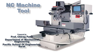
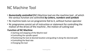
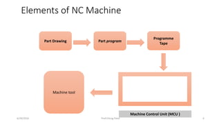
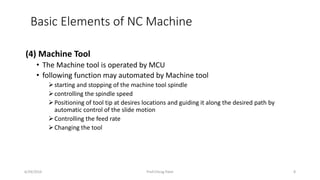
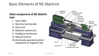
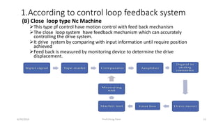
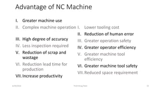

NC machines are numerically controlled machine tools that are programmed to automatically perform manufacturing operations. The key elements of an NC machine include the part drawing and program, program tape, machine control unit (MCU), and machine tool. The MCU reads and interprets the NC program from the tape or file to control the machine tool's functions like positioning the tool, controlling feed rate and spindle speed, and changing tools. NC machines offer advantages like increased accuracy and productivity compared to manual machine tools.