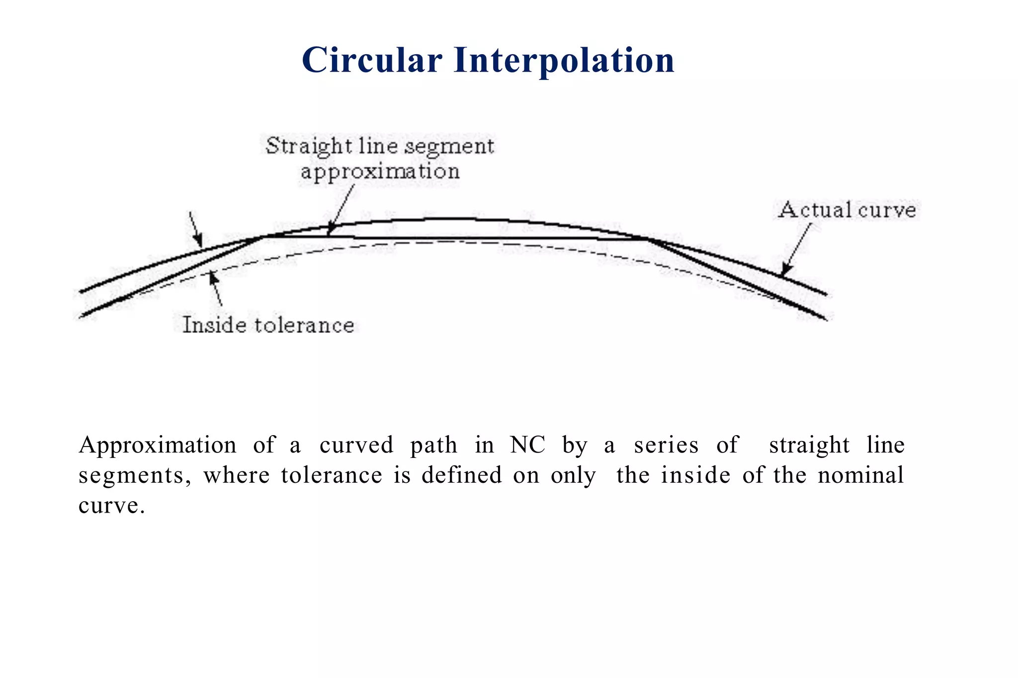
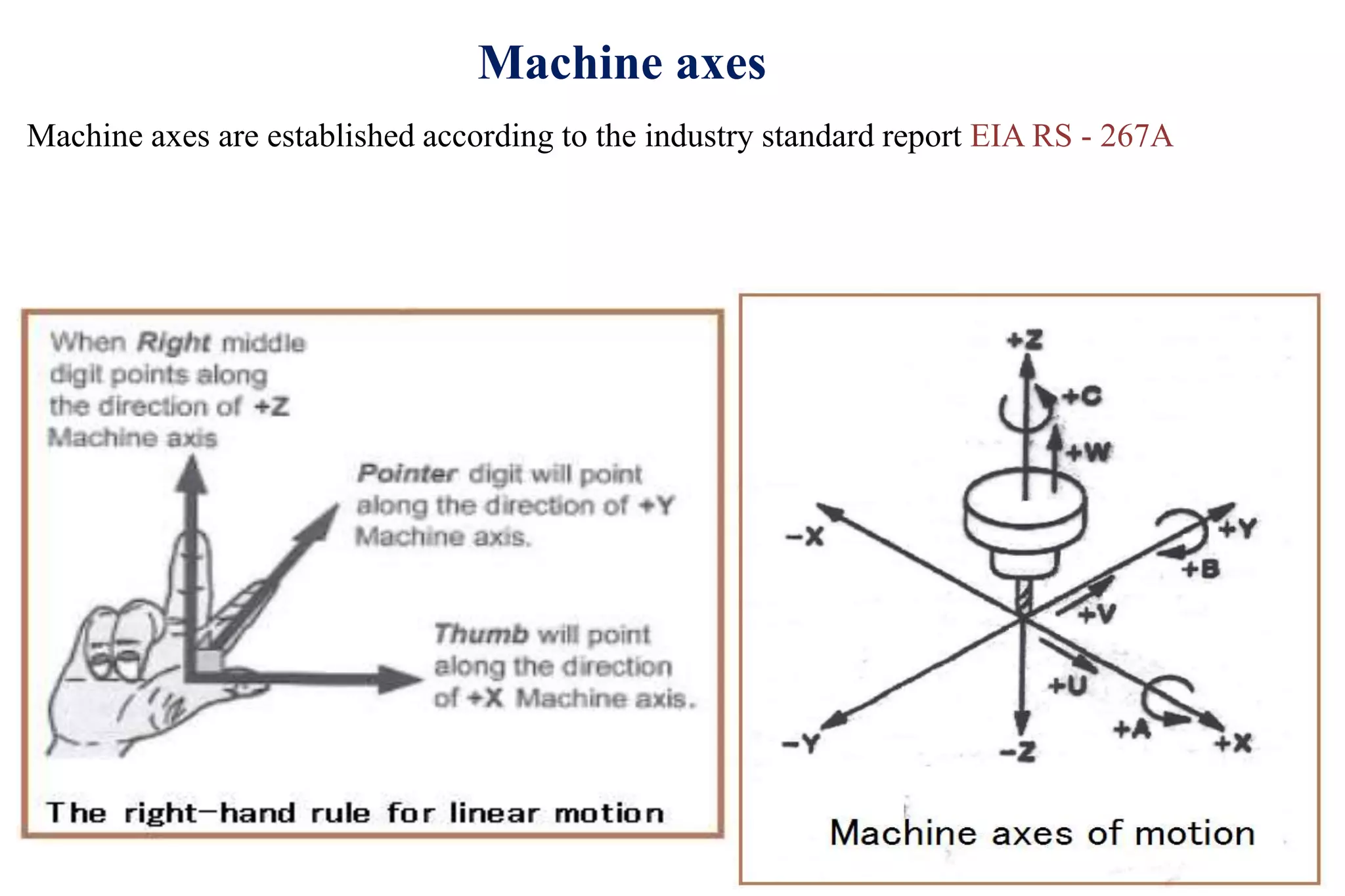
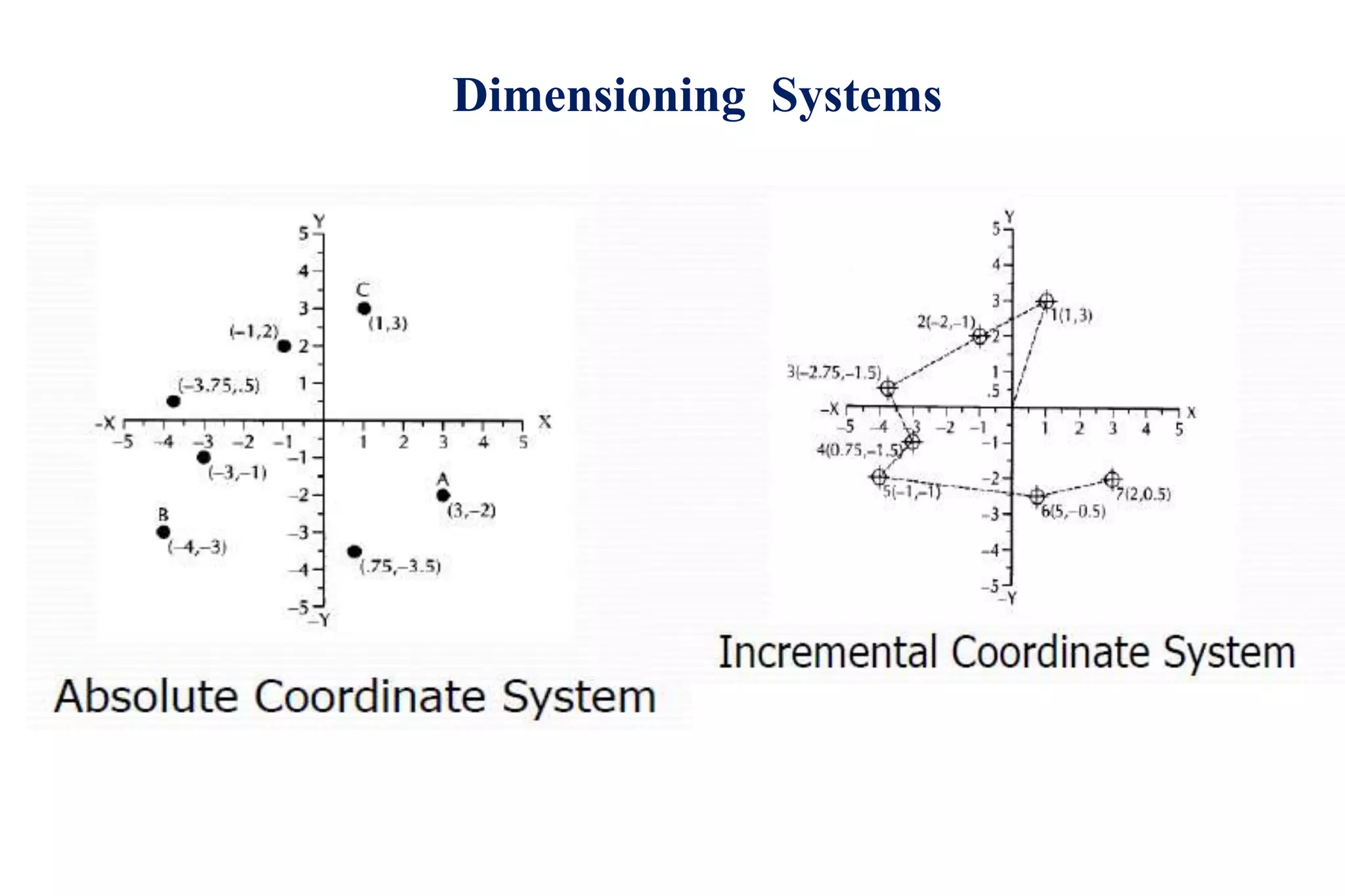
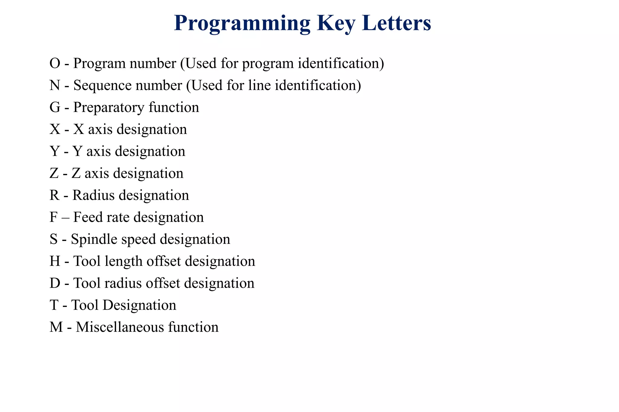
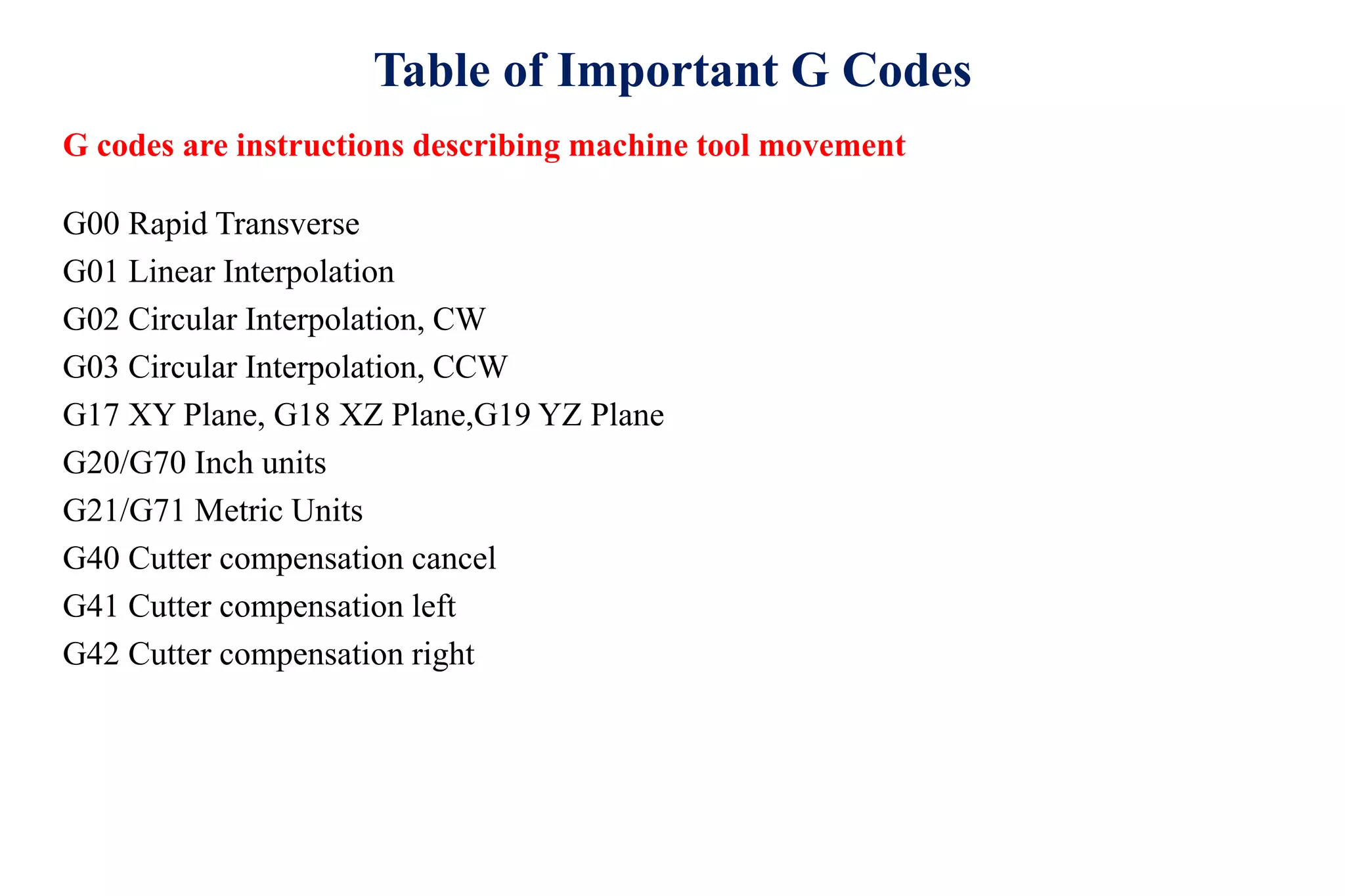
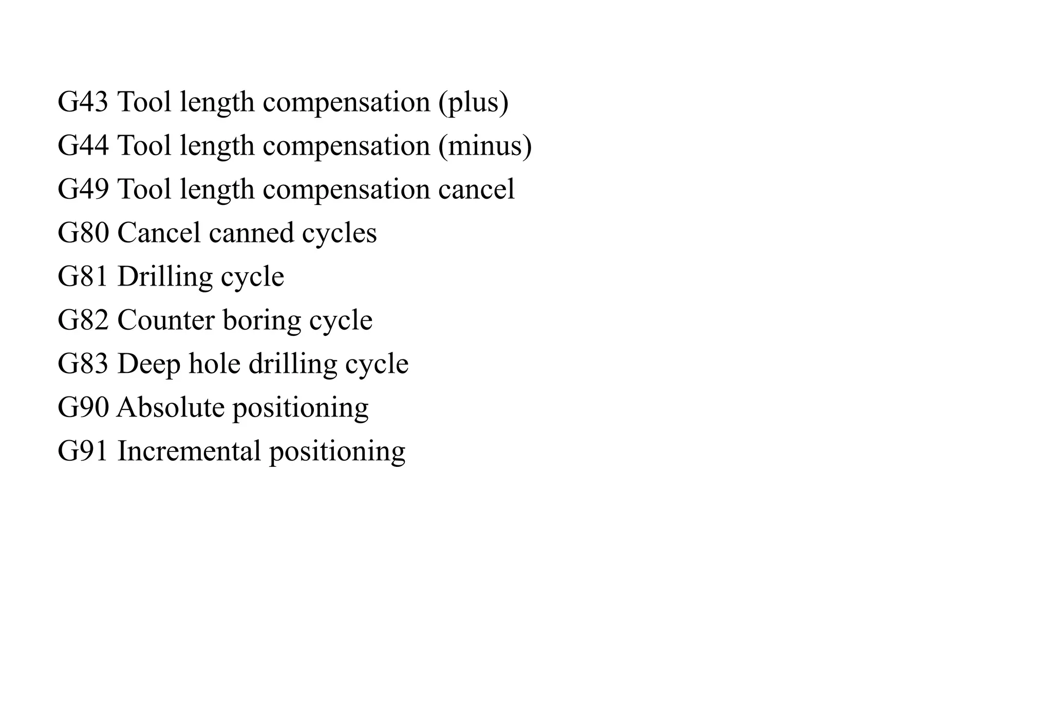
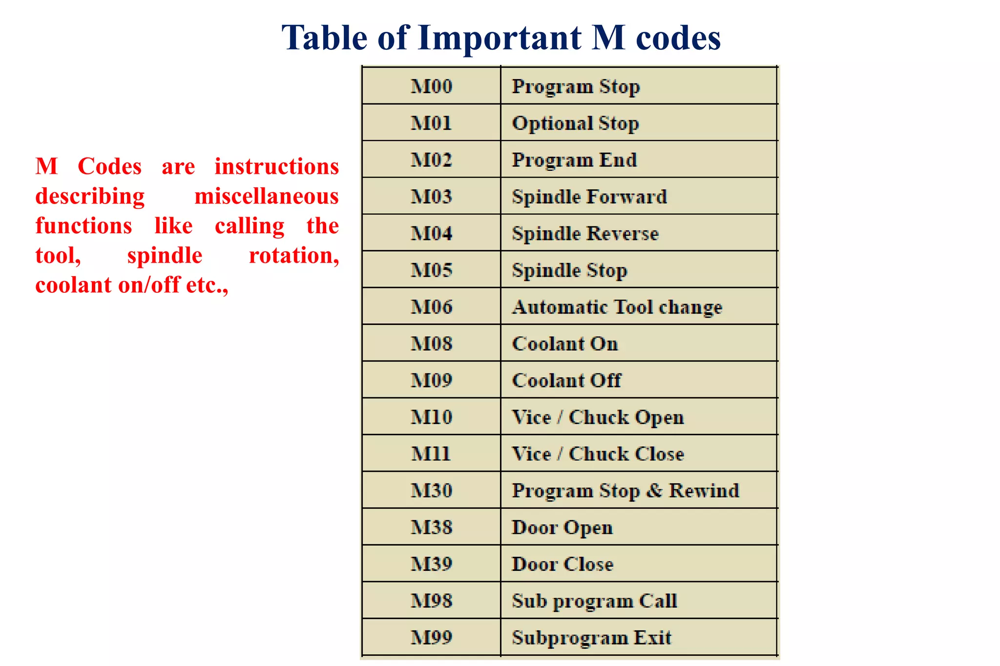
Interpolation Methods
1.Linear interpolation
Straight line between two points in space
2. Circular interpolation
Circular arc defined by starting point, end point, centre or radius, and direction.
3. Helical interpolation
Circular plus linear motion
4. Parabolic and cubic interpolation
Free form curves using higher order equations
Circular Interpolation
Approximation of a curved path in NC by a series of straight line segments,
where tolerance is defined on only the outside of the nominal curve.
Circular Interpolation
Approximation of a curved path in NC by a series of straight line segments,
where tolerance is defined on both the inside and outside of the nominal
curve.
Circular Interpolation
Approximation of a curved path in NC by a series of straight line
segments, where tolerance is defined on only the inside of the nominal
curve.
Machine axes
Machine axes are established according to the industry standard report EIA RS - 267A
Axes configuration
 X axes moves from right to left as you face the machine
 Y axes move toward and away from you
 The Z axes is the spindle movement up and down spindle .
 A move toward work is Z(-Z)
 A move away from work is Z(+ Z)
Dimensioning Systems
CNC Programming
 Programming consists of a series of instructions in form of letter codes
Preparatory Codes:
 G codes- Initial machining setup and establishing operating conditions
 N codes- specify program line number to executed by the MCU
 Axis Codes: X,Y,Z - Used to specify motion of the slide along X, Y, Z direction
 Feed and Speed Codes: F and S- Specify feed and spindle speed
 Tool codes: T – specify tool number
Miscellaneous codes – M codes For coolant control and other activities
Programming Key Letters
O - Program number (Used for program identification)
N - Sequence number (Used for line identification)
G - Preparatory function
X - X axis designation
Y - Y axis designation
Z - Z axis designation
R - Radius designation
F – Feed rate designation
S - Spindle speed designation
H - Tool length offset designation
D - Tool radius offset designation
T - Tool Designation
M - Miscellaneous function
Table of Important G Codes
G00 Rapid Transverse
G01 Linear Interpolation
G02 Circular Interpolation, CW
G03 Circular Interpolation, CCW
G17 XY Plane, G18 XZ Plane,G19 YZ Plane
G20/G70 Inch units
G21/G71 Metric Units
G40 Cutter compensation cancel
G41 Cutter compensation left
G42 Cutter compensation right
G codes are instructions describing machine tool movement
G43 Tool length compensation (plus)
G44 Tool length compensation (minus)
G49 Tool length compensation cancel
G80 Cancel canned cycles
G81 Drilling cycle
G82 Counter boring cycle
G83 Deep hole drilling cycle
G90 Absolute positioning
G91 Incremental positioning
Table of Important M codes
M Codes are instructions
describing miscellaneous
functions like calling the
tool, spindle rotation,
coolant on/off etc.,
Z
X
Part Program
T0101
G97 S500 M03
G01 X25 G95 F0.3
G01 Z-7.5
G01 X40 Z-15
G01 Z-25
G01 X60 Z-35
G40 G00 X200 Z100
CNC Milling example
G90 G71
T1 M6
G92 X-100 Y86 Z95
G00 X0 Y0 S2500 M3
Z12.5
G01 Z-12.5 F150
X-20 Y30
G02 X10 Y100 R80
G01 X140 Y60
G02 X150 Y0 R50
G01 X0 Y0
G00 Z12.5
G91 G28 Z0 M5
G91 G28 X0 Y0
M30
G17 G71 G90 G94 G54
T1 L90
G00 Z5 D5 M03 S500 X20 Y90
G01 Z-2 F50
G02 X60 Y-50 R40
G03 X80 Y-50 R20
G00 Z100
M30
Considering Extreme Left Top Corner(of rectangle) to be as origin
THANK YOU

Interpolations

  • 1.
    Interpolation Methods 1.Linear interpolation Straightline between two points in space 2. Circular interpolation Circular arc defined by starting point, end point, centre or radius, and direction. 3. Helical interpolation Circular plus linear motion 4. Parabolic and cubic interpolation Free form curves using higher order equations
  • 2.
    Circular Interpolation Approximation ofa curved path in NC by a series of straight line segments, where tolerance is defined on only the outside of the nominal curve.
  • 3.
    Circular Interpolation Approximation ofa curved path in NC by a series of straight line segments, where tolerance is defined on both the inside and outside of the nominal curve.
  • 4.
    Circular Interpolation Approximation ofa curved path in NC by a series of straight line segments, where tolerance is defined on only the inside of the nominal curve.
  • 5.
    Machine axes Machine axesare established according to the industry standard report EIA RS - 267A
  • 6.
    Axes configuration  Xaxes moves from right to left as you face the machine  Y axes move toward and away from you  The Z axes is the spindle movement up and down spindle .  A move toward work is Z(-Z)  A move away from work is Z(+ Z)
  • 7.
  • 8.
    CNC Programming  Programmingconsists of a series of instructions in form of letter codes Preparatory Codes:  G codes- Initial machining setup and establishing operating conditions  N codes- specify program line number to executed by the MCU
  • 9.
     Axis Codes:X,Y,Z - Used to specify motion of the slide along X, Y, Z direction  Feed and Speed Codes: F and S- Specify feed and spindle speed  Tool codes: T – specify tool number Miscellaneous codes – M codes For coolant control and other activities
  • 10.
    Programming Key Letters O- Program number (Used for program identification) N - Sequence number (Used for line identification) G - Preparatory function X - X axis designation Y - Y axis designation Z - Z axis designation R - Radius designation F – Feed rate designation S - Spindle speed designation H - Tool length offset designation D - Tool radius offset designation T - Tool Designation M - Miscellaneous function
  • 11.
    Table of ImportantG Codes G00 Rapid Transverse G01 Linear Interpolation G02 Circular Interpolation, CW G03 Circular Interpolation, CCW G17 XY Plane, G18 XZ Plane,G19 YZ Plane G20/G70 Inch units G21/G71 Metric Units G40 Cutter compensation cancel G41 Cutter compensation left G42 Cutter compensation right G codes are instructions describing machine tool movement
  • 12.
    G43 Tool lengthcompensation (plus) G44 Tool length compensation (minus) G49 Tool length compensation cancel G80 Cancel canned cycles G81 Drilling cycle G82 Counter boring cycle G83 Deep hole drilling cycle G90 Absolute positioning G91 Incremental positioning
  • 13.
    Table of ImportantM codes M Codes are instructions describing miscellaneous functions like calling the tool, spindle rotation, coolant on/off etc.,
  • 14.
  • 15.
    Part Program T0101 G97 S500M03 G01 X25 G95 F0.3 G01 Z-7.5 G01 X40 Z-15 G01 Z-25 G01 X60 Z-35 G40 G00 X200 Z100
  • 16.
    CNC Milling example G90G71 T1 M6 G92 X-100 Y86 Z95 G00 X0 Y0 S2500 M3 Z12.5 G01 Z-12.5 F150 X-20 Y30 G02 X10 Y100 R80 G01 X140 Y60 G02 X150 Y0 R50 G01 X0 Y0 G00 Z12.5 G91 G28 Z0 M5 G91 G28 X0 Y0 M30
  • 17.
    G17 G71 G90G94 G54 T1 L90 G00 Z5 D5 M03 S500 X20 Y90 G01 Z-2 F50 G02 X60 Y-50 R40 G03 X80 Y-50 R20 G00 Z100 M30 Considering Extreme Left Top Corner(of rectangle) to be as origin
  • 18.