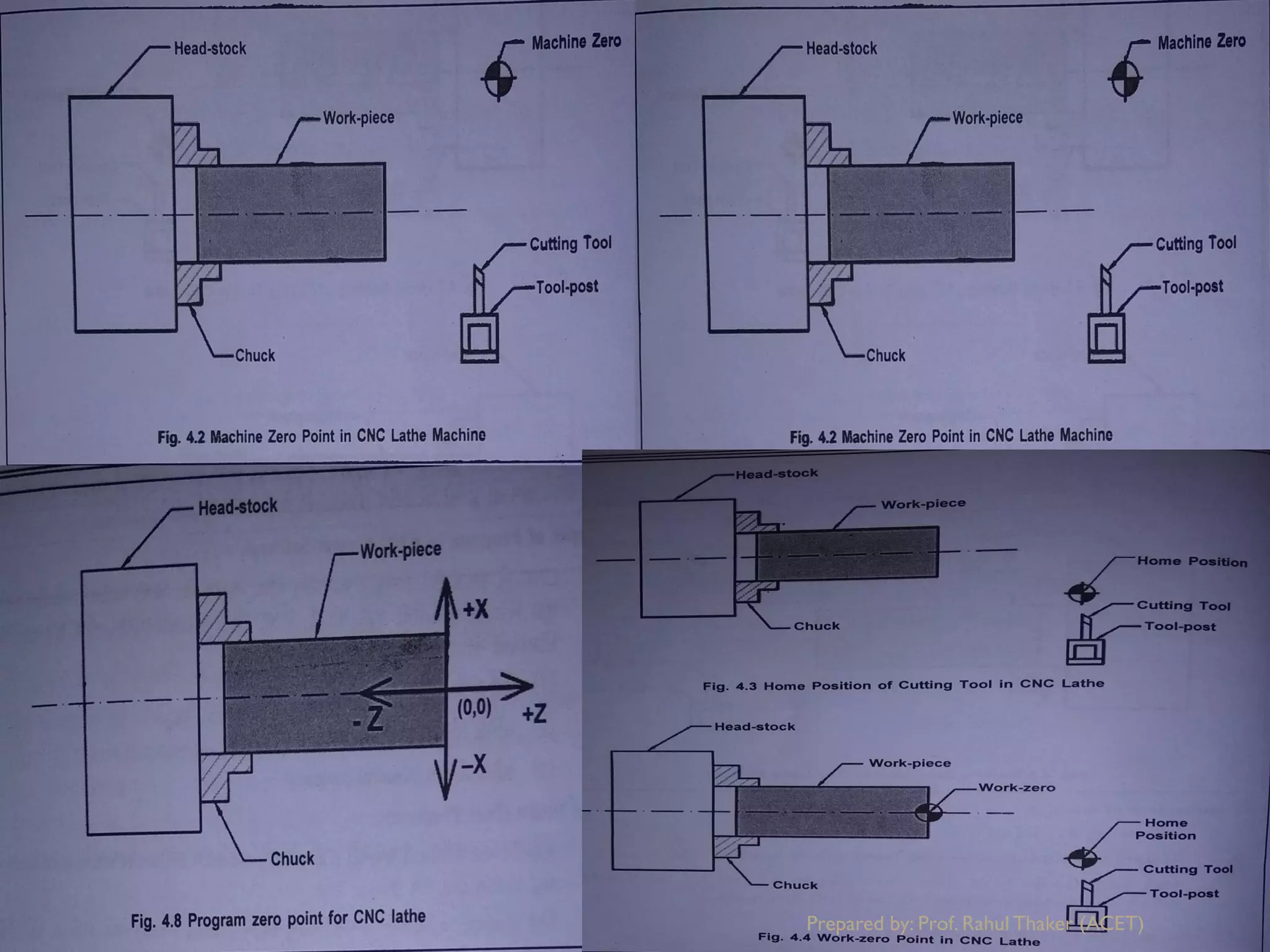
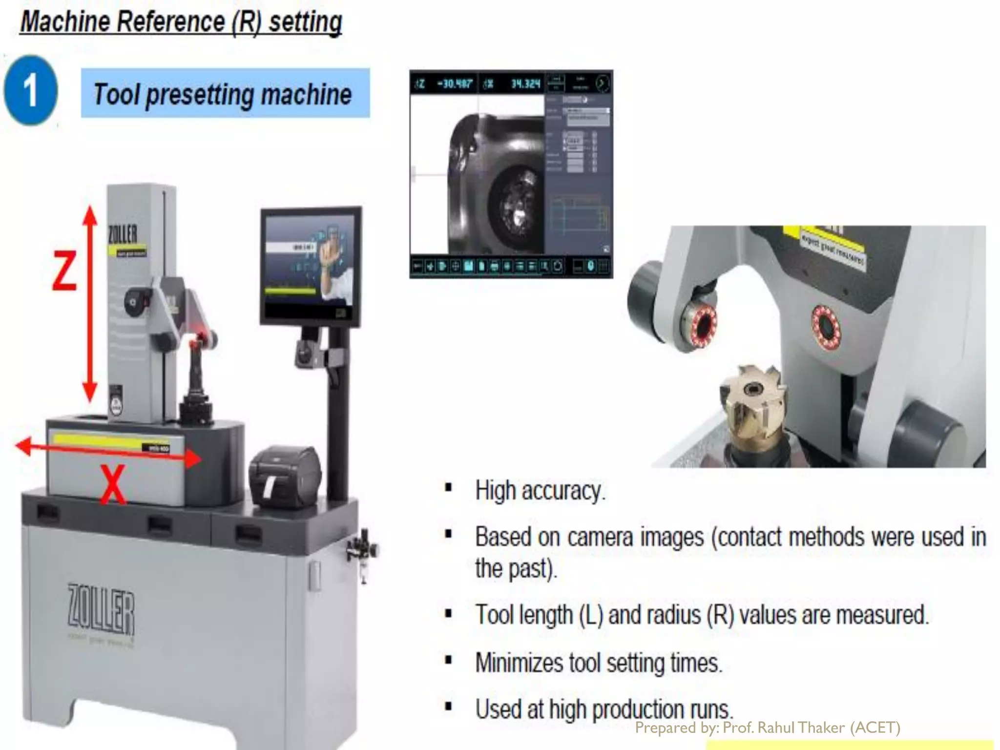
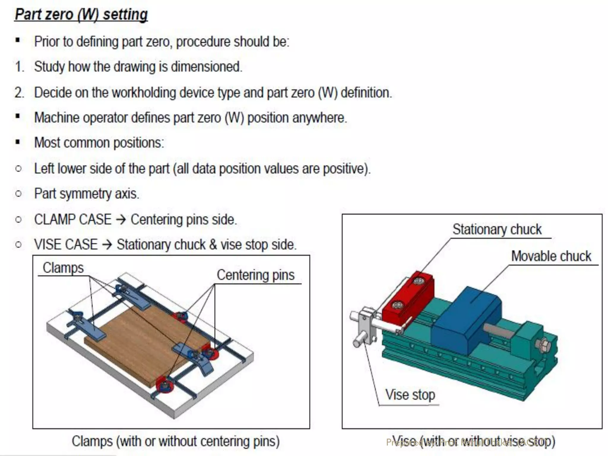
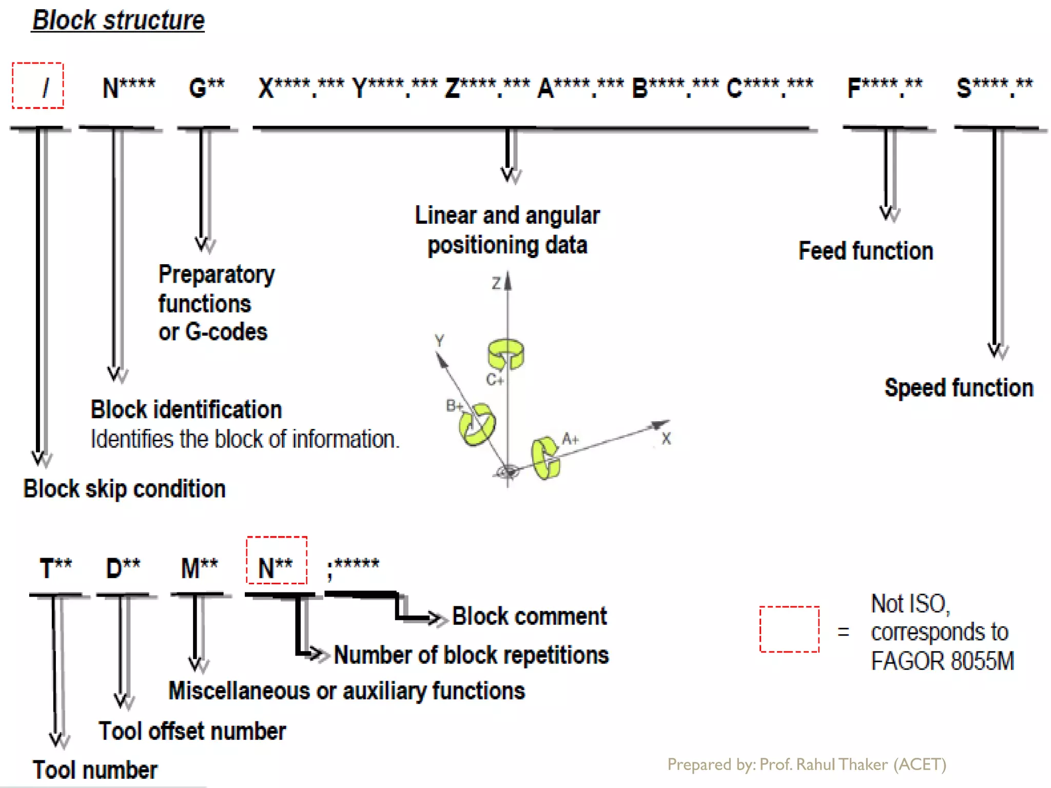
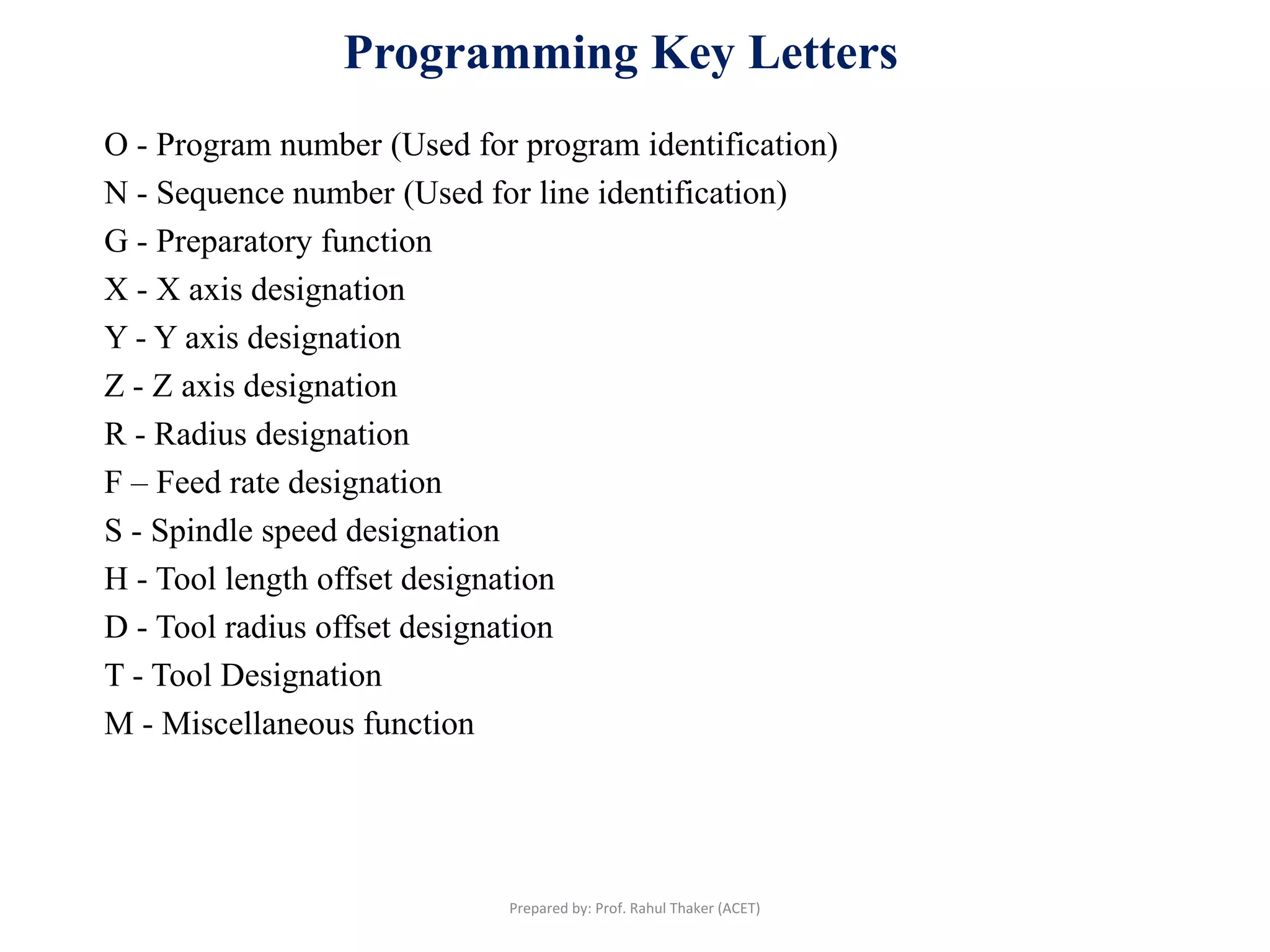
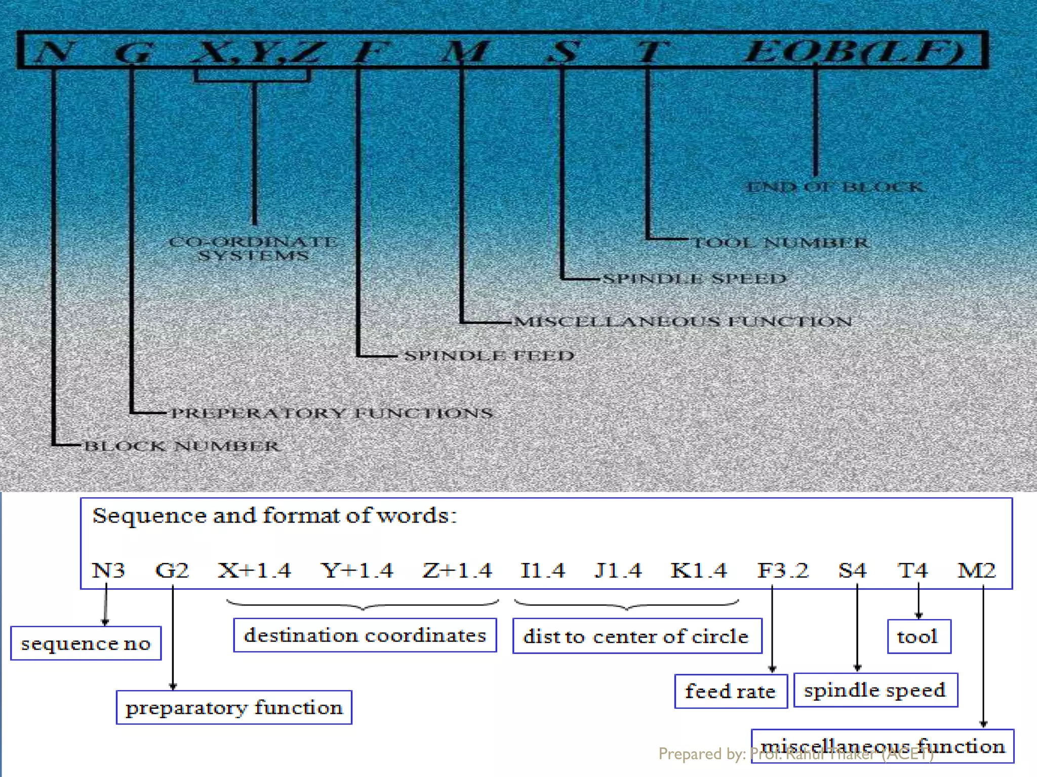
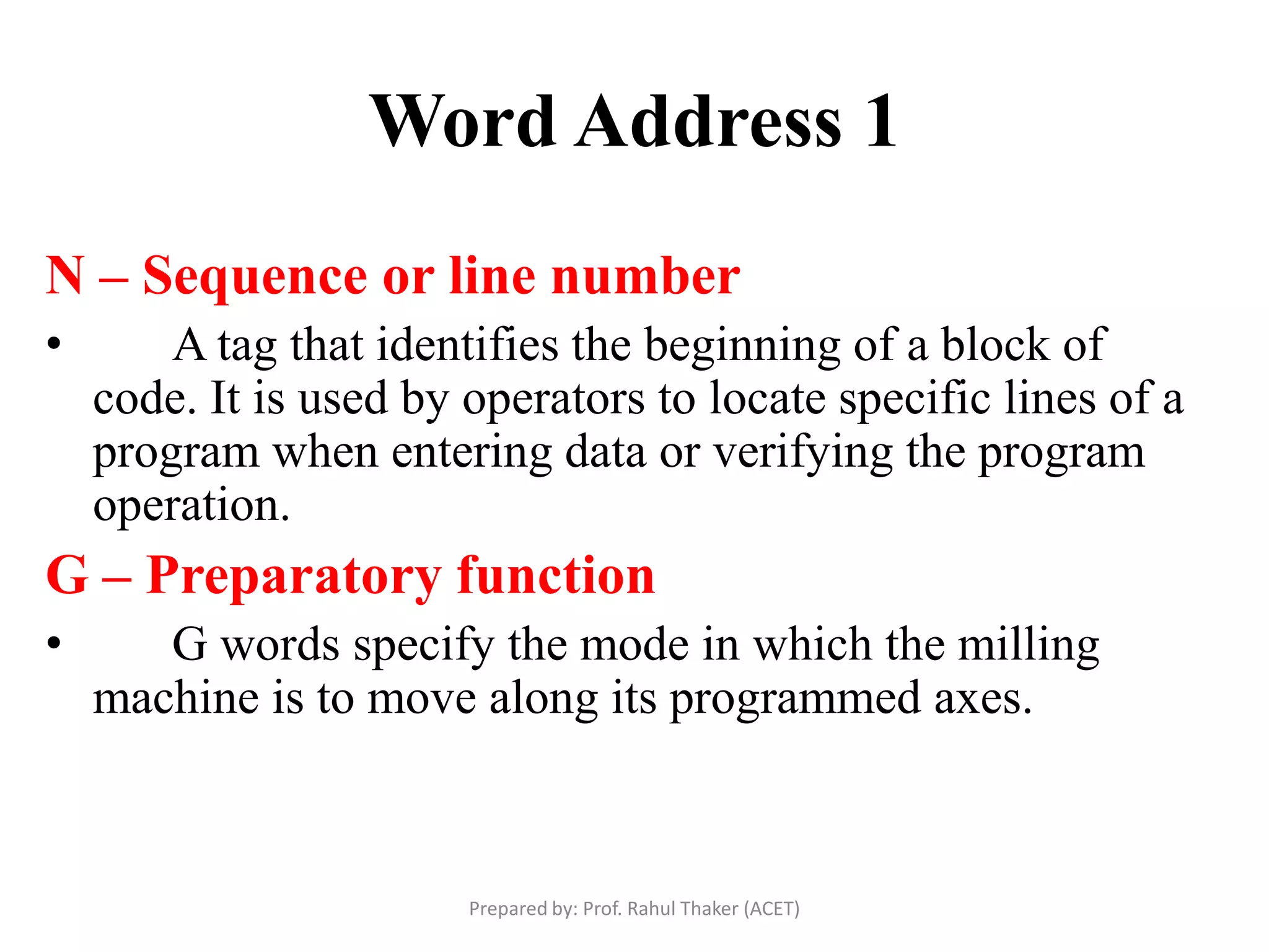
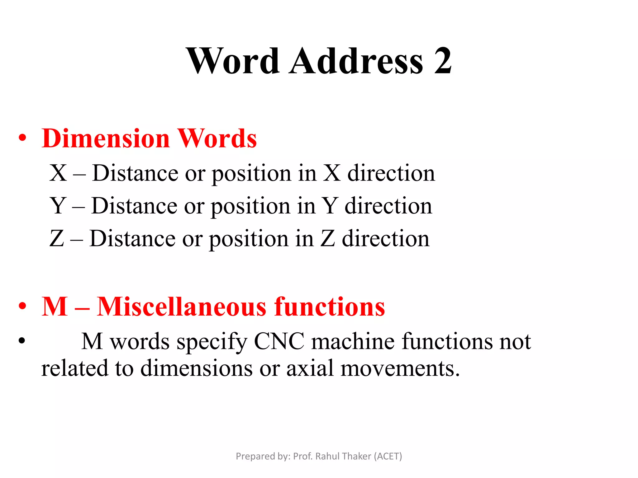
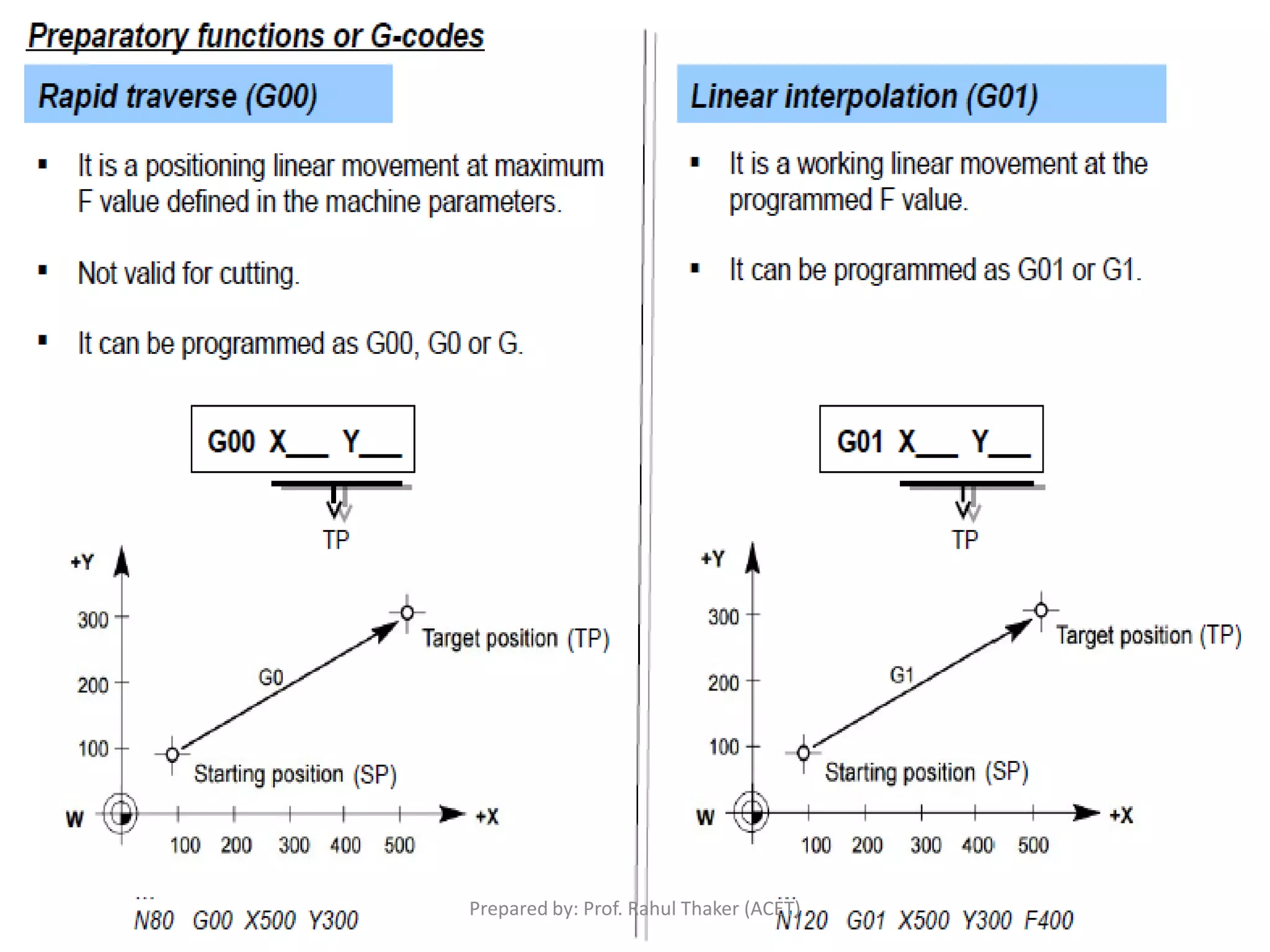
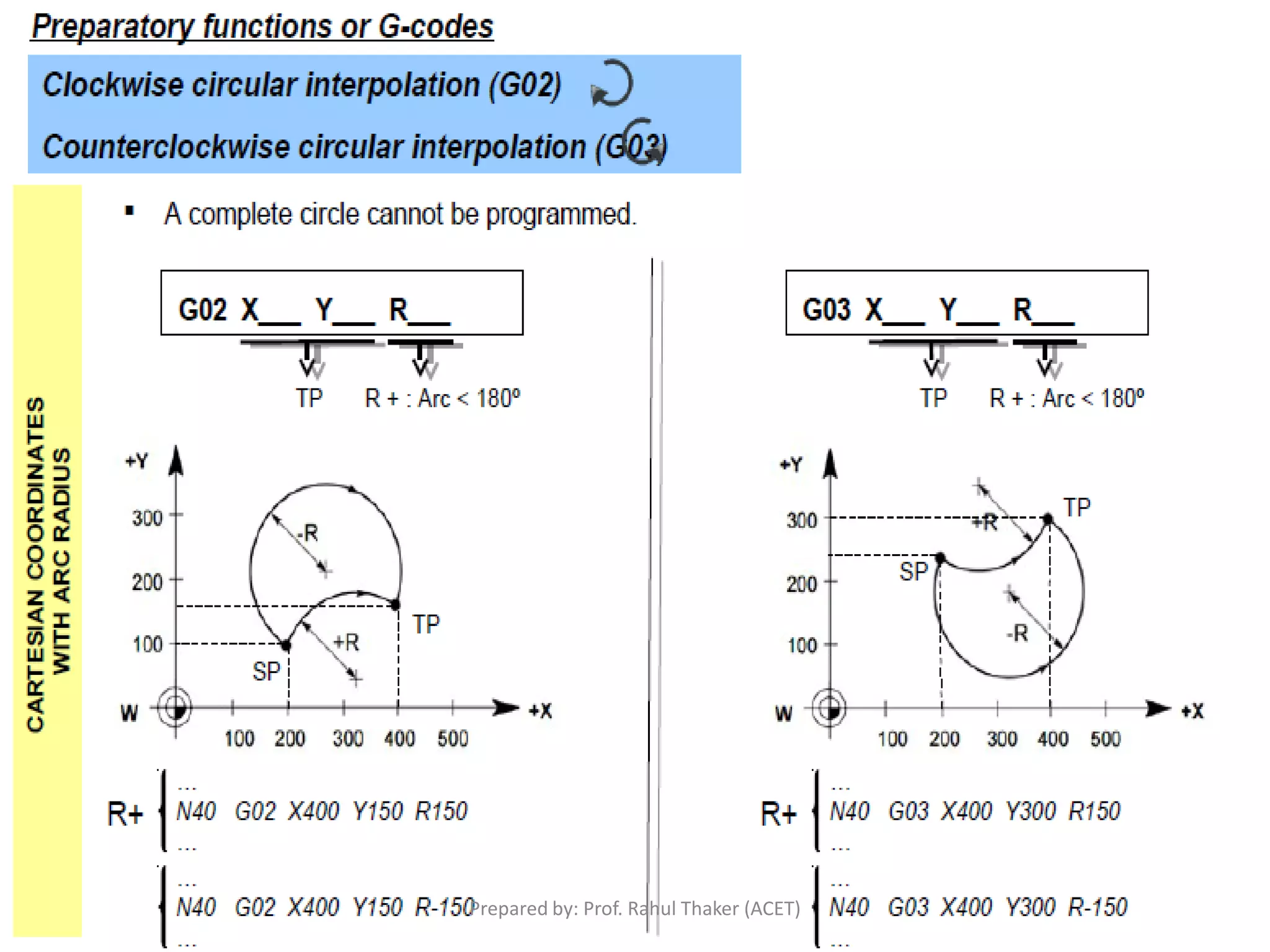
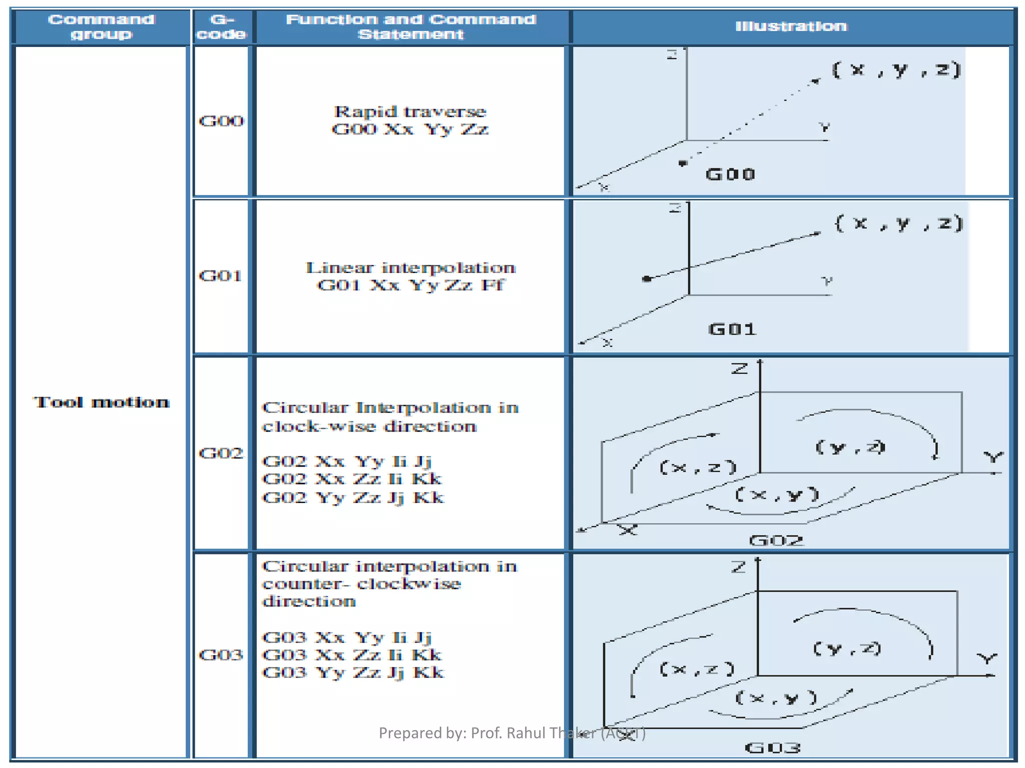
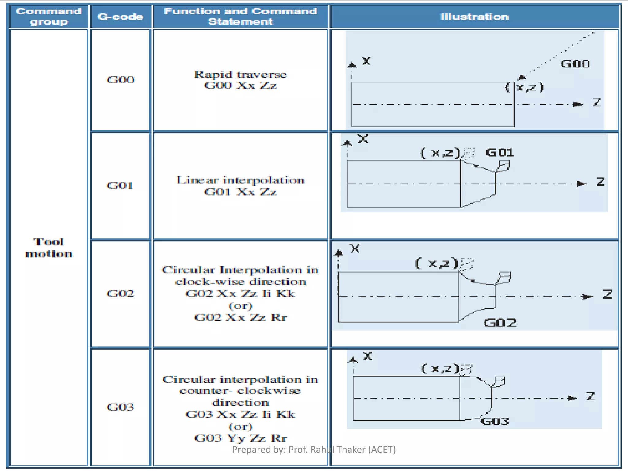
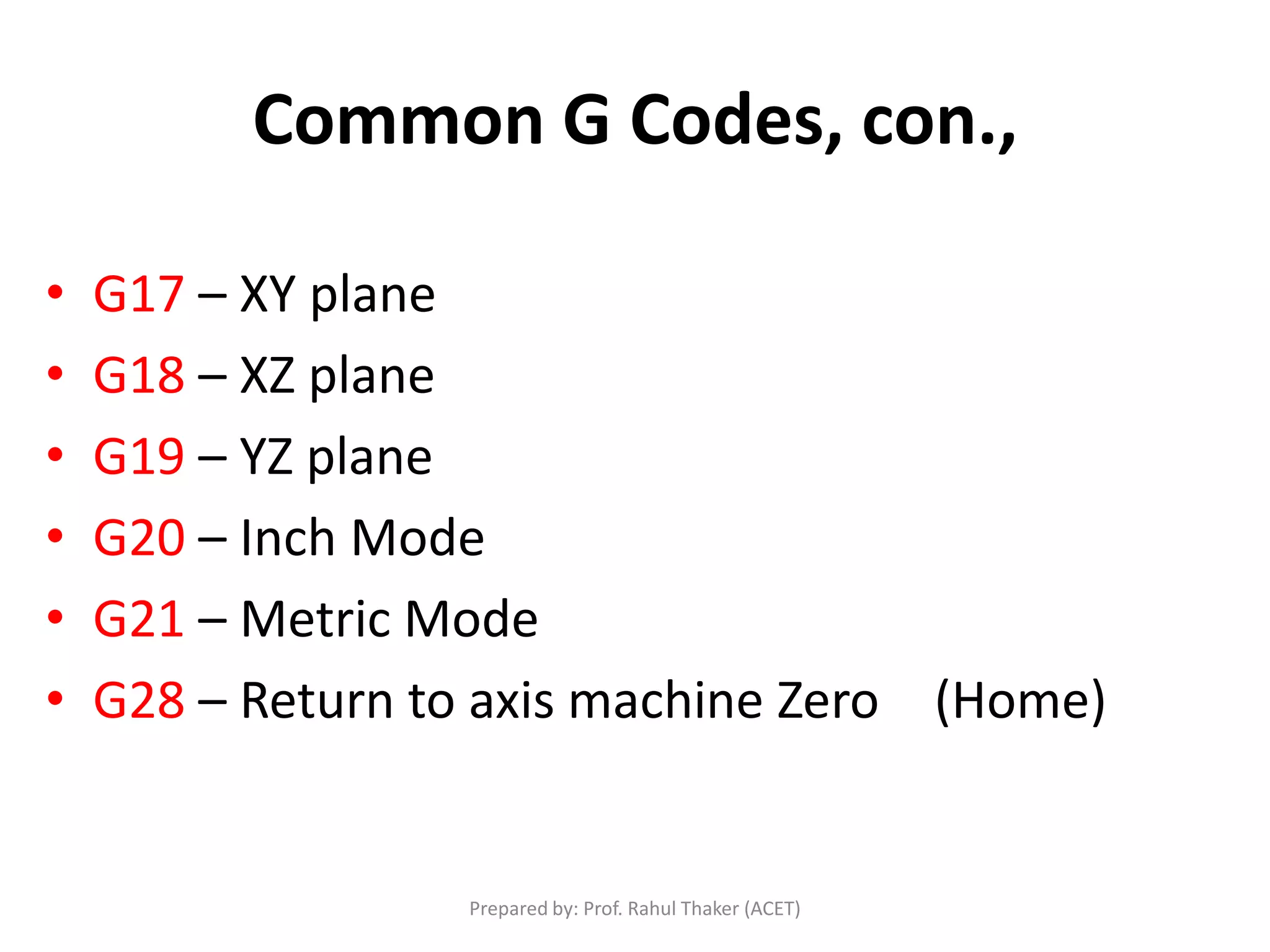
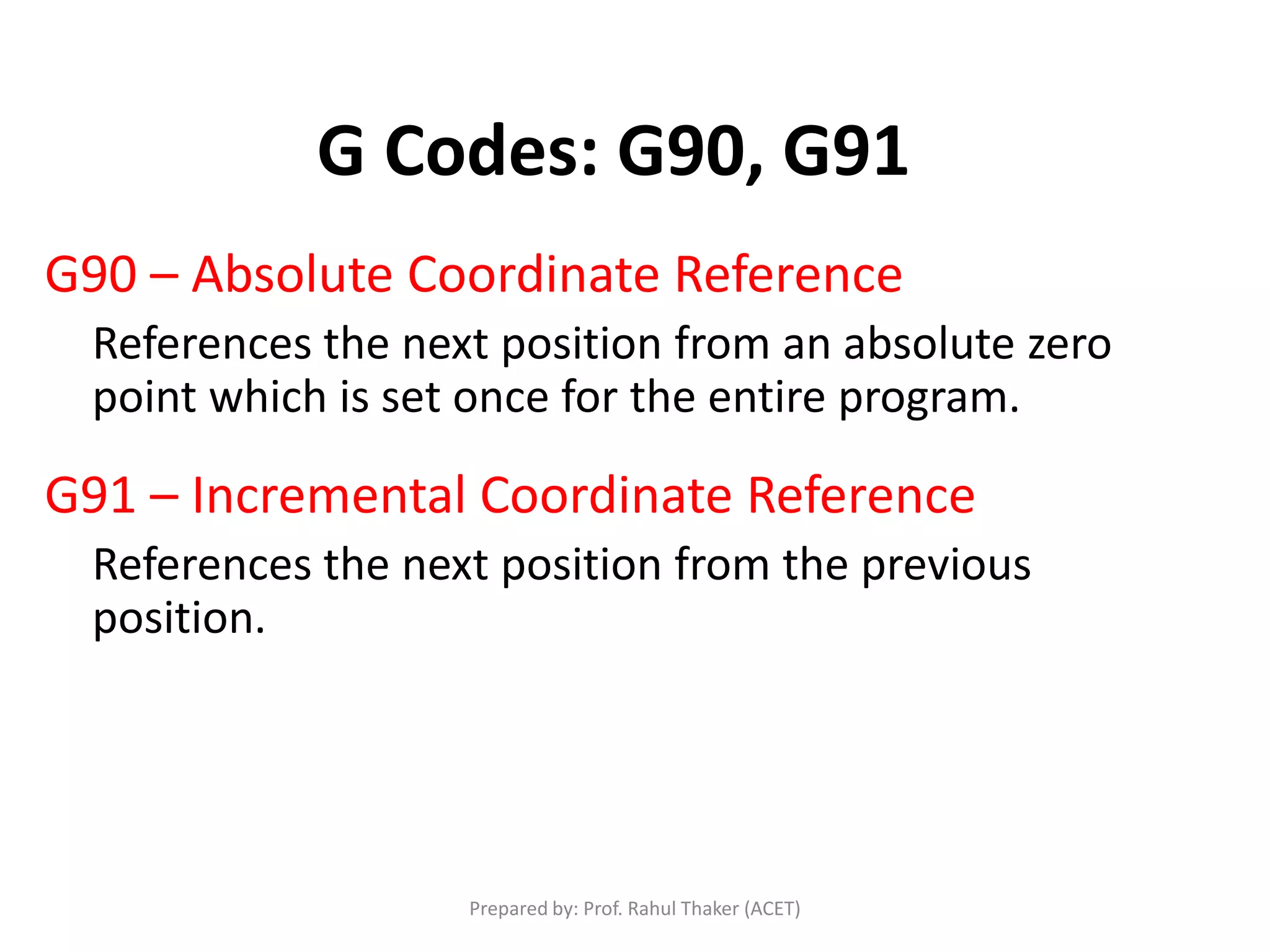
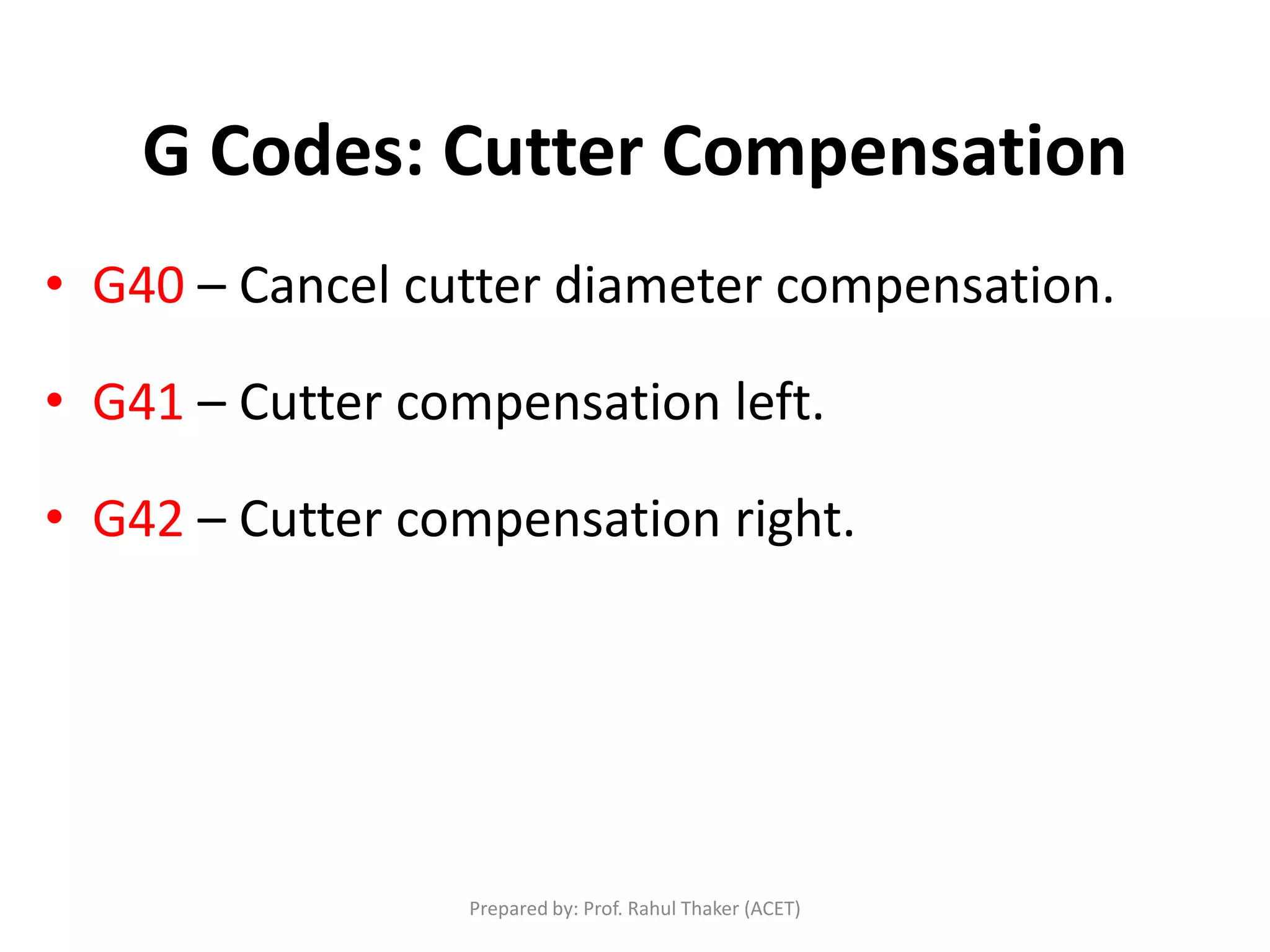
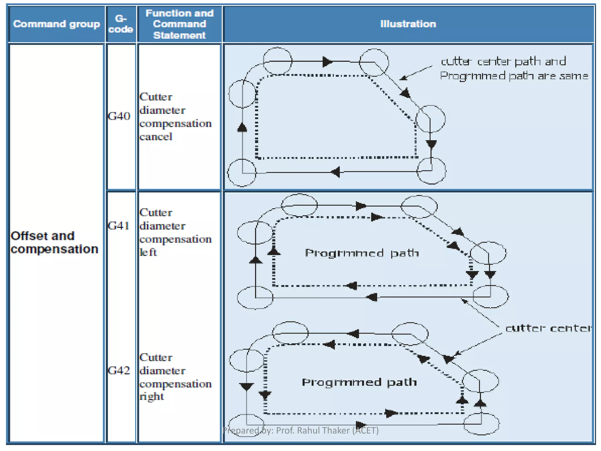
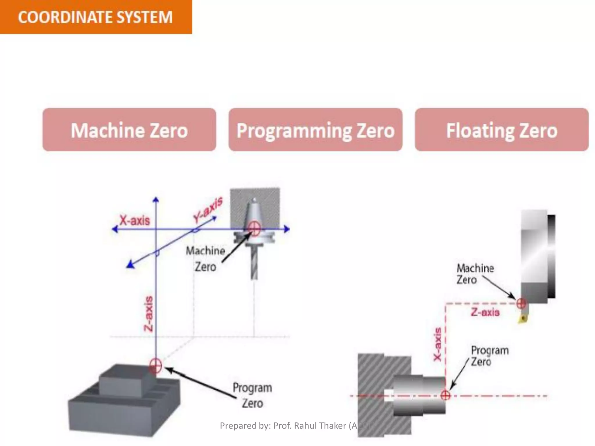
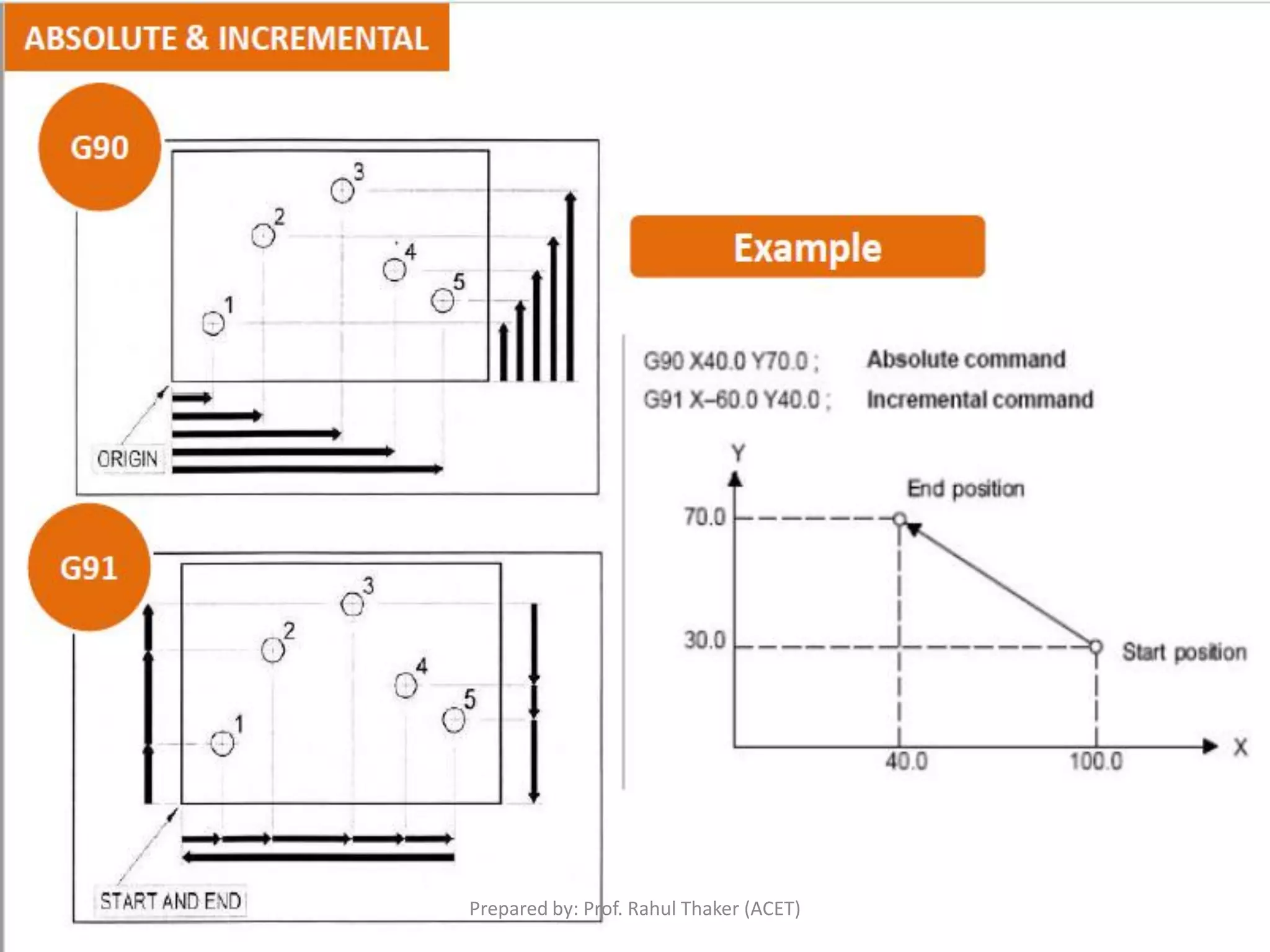
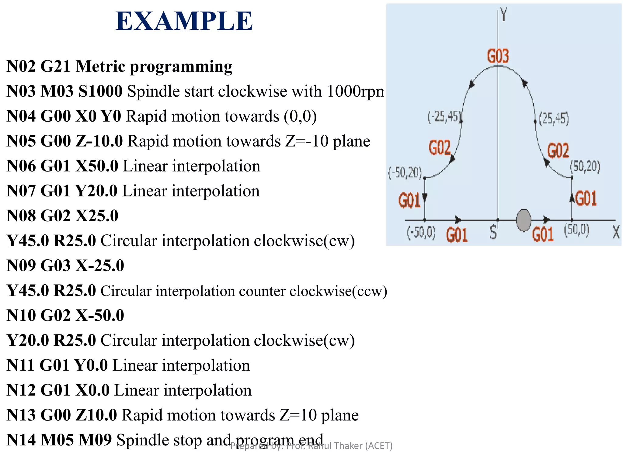
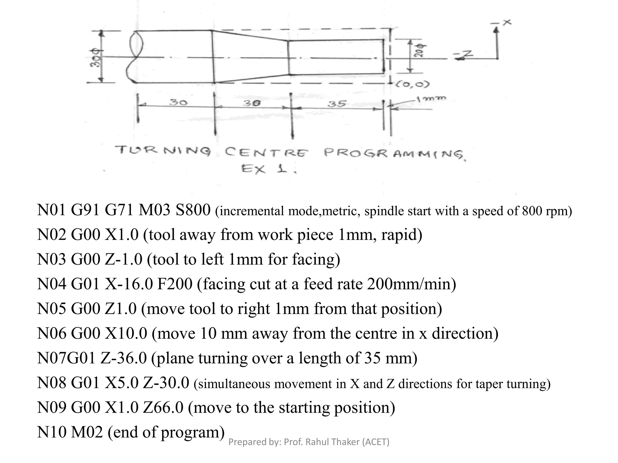
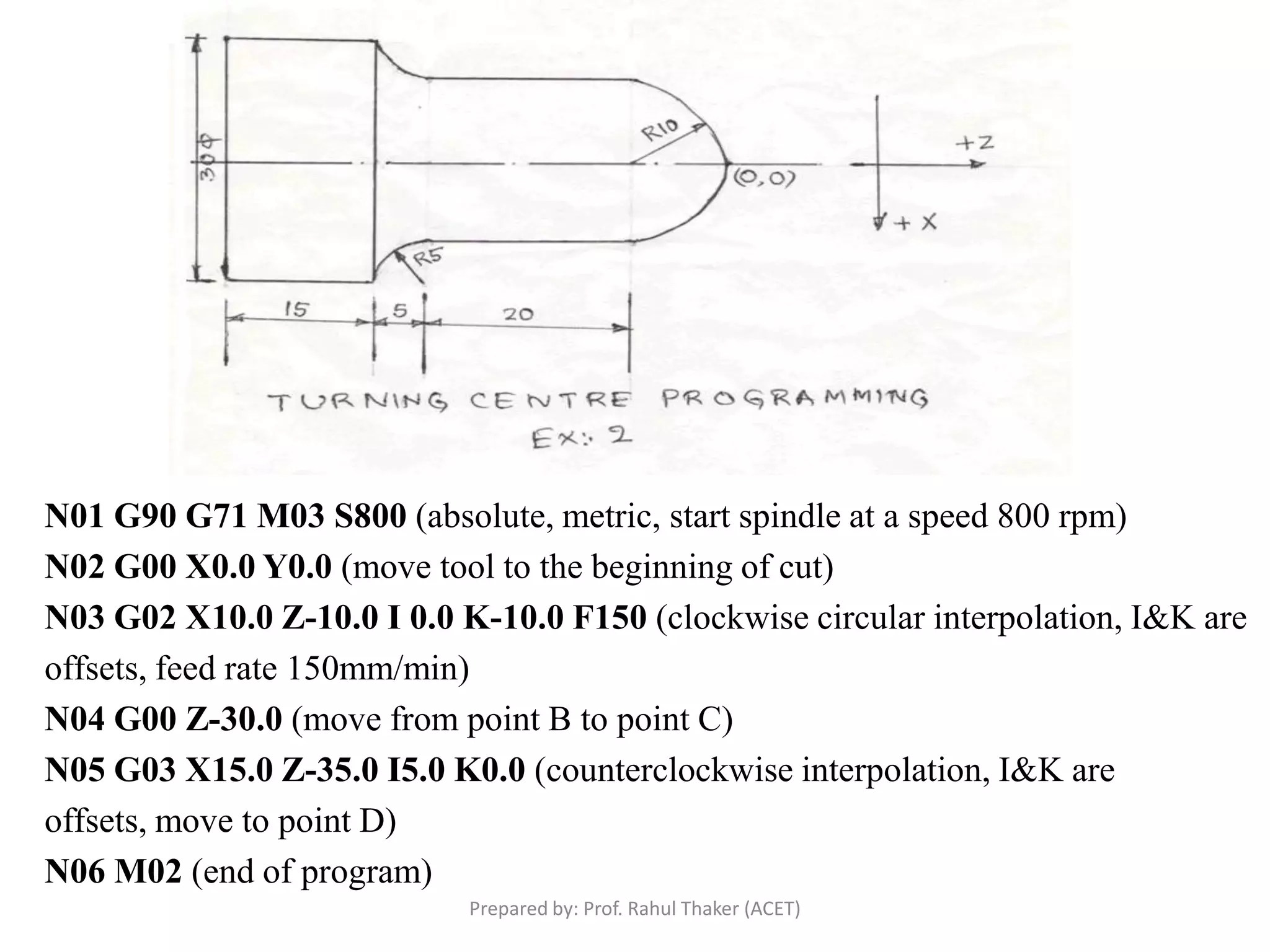
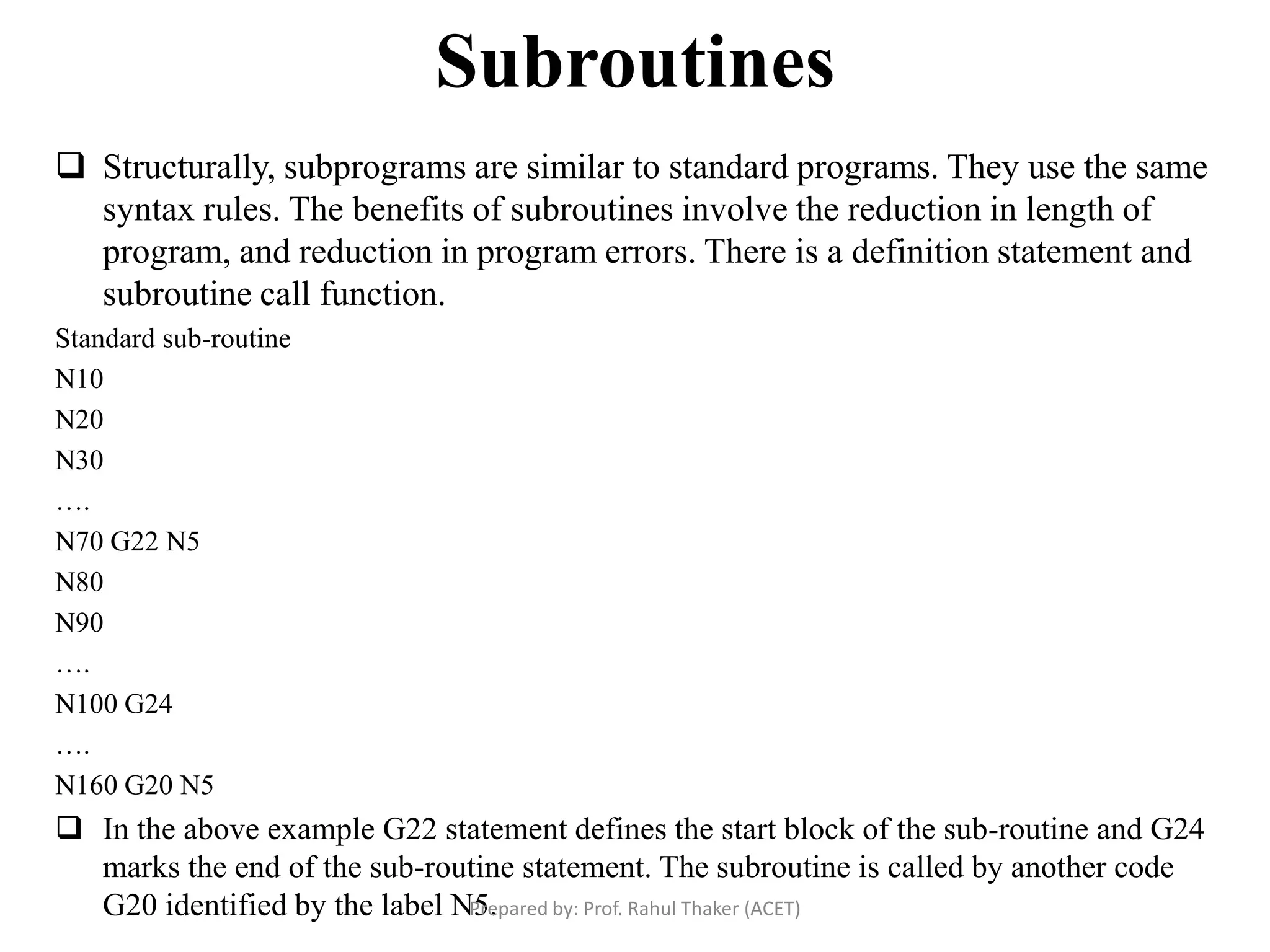
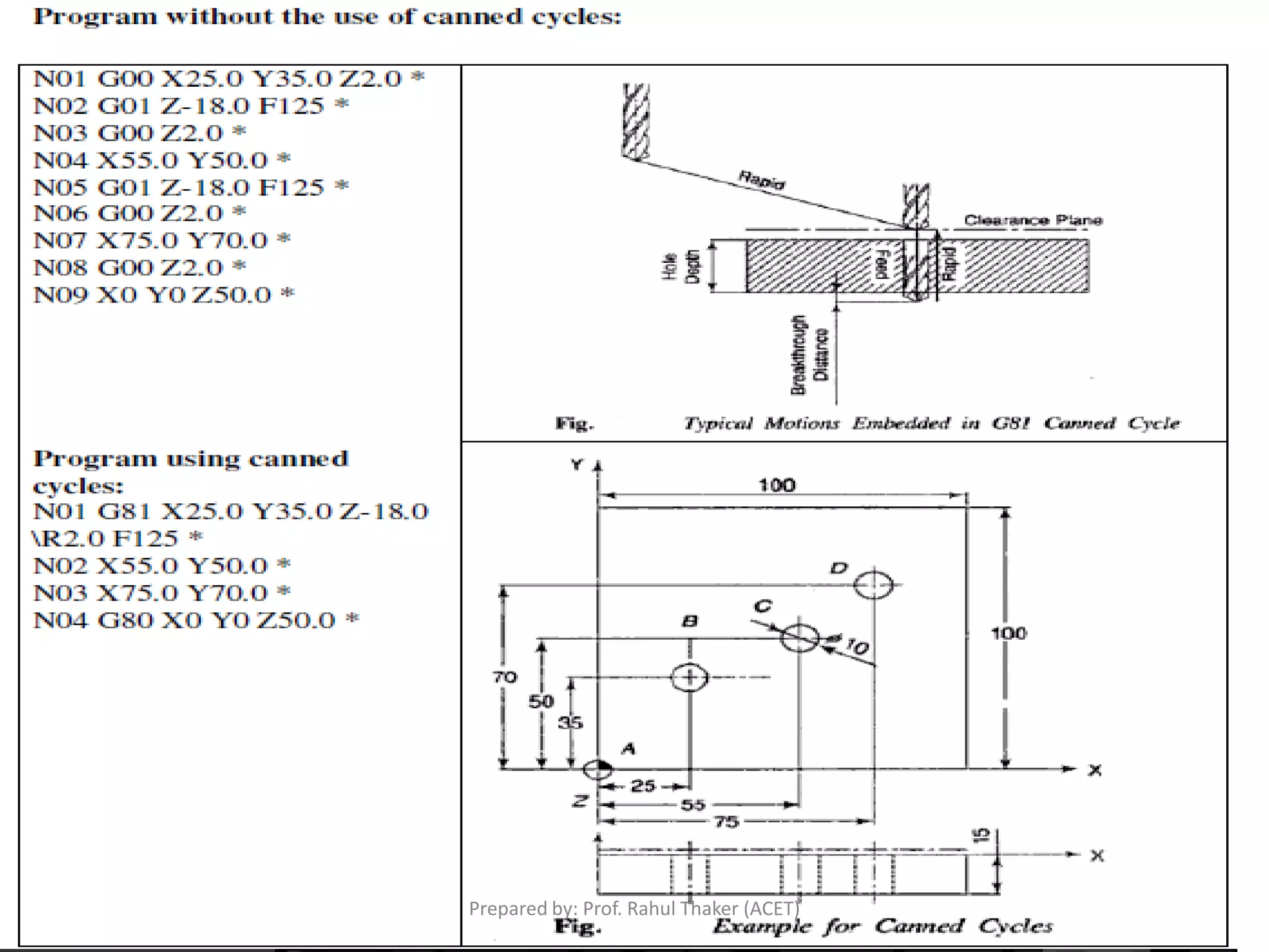
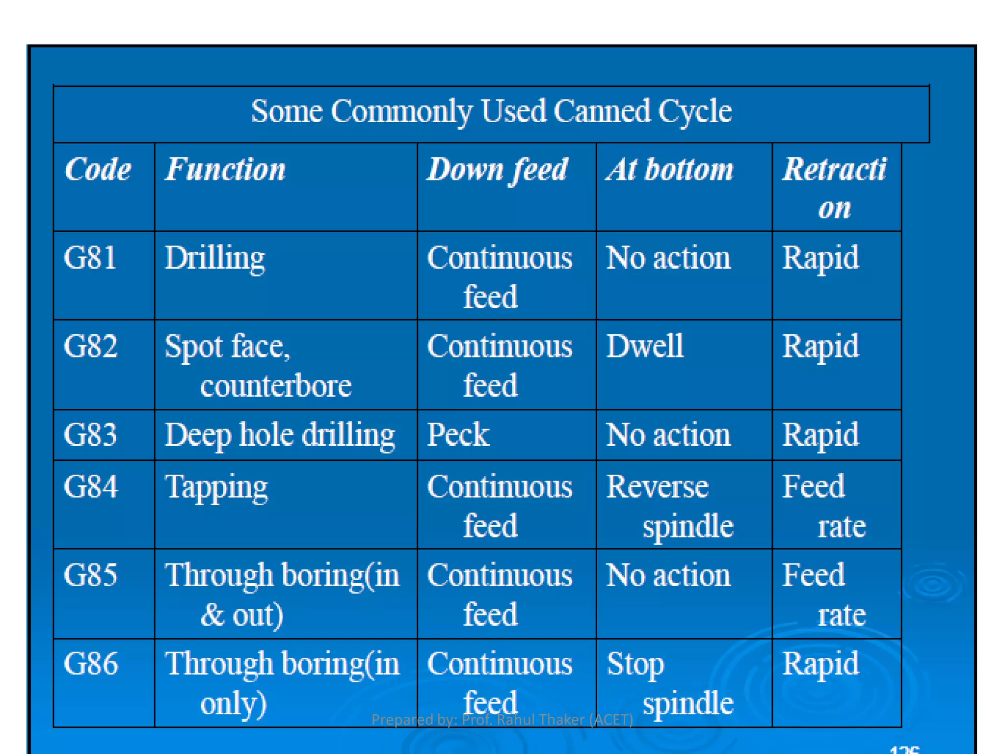
The document discusses CNC part programming and provides information on:
- Reference systems used in CNC programming including machine zero, part zero, and machine reference point.
- Key elements that make up a CNC program including preparatory functions, dimensions, feed rates, spindle speeds, and tool information.
- Common G-codes (preparatory functions) and M-codes (miscellaneous functions) used in programming.
- Programming methods including absolute and incremental coordinate systems, cutter compensation, and subroutines.
- Canned cycles which are preprogrammed sequences that save time in programming repetitive motions.
This describes the mechanism of Computer Numerical Control along with its types, control system, motion system, Programming of CNC, G codes, Part programming, adaptive control machining etc.
Modern precision manufacturing demands extreme dimensional accuracy and surface finish.Such performance is very difficult to achieve manually, if not impossible, even with expert operators. In cases where it is possible, it takes much higher time due to the need for frequent dimensional measurement to prevent overcutting. It is thus obvious that automated motion control would replace manual “handwheel” control in modern manufacturing. Development of computer numerically controlled (CNC) machines has also made possible the automation of the machining processes with flexibility to handle production of small to medium batch of parts. In the 1940s when the U.S. Air Force perceived the need to manufacture complex parts for highspeed aircraft. This led to the development of computer-based automatic machine tool controls also known as the Numerical Control (NC) systems. Commercial production of NC machine tools started around the fifties and sixties around the world. Note that at this time the microprocessor has not yet been invented. Initially, the CNC technology was applied on lathes, milling machines, etc. which could perform a single type of metal cutting operation. Later, attempt was made to handle a variety of workpieces that may require several different types machining operations and to finish them in a single set-up. Thus CNC machining Centres capable of performing multiple operations were developed. To start with, CNC machining centres were developed for machining prismatic components combining operations like milling, drilling, boring and tapping. Gradually machines for manufacturing cylindrical components, called turning centers were developed.
Automatically controlling a machine tool based on a set of pre-programmed machining and movement instructions is known as numerical control, or NC.In a typical NC system the motion and machining instructions and the related numerical data, together called a part program, used to be written on a punched tape. The part program is arranged in the form of blocks of information, each related to a particular operation in a sequence
of operations needed for producing a mechanical component. The punched tape used to be read one block at a time. Each block contained, in a particular syntax, information needed for processing a particular machining instruction such as, the segment length, its cutting speed, feed, etc. These pieces of information were related to the final dimensions of the workpiece (length, width, and radii of circles) and the contour forms (linear, circular, or other) as per the drawing. Based on these dimensions, motion commands were given separately for each axis of motion. Other instructions and related machining parameters, such as cutting speed, feed rate, as well as auxiliary functions related to coolant flow, spindle speed, part clamping, are also provided in part programs depending on manufacturing specifications such as tolerance and surface finish. Punched tapes are mostly obsolete.
Introduction to CNC machine and Hardware. aman1312
Complete detailing of cnc machine and its operations with its required hardware necessary for increasing its Automation and increasing its manufacturing capability. Also increase in complex shape manufacturing.
difference of NC and CNC ,Part programming,Methods of manual part programming,Basic CNC input data,Preparatory Functions ,Miscellaneous Functions,Interpolation:Canned cycles:part programming on component,Tool length compensation,Cutter Radius,Task compensation:Types of media of NC
APT stands for Automatically Programmed Tool. It is a language that defines the tool path with respect to the part
geometry, and often forms the basis for post-processor generated NC files.
Cnc tooling for cnc machine(130670119596)Kushal Shah
we have seen what the NC machine is and its various
parts, it is easier to understand what the CNC machine is. CNC is
the short form for Computer Numerical control. We have seen that
the NC machine works as per the program of instructions fed into
the controller unit of the machine. The CNC machine comprises of
the mini computer or the microcomputer that acts as the controller
unit of the machine. While in the NC machine the program is fed
into the punch cards, in CNC machines the program of instructions
is fed directly into the computer via a small board similar to the
traditional keyboard.
THIS PPT CONTAIN VMC TRAINING AT GHANDHY COLLEGE SURAT. THIS INCLUDE ABOUT CNC MACHINE, AXIS IDENTIFICATIONS, PART PROGRAMMING, G CODES, M CODES,OPERATING OF VMC....SIMPLE DRAWING FOR VMC INCLUDING LINEAR N CIRCULAR INTERPOLATIONS
This presentation is prepared as per syllabus of "COMMUNICATION ANALYSIS AND SKILL DEVELOPMENT PROGRAM (CASP)" prescribed by BOARD OF TECHNICAL EDUCATION, KARNATAKA for 5th sem diploma all branches.
This pptx is prepared by lots of information in websites,Textbooks(Author B
A Srinivas and M R Manjunath),And guidance of our lecturers Srinath V- B.E,FIE & M D Dayanand- B.E . SET Polytechnic, Melukote
cnc, mesin cnc, fanuc, haas, makino, yaskawa, doosan, mesin bubut, mesin milling, mesin tapping, wirecut, mesin press, mesin pabrik, mesin otomotif, sparepart mesin cnc
Pneumatic circuits:
Basic pneumatic circuits, Development of single Actuator Circuits, Development of multiple Actuator Circuits, Cascade method for sequencing
Introduction to Pneumatic Systems:
Basic Requirements for Pneumatic System,Applications, Pneumatic fundamentals, Construction, working principle and operation of pneumatic power transmission system components like Power source, FRL unit, Actuators and control valves like DCV, FCV, PCV, time delay, quick exhaust, twin pressure, shuttle
Hydraulic Valves and Hydraulic System AccessoriesRAHUL THAKER
Hydraulic Valves and Hydraulic System Accessories:
Direction control valves,Pressure control valves, Flow control valves, Non-return valves, Reservoirs,Accumulators, Heating & cooling devices, Hoses. Selection of valves for circuits.
Hydraulic Pumps, Motors and Actuators:
Construction, working principle and operation of rotary & reciprocating pumps like Gear, Vane, Generated-Rotor, Screw, Axial Piston, Radial Piston, Pump characteristics, Linear and Rotary Actuators, Hydrostatic Transmission Systems. Selection of components for applications
System Components, Hydraulic Oils, Fluid Properties and FilterRAHUL THAKER
System Components, Hydraulic Oils, Fluid Properties and Filter:
Hydraulic & Pneumatic Symbols as per ISO/ANSI, Types, Properties, physical characteristics & functions of hydraulic Oils, Classification- Mineral based, Fire resistant& Biodegradable Oils, Filters, Contaminations, location of filter
Introduction of Oil hydraulics and pneumaticRAHUL THAKER
Introduction, Global fluid power Scenario, Basic system of Hydraulics-Major advantages and disadvantages, Principles of Hydraulic Fluid power, Hydraulic Symbols, Electrical Elements used in hydraulic circuits.
Vaccine management system project report documentation..pdfKamal Acharya
The Division of Vaccine and Immunization is facing increasing difficulty monitoring vaccines and other commodities distribution once they have been distributed from the national stores. With the introduction of new vaccines, more challenges have been anticipated with this additions posing serious threat to the already over strained vaccine supply chain system in Kenya.
Explore the innovative world of trenchless pipe repair with our comprehensive guide, "The Benefits and Techniques of Trenchless Pipe Repair." This document delves into the modern methods of repairing underground pipes without the need for extensive excavation, highlighting the numerous advantages and the latest techniques used in the industry.
Learn about the cost savings, reduced environmental impact, and minimal disruption associated with trenchless technology. Discover detailed explanations of popular techniques such as pipe bursting, cured-in-place pipe (CIPP) lining, and directional drilling. Understand how these methods can be applied to various types of infrastructure, from residential plumbing to large-scale municipal systems.
Ideal for homeowners, contractors, engineers, and anyone interested in modern plumbing solutions, this guide provides valuable insights into why trenchless pipe repair is becoming the preferred choice for pipe rehabilitation. Stay informed about the latest advancements and best practices in the field.
Saudi Arabia stands as a titan in the global energy landscape, renowned for its abundant oil and gas resources. It's the largest exporter of petroleum and holds some of the world's most significant reserves. Let's delve into the top 10 oil and gas projects shaping Saudi Arabia's energy future in 2024.
Sachpazis:Terzaghi Bearing Capacity Estimation in simple terms with Calculati...Dr.Costas Sachpazis
Terzaghi's soil bearing capacity theory, developed by Karl Terzaghi, is a fundamental principle in geotechnical engineering used to determine the bearing capacity of shallow foundations. This theory provides a method to calculate the ultimate bearing capacity of soil, which is the maximum load per unit area that the soil can support without undergoing shear failure. The Calculation HTML Code included.
Industrial Training at Shahjalal Fertilizer Company Limited (SFCL)MdTanvirMahtab2
This presentation is about the working procedure of Shahjalal Fertilizer Company Limited (SFCL). A Govt. owned Company of Bangladesh Chemical Industries Corporation under Ministry of Industries.
Quality defects in TMT Bars, Possible causes and Potential Solutions.PrashantGoswami42
Maintaining high-quality standards in the production of TMT bars is crucial for ensuring structural integrity in construction. Addressing common defects through careful monitoring, standardized processes, and advanced technology can significantly improve the quality of TMT bars. Continuous training and adherence to quality control measures will also play a pivotal role in minimizing these defects.
Final project report on grocery store management system..pdfKamal Acharya
In today’s fast-changing business environment, it’s extremely important to be able to respond to client needs in the most effective and timely manner. If your customers wish to see your business online and have instant access to your products or services.
Online Grocery Store is an e-commerce website, which retails various grocery products. This project allows viewing various products available enables registered users to purchase desired products instantly using Paytm, UPI payment processor (Instant Pay) and also can place order by using Cash on Delivery (Pay Later) option. This project provides an easy access to Administrators and Managers to view orders placed using Pay Later and Instant Pay options.
In order to develop an e-commerce website, a number of Technologies must be studied and understood. These include multi-tiered architecture, server and client-side scripting techniques, implementation technologies, programming language (such as PHP, HTML, CSS, JavaScript) and MySQL relational databases. This is a project with the objective to develop a basic website where a consumer is provided with a shopping cart website and also to know about the technologies used to develop such a website.
This document will discuss each of the underlying technologies to create and implement an e- commerce website.
COLLEGE BUS MANAGEMENT SYSTEM PROJECT REPORT.pdfKamal Acharya
The College Bus Management system is completely developed by Visual Basic .NET Version. The application is connect with most secured database language MS SQL Server. The application is develop by using best combination of front-end and back-end languages. The application is totally design like flat user interface. This flat user interface is more attractive user interface in 2017. The application is gives more important to the system functionality. The application is to manage the student’s details, driver’s details, bus details, bus route details, bus fees details and more. The application has only one unit for admin. The admin can manage the entire application. The admin can login into the application by using username and password of the admin. The application is develop for big and small colleges. It is more user friendly for non-computer person. Even they can easily learn how to manage the application within hours. The application is more secure by the admin. The system will give an effective output for the VB.Net and SQL Server given as input to the system. The compiled java program given as input to the system, after scanning the program will generate different reports. The application generates the report for users. The admin can view and download the report of the data. The application deliver the excel format reports. Because, excel formatted reports is very easy to understand the income and expense of the college bus. This application is mainly develop for windows operating system users. In 2017, 73% of people enterprises are using windows operating system. So the application will easily install for all the windows operating system users. The application-developed size is very low. The application consumes very low space in disk. Therefore, the user can allocate very minimum local disk space for this application.
Democratizing Fuzzing at Scale by Abhishek Aryaabh.arya
Presented at NUS: Fuzzing and Software Security Summer School 2024
This keynote talks about the democratization of fuzzing at scale, highlighting the collaboration between open source communities, academia, and industry to advance the field of fuzzing. It delves into the history of fuzzing, the development of scalable fuzzing platforms, and the empowerment of community-driven research. The talk will further discuss recent advancements leveraging AI/ML and offer insights into the future evolution of the fuzzing landscape.
NO1 Uk best vashikaran specialist in delhi vashikaran baba near me online vas...Amil Baba Dawood bangali
Contact with Dawood Bhai Just call on +92322-6382012 and we'll help you. We'll solve all your problems within 12 to 24 hours and with 101% guarantee and with astrology systematic. If you want to take any personal or professional advice then also you can call us on +92322-6382012 , ONLINE LOVE PROBLEM & Other all types of Daily Life Problem's.Then CALL or WHATSAPP us on +92322-6382012 and Get all these problems solutions here by Amil Baba DAWOOD BANGALI
#vashikaranspecialist #astrologer #palmistry #amliyaat #taweez #manpasandshadi #horoscope #spiritual #lovelife #lovespell #marriagespell#aamilbabainpakistan #amilbabainkarachi #powerfullblackmagicspell #kalajadumantarspecialist #realamilbaba #AmilbabainPakistan #astrologerincanada #astrologerindubai #lovespellsmaster #kalajaduspecialist #lovespellsthatwork #aamilbabainlahore#blackmagicformarriage #aamilbaba #kalajadu #kalailam #taweez #wazifaexpert #jadumantar #vashikaranspecialist #astrologer #palmistry #amliyaat #taweez #manpasandshadi #horoscope #spiritual #lovelife #lovespell #marriagespell#aamilbabainpakistan #amilbabainkarachi #powerfullblackmagicspell #kalajadumantarspecialist #realamilbaba #AmilbabainPakistan #astrologerincanada #astrologerindubai #lovespellsmaster #kalajaduspecialist #lovespellsthatwork #aamilbabainlahore #blackmagicforlove #blackmagicformarriage #aamilbaba #kalajadu #kalailam #taweez #wazifaexpert #jadumantar #vashikaranspecialist #astrologer #palmistry #amliyaat #taweez #manpasandshadi #horoscope #spiritual #lovelife #lovespell #marriagespell#aamilbabainpakistan #amilbabainkarachi #powerfullblackmagicspell #kalajadumantarspecialist #realamilbaba #AmilbabainPakistan #astrologerincanada #astrologerindubai #lovespellsmaster #kalajaduspecialist #lovespellsthatwork #aamilbabainlahore #Amilbabainuk #amilbabainspain #amilbabaindubai #Amilbabainnorway #amilbabainkrachi #amilbabainlahore #amilbabaingujranwalan #amilbabainislamabad
1. Chapter 4
CNC Part Programming
Prepared by: Prof. Rahul Thaker (ACET)
2. Reference systems
M - Machine Zero or home: This is set by the
manufacturer as the origin of the coordinate system of the
machine.
Prepared by: Prof. Rahul Thaker (ACET)
3. Reference systems
W - Part zero or point of origin of the part: This is the
origin point that is set for programming the measurements of
the part. It can be freely selected by the programmer.
R - Machine Reference point : This is a point on the
machine established by the manufacturer around which the
synchronization of the system is done. The control positions
the axis on this point.
Prepared by: Prof. Rahul Thaker (ACET)
7. CNC PROGRAMMING
CNC is the part program is a set of encoding information,
giving co-ordinates and other details to indicate how a tool
should move in a relation to a work piece in a machine
should perform desirable operation on the job. CNC controls
will be the program and execute the operations. The program
is prepared by co-ordinate values (XYZ) of the entire tool
path as suited to machine to complete the component and it
also contains the following basic information.
•Preparatory function (G code)
•Miscellaneous function (M code)
•Spindle speed (S)
•Feed rate (F)
•Tool number (T)
Prepared by: Prof. Rahul Thaker (ACET)
9. Programming Key Letters
O - Program number (Used for program identification)
N - Sequence number (Used for line identification)
G - Preparatory function
X - X axis designation
Y - Y axis designation
Z - Z axis designation
R - Radius designation
F – Feed rate designation
S - Spindle speed designation
H - Tool length offset designation
D - Tool radius offset designation
T - Tool Designation
M - Miscellaneous function
Prepared by: Prof. Rahul Thaker (ACET)
11. Word Address 1
N – Sequence or line number
• A tag that identifies the beginning of a block of
code. It is used by operators to locate specific lines of a
program when entering data or verifying the program
operation.
G – Preparatory function
• G words specify the mode in which the milling
machine is to move along its programmed axes.
Prepared by: Prof. Rahul Thaker (ACET)
12. Word Address 2
• Dimension Words
X – Distance or position in X direction
Y – Distance or position in Y direction
Z – Distance or position in Z direction
• M – Miscellaneous functions
• M words specify CNC machine functions not
related to dimensions or axial movements.
Prepared by: Prof. Rahul Thaker (ACET)
13. Word Address 3
• F – Feed rate (inches per minute or millimeters per
minute)
The feed function F is the speed at which the tool center
point moves.
The programmed F is effective working in linear (G01) or
circular (G02, G03).
The maximum F value is limited by the machine parameters.
Rate at which cutting tool moves along an axis.
• S – Spindle speed (rpm – revolutions per minute)
Controls spindle rotation speed.
• T – Tool number
Specifies tool to be selected.Prepared by: Prof. Rahul Thaker (ACET)
14. Word Address 4
• I – Circular cutting reference for x axis
• J – Circular cutting reference for y axis
• K – Circular cutting reference for z axis
Prepared by: Prof. Rahul Thaker (ACET)
15. G Word
• G words or codes tell the machine to perform
certain functions. Most G words are modal
which means they remain in effect until
replaced by another modal G code.
Prepared by: Prof. Rahul Thaker (ACET)
16. Common G Codes
• G00 – Rapid positioning mode
• Tool is moved along the shortest route to
programmed X,Y,Z position. Usually NOT used
for cutting.
• G01 – Linear Interpolation mode
• Tool is moved along a straight-line path at
programmed rate of speed.
• G02 – Circular motion clockwise (cw)
• G03 – Circular motion counter clockwise (ccw)
Prepared by: Prof. Rahul Thaker (ACET)
21. Common G Codes, con.,
• G17 – XY plane
• G18 – XZ plane
• G19 – YZ plane
• G20 – Inch Mode
• G21 – Metric Mode
• G28 – Return to axis machine Zero (Home)
Prepared by: Prof. Rahul Thaker (ACET)
22. G Codes: G90, G91
G90 – Absolute Coordinate Reference
References the next position from an absolute zero
point which is set once for the entire program.
G91 – Incremental Coordinate Reference
References the next position from the previous
position.
Prepared by: Prof. Rahul Thaker (ACET)
25. M Word
• M words tell the machine to perform certain
machine related functions, such as: turn
spindle on/off, coolant on/off, or stop/end
program.
Professional Development ID Code: 6006
Prepared by: Prof. Rahul Thaker (ACET)
26. Common M words
• M00 – Programmed pause
• Automatically stops machine until operator pushes a button
to resume program.
• M01 – Optional stop
• A stop acted upon by the machine when operator has
signaled this command by pushing a button.
• M02 – End of program
• Stops program when all lines of code are completed. Must
be last command in program.
Prepared by: Prof. Rahul Thaker (ACET)
27. Common M words
• M03 – Turn spindle on
• In clockwise direction
• M04 – Turn spindle on
• In counter clockwise direction
• M05 – Stop spindle
• Usually used prior to tool change or at end of program.
• M06 – Tool change
• Stops program and calls for a tool change, either
automatically or manually.
Prepared by: Prof. Rahul Thaker (ACET)
28. Common M words
• M08 – Turns Accessory 1 on.
• M09 – Turns Accessory 1 off.
• M10 – Turns Accessory 2 on.
• M11 – Turns Accessory 2 off.
• M30 – End of program
• Similar to M02 but M30 will also “rewind” the
program. Must be last statement in program. If used, DO
NOT use M02.
Prepared by: Prof. Rahul Thaker (ACET)
31. N02 G21 Metric programming
N03 M03 S1000 Spindle start clockwise with 1000rpm
N04 G00 X0 Y0 Rapid motion towards (0,0)
N05 G00 Z-10.0 Rapid motion towards Z=-10 plane
N06 G01 X50.0 Linear interpolation
N07 G01 Y20.0 Linear interpolation
N08 G02 X25.0
Y45.0 R25.0 Circular interpolation clockwise(cw)
N09 G03 X-25.0
Y45.0 R25.0 Circular interpolation counter clockwise(ccw)
N10 G02 X-50.0
Y20.0 R25.0 Circular interpolation clockwise(cw)
N11 G01 Y0.0 Linear interpolation
N12 G01 X0.0 Linear interpolation
N13 G00 Z10.0 Rapid motion towards Z=10 plane
N14 M05 M09 Spindle stop and program end
EXAMPLE
Prepared by: Prof. Rahul Thaker (ACET)
32. N01 G91 G71 M03 S800 (incremental mode,metric, spindle start with a speed of 800 rpm)
N02 G00 X1.0 (tool away from work piece 1mm, rapid)
N03 G00 Z-1.0 (tool to left 1mm for facing)
N04 G01 X-16.0 F200 (facing cut at a feed rate 200mm/min)
N05 G00 Z1.0 (move tool to right 1mm from that position)
N06 G00 X10.0 (move 10 mm away from the centre in x direction)
N07G01 Z-36.0 (plane turning over a length of 35 mm)
N08 G01 X5.0 Z-30.0 (simultaneous movement in X and Z directions for taper turning)
N09 G00 X1.0 Z66.0 (move to the starting position)
N10 M02 (end of program) Prepared by: Prof. Rahul Thaker (ACET)
33. N01 G90 G71 M03 S800 (absolute, metric, start spindle at a speed 800 rpm)
N02 G00 X0.0 Y0.0 (move tool to the beginning of cut)
N03 G02 X10.0 Z-10.0 I 0.0 K-10.0 F150 (clockwise circular interpolation, I&K are
offsets, feed rate 150mm/min)
N04 G00 Z-30.0 (move from point B to point C)
N05 G03 X15.0 Z-35.0 I5.0 K0.0 (counterclockwise interpolation, I&K are
offsets, move to point D)
N06 M02 (end of program)
Prepared by: Prof. Rahul Thaker (ACET)
34. Subroutines
Any frequently programmed order of instruction or
unchanging sequences can benefit by becoming a subprogram.
Typical applications for subprogram applications in CNC
programming are :
• Repetitive machining motions
• Functions relating to tool change
• Hole patterns
• Grooves and threads
• Machine warm-up routines
• Pallet changing
• Special functions and others
Prepared by: Prof. Rahul Thaker (ACET)
35. Subroutines
Structurally, subprograms are similar to standard programs. They use the same
syntax rules. The benefits of subroutines involve the reduction in length of
program, and reduction in program errors. There is a definition statement and
subroutine call function.
Standard sub-routine
N10
N20
N30
….
N70 G22 N5
N80
N90
….
N100 G24
….
N160 G20 N5
In the above example G22 statement defines the start block of the sub-routine and G24
marks the end of the sub-routine statement. The subroutine is called by another code
G20 identified by the label N5.Prepared by: Prof. Rahul Thaker (ACET)
36. Canned Cycles
A canned cycle is a preprogrammed sequence of events
/ motions of tool / spindle stored in memory of
controller. Every canned cycle has a format. Canned
cycle is modal in nature and remains activated until
cancelled. Canned cycles are a great resource to make
manual programming easier. Often underutilized,
canned cycles save time and effort.
Prepared by: Prof. Rahul Thaker (ACET)