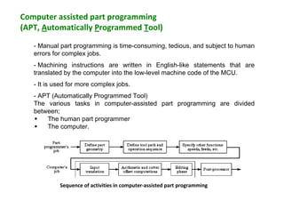
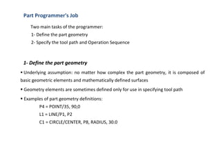
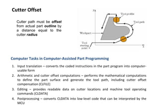
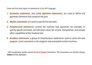
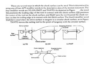
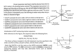
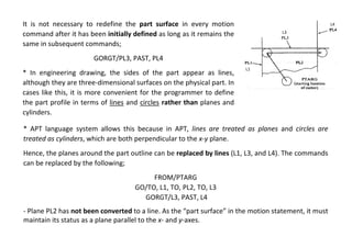
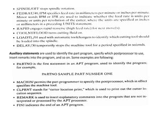
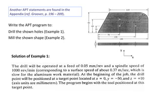
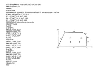
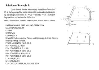
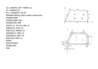
SlideShare a Scribd company logo
1 of 21
Download to read offline
Computer assisted part programming
(APT, Automatically Programmed Tool)
- Manual part programming is time-consuming, tedious, and subject to human
errors for complex jobs.
- Machining instructions are written in English-like statements that are
translated by the computer into the low-level machine code of the MCU.
- It is used for more complex jobs.
- APT (Automatically Programmed Tool)
The various tasks in computer-assisted part programming are divided
between;
 The human part programmer
 The computer.
Sequence of activities in computer-assisted part programming
Two main tasks of the programmer:
1- Define the part geometry
2- Specify the tool path and Operation Sequence
Part Programmer's Job
1- Define the part geometry
 Underlying assumption: no matter how complex the part geometry, it is composed of
basic geometric elements and mathematically defined surfaces
 Geometry elements are sometimes defined only for use in specifying tool path
 Examples of part geometry definitions:
P4 = POINT/35, 90,0
L1 = LINE/P1, P2
C1 = CIRCLE/CENTER, P8, RADIUS, 30.0
2- Specify the tool path and Operation Sequence
 Tool path consists of a sequence of points or connected line and arc segments, using
previously defined geometry elements
 Point-to-Point command:
GOTO/P0
 Continuous path command:
GOLFT/L2, TANTO, C1
Other Functions in Computer-Assisted Part Programming
• Specifying cutting speeds and feed rates
• Designating cutter size (for tool offset calculations)
• Specifying tolerances in circular interpolation
• Naming the program
• Identifying the machine tool
Cutter Offset
Cutter path must be offset
from actual part outline by
a distance equal to the
cutter radius
Computer Tasks in Computer-Assisted Part Programming
1. Input translation – converts the coded instructions in the part program into computer-
usable form
2. Arithmetic and cutter offset computations – performs the mathematical computations
to define the part surface and generate the tool path, including cutter offset
compensation (CLFILE)
3. Editing – provides readable data on cutter locations and machine tool operating
commands (CLDATA)
4. Postprocessing – converts CLDATA into low-level code that can be interpreted by the
MCU
There are four basic types of statements in the APT language:
1. Geometry statements, also called definition statements; are used to define the
geometry elements that comprise the part.
2. Motion commands; are used to specify the tool path.
3. Postprocessor statements; control the machine tool operation, for example, to
specify speeds and feeds, set tolerance values for circular interpolation, and actuate
other capabilities of the machine tool.
4. Auxiliary statements; a group of miscellaneous statements used to name the part
program, insert comments in the program and accomplish similar functions.
- APT vocabulary words consist of six or fewer characters. The characters are almost always
letters of the alphabet.
Geometry statements
The points, lines, and surfaces must be defined in the program prior to specifying the motion
statements. The general form of an APT geometry statement is the following:
SYMBOL = GEOMETRY TYPE/descriptive data
as an example;
P1 = POINT/20.0, 40.0, 60.0
A symbol can be nay combination of six or fewer alphabetical and numerical characters, at least
one of which must be alphabetical. Also the symbol cannot be an APT vocabulary word. Some
examples are presented in the following Table:
minor
words
major
words
Points
Points: Specification of a point can be accomplished by the following:
1) Designating its x-, y-, and z-coordinates;
P1 = POINT/15.0, 10.0, 25.0
2) As the intersection of two intersecting lines;
P2 = POINT/INTOF, L1, L2
L1 and L2 are two previously defined lines.
Lines
Lines: A line in APT is considered to be of infinite length in both directions. Specification of a line
can be accomplished by the following:
1) Two points through which it passes;
L1 = LINE/P3, P4
P3 and P4 are two previously defined points.
2) Passes through point (P5) and parallel to another line (L3) that has been previously defined;
L2 = LINE/P5, PARLEL, L3
Planes
Planes: In APT, a plane extends indefinitely. A plane can be defined by the following:
1) Three points through which it passes;
PL1 = PLANE/P1, P2, P3
P1, P2 and P3 must be non-collinear.
2) Passes through point (P2) and parallel to another plane (PL1) that has been previously
defined;
PL2 = PLANE/P2, PARLEL, PL1
Circles
Circles: In APT, a circle is considered to be a cylindrical surface that is perpendicular to the x-y
plane and extends to infinity in the z-direction. A circle can be defined by the following:
1) Its center and radius;
C1 = CIRCLE/CENTER, P1, RADIUS, 25.0
2) Three points through which it passes;
C2 = CIRCLE/P4, P5, P6
The three points must not be collinear.
Motion Commands
All APT motion statements follow a common format, just as geometry statements have their own
format. The general form of an APT motion command is:
MOTION COMMAND/descriptive data
as an example;
GOTO/P1
- At the beginning of the sequence of motion statements, the tool must be given a starting point.
This is likely to be the target point, the location where the operator has positioned the tool at the
start of the job. The part programmer keys into this starting position with the following statement:
FROM/PTARG
Where FROM is an APT vocabulary word indicating that this is the initial point from which all others
will be referenced; and PTARG is the symbol assigned to the starting point.
Another way to make this statement is the following:
FROM/-20.0, -20.0, 0
- The FROM statement occurs only at the start of the motion sequence.
It is appropriate to distinguish between point-to-point motions and contouring motions.
Point-to-point motions
There are two commands; GOTO and GODLTA.
* The GOTO statement instructs the tool to go to a particular point location specified in the
descriptive data. Two examples are:
GOTO/P2
GOTO/25.0, 40.0, 0
* The GODLTA command specifies an incremental move for the tool. To illustrate, the
following statement instruct the tool to move from its present position by a distance of 50
mm in x-direction, 120 mm in y-direction, and 40 mm in z-direction;
GODLTA/50.0, 120.0, 40.0
* The GODLTA statement is useful in drilling and related machining operations. The tool can
be directed to go to a given hole location; then the GODLTA command can be used to drill
the hole, as in the following sequence;
GOTO/P2
GODLTA/0, 0, -50.0
GODLTA/0, 0, 50.0
Contouring motions
These are more complicated than PTP commands are because the tool’s position must be
continuously controlled throughout the move.
• The tool is directed along two intersecting surfaces until it reaches a third surface, as shown
in the following Figure;
1. Drive surface; this is the surface that
guides the side of the cutter. It is
pictured as a plane in our Figure.
2. Part surface; this is the surface, again
pictured as a plane, on which the
bottom or nose of the tool is guided.
3. Check surface; this is the surface that
stops the forward motion of the tool
in the execution of the current
command. One might say that this
surface “checks” the advance of the
tool.
Initialization of APT contouring motion sequence:
With reference to the Figure, the sequence takes the following form:
FROM/PTARG
GO/TO, PL1, TO, PL2, TO, PL3
- The three surfaces included in the GO statement must be specified in the
order; (1) drive surface, (2) part surface, and (3) check surface.
- Note that GO/TO is not the same as the GOTO command. GOTO is used
only for PTP motions. The GO/ command is used to initialize a sequence of
contouring motions and may take alternative forms such as GO/ON,
GO/TO, or GO/PAST.
It is not necessary to redefine the part surface in every motion
command after it has been initially defined as long as it remains the
same in subsequent commands;
GORGT/PL3, PAST, PL4
* In engineering drawing, the sides of the part appear as lines,
although they are three-dimensional surfaces on the physical part. In
cases like this, it is more convenient for the programmer to define
the part profile in terms of lines and circles rather than planes and
cylinders.
* APT language system allows this because in APT, lines are treated as planes and circles are
treated as cylinders, which are both perpendicular to the x-y plane.
Hence, the planes around the part outline can be replaced by lines (L1, L3, and L4). The commands
can be replaced by the following;
FROM/PTARG
GO/TO, L1, TO, PL2, TO, L3
GORGT/L3, PAST, L4
- Plane PL2 has not been converted to a line. As the “part surface” in the motion statement, it must
maintain its status as a plane parallel to the x- and y-axes.
L1
L3
L4
Postprocessor and Auxiliary statements
Postprocessor statements control the operation of the machine tool and play a supporting role in
generating the tool path. Such statements are used to define cutter size, specify speeds and feeds,
turn coolant flow on and off, and control other features of the m/c tool. The general form of the
postprocessor statement is:
POSTPROCESSOR COMMAND/descriptive data
In some commands, the descriptive data is omitted. Some examples of the postprocessor
statements are the following:
Auxiliary statements are used to identify the part program, specify which postprocessor to use,
insert remarks into the program, and so on. Some examples are following:
x
y
Write the APT program to:
Drill the shown holes (Example 1).
Mill the shown shape (Example 2).
Solution of Example 1:
Another APT statements are found in the
Appendix (ref. Groover, p. 196 – 209).
PARTNO SAMPLE PART DRILLING OPERATION
MACHIN/DRILL,01
CLPRNT
UNITS/MM
REMARK Part geometry, Points are defined 10 mm above part surface.
PTARG = POINT/0, -50.0, 10.0
P5 = POINT/70.0, 30.0, 10.0
P6 = POINT/120.0, 30.0, 10.0
P7 = POINT/70.0, 60.0, 10.0
REMARK Drill bit motion statements.
FROM/PTARG
RAPID
GOTO/P5
SPINDL/1000, CLW
FEEDRAT/0.05, IPR
GODLTA/0, 0, -25.0
GODLTA/0, 0, 25.0
RAPID
GOTO/P6
SPINDL/1000, CLW
FEEDRAT/0.05, IPR
GODLTA/0, 0, -25.0
GODLTA/0, 0, 25.0
RAPID
GOTO/P7
SPINDL/1000, CLW
FEEDRAT/0.05, IPR
GODLTA/0, 0, -25.0
GODLTA/0, 0, 25.0
RAPID
GOTO/PTARG
SPINDL/OFF
FINI
Solution of Example 2:
Feed = 50 mm/min., Speed = 1000 rev/min., Cutter diam. = 20 mm.
PARTNO SAMPLE PART MILLING OPERATION
MACHIN/MILLING,02
CLPRNT
UNITS/MM
CUTTER/20.0
REMARK Part geometry, Points and Lines are defined 25 mm
below part top surface.
PTARG = POINT/0, -50.0, 10.0
P1 = POINT/0, 0, -25.0
P2 = POINT/160.0, 0, -25.0
P3 = POINT/160.0, 60.0, -25.0
P4 = POINT/35.0, 90.0, -25.0
P8 = POINT/130.0, 60.0, -25.0
L1 = LINE/P1, P2
L2 = LINE/P2, P3
C1 = CIRCLE/CENTER, P8, RADIUS, 30.0
L3 = LINE/P4, LEFT, TANTO, C1
L4 = LINE/P4, P1
PL1 = PLANE/P1, P2, P4
REMARK Milling cutter motion statements.
FROM/PTARG
SPINDL/1000, CLW
FEEDRAT/50, IPM
GO/TO, L1, TO, PL1, ON, L4
GORGT/L1, PAST, L2
GOLFT/L2, TANTO, C1
GOFWD/C1, PAST, L3
GOFWD/L3, PAST, L4
GOLFT/L4, PAST, L1
RAPID
GOTO/PTARG
SPINDL/OFF
FINI

More Related Content

What's hot

CNC part programming
CNC part programmingCNC part programming
CNC part programmingjntuhcej
 
DNC machines tools
DNC machines toolsDNC machines tools
DNC machines toolsjntuhcej
 
Manual part programming
Manual part programmingManual part programming
Manual part programmingjntuhcej
 
Cnc, dnc & adaptive control
Cnc, dnc & adaptive controlCnc, dnc & adaptive control
Cnc, dnc & adaptive controlparabajinkya0070
 
Unit 5-cad standards
Unit 5-cad standardsUnit 5-cad standards
Unit 5-cad standardsJavith Saleem
 
12 cnc & part programming
12 cnc & part programming12 cnc & part programming
12 cnc & part programmingM Siva Kumar
 
Group Technology, coding and cell design
Group Technology, coding and cell designGroup Technology, coding and cell design
Group Technology, coding and cell designNauman khan
 
COMPUTER AIDED PROCESS PLANNING
COMPUTER AIDED PROCESS PLANNINGCOMPUTER AIDED PROCESS PLANNING
COMPUTER AIDED PROCESS PLANNINGjntuhcej
 
Computer aided manufacturing
Computer aided manufacturingComputer aided manufacturing
Computer aided manufacturingGulfaraz alam
 
CNC principle & machining centre
CNC principle & machining centreCNC principle & machining centre
CNC principle & machining centreNirmalRaja3
 

What's hot (20)

NC, CNC & DNC Machine
NC, CNC & DNC Machine NC, CNC & DNC Machine
NC, CNC & DNC Machine
 
CNC part programming
CNC part programmingCNC part programming
CNC part programming
 
DNC machines tools
DNC machines toolsDNC machines tools
DNC machines tools
 
Theory of Metal Cutting
Theory of Metal CuttingTheory of Metal Cutting
Theory of Metal Cutting
 
DNC SYSTEMS
DNC SYSTEMSDNC SYSTEMS
DNC SYSTEMS
 
Numeric control
Numeric controlNumeric control
Numeric control
 
Manual part programming
Manual part programmingManual part programming
Manual part programming
 
Cnc, dnc & adaptive control
Cnc, dnc & adaptive controlCnc, dnc & adaptive control
Cnc, dnc & adaptive control
 
Unit 5-cad standards
Unit 5-cad standardsUnit 5-cad standards
Unit 5-cad standards
 
12 cnc & part programming
12 cnc & part programming12 cnc & part programming
12 cnc & part programming
 
Broaching machine
Broaching machineBroaching machine
Broaching machine
 
Group Technology, coding and cell design
Group Technology, coding and cell designGroup Technology, coding and cell design
Group Technology, coding and cell design
 
graphic stadards
graphic stadardsgraphic stadards
graphic stadards
 
COMPUTER AIDED PROCESS PLANNING
COMPUTER AIDED PROCESS PLANNINGCOMPUTER AIDED PROCESS PLANNING
COMPUTER AIDED PROCESS PLANNING
 
Computer aided manufacturing
Computer aided manufacturingComputer aided manufacturing
Computer aided manufacturing
 
Introduction to nc
Introduction to ncIntroduction to nc
Introduction to nc
 
CNC principle & machining centre
CNC principle & machining centreCNC principle & machining centre
CNC principle & machining centre
 
kinematic synthesis
kinematic synthesiskinematic synthesis
kinematic synthesis
 
Nc Machine
Nc MachineNc Machine
Nc Machine
 
Tool geometry
Tool geometryTool geometry
Tool geometry
 

Similar to Computer assisted part programming.pdf

NC part programing & Robotics
NC part programing & RoboticsNC part programing & Robotics
NC part programing & RoboticsDenny John
 
amit chauhan apt presentation
amit chauhan   apt presentationamit chauhan   apt presentation
amit chauhan apt presentationAkash Maurya
 
Industrial Automated Robots Working and explanation
Industrial Automated Robots Working and explanationIndustrial Automated Robots Working and explanation
Industrial Automated Robots Working and explanationSarmadFarooq5
 
06. industrial robotics
06. industrial robotics06. industrial robotics
06. industrial roboticsrichard visey
 
detail of flowchart and algorithm that are used in programmingpdf
detail of flowchart and algorithm that are used in programmingpdfdetail of flowchart and algorithm that are used in programmingpdf
detail of flowchart and algorithm that are used in programmingpdfssuserf86fba
 
Algorithm Flowchart Manual ALGORITHM FLOWCHART MANUAL For STUDENTS
Algorithm   Flowchart Manual ALGORITHM   FLOWCHART MANUAL For STUDENTSAlgorithm   Flowchart Manual ALGORITHM   FLOWCHART MANUAL For STUDENTS
Algorithm Flowchart Manual ALGORITHM FLOWCHART MANUAL For STUDENTSAlicia Edwards
 
4th sem,(cs is),computer org unit-7
4th sem,(cs is),computer org unit-74th sem,(cs is),computer org unit-7
4th sem,(cs is),computer org unit-7Sujay pai
 
APT part programming
APT part programmingAPT part programming
APT part programmingnmahi96
 
robot-pplication-200916054307.pptx
robot-pplication-200916054307.pptxrobot-pplication-200916054307.pptx
robot-pplication-200916054307.pptxDSelvamarilakshmiAss
 
7-CNC_Programming_For_Lathe_na_eng.pdf
7-CNC_Programming_For_Lathe_na_eng.pdf7-CNC_Programming_For_Lathe_na_eng.pdf
7-CNC_Programming_For_Lathe_na_eng.pdfssuser46f1ac
 
Robot programming , accuracy ,repeatability and application
Robot programming , accuracy ,repeatability  and applicationRobot programming , accuracy ,repeatability  and application
Robot programming , accuracy ,repeatability and applicationvishaldattKohir1
 
Mitsubishi ac servos melservo j4 series with built-in positioning function-di...
Mitsubishi ac servos melservo j4 series with built-in positioning function-di...Mitsubishi ac servos melservo j4 series with built-in positioning function-di...
Mitsubishi ac servos melservo j4 series with built-in positioning function-di...Dien Ha The
 

Similar to Computer assisted part programming.pdf (20)

NC part programing & Robotics
NC part programing & RoboticsNC part programing & Robotics
NC part programing & Robotics
 
amit chauhan apt presentation
amit chauhan   apt presentationamit chauhan   apt presentation
amit chauhan apt presentation
 
Industrial Automated Robots Working and explanation
Industrial Automated Robots Working and explanationIndustrial Automated Robots Working and explanation
Industrial Automated Robots Working and explanation
 
06. industrial robotics
06. industrial robotics06. industrial robotics
06. industrial robotics
 
Industrial robotics.pptx
Industrial robotics.pptxIndustrial robotics.pptx
Industrial robotics.pptx
 
detail of flowchart and algorithm that are used in programmingpdf
detail of flowchart and algorithm that are used in programmingpdfdetail of flowchart and algorithm that are used in programmingpdf
detail of flowchart and algorithm that are used in programmingpdf
 
Algorithm Flowchart Manual ALGORITHM FLOWCHART MANUAL For STUDENTS
Algorithm   Flowchart Manual ALGORITHM   FLOWCHART MANUAL For STUDENTSAlgorithm   Flowchart Manual ALGORITHM   FLOWCHART MANUAL For STUDENTS
Algorithm Flowchart Manual ALGORITHM FLOWCHART MANUAL For STUDENTS
 
Algorithm manual
Algorithm manualAlgorithm manual
Algorithm manual
 
4th sem,(cs is),computer org unit-7
4th sem,(cs is),computer org unit-74th sem,(cs is),computer org unit-7
4th sem,(cs is),computer org unit-7
 
Modul PLC Programming.pdf
Modul PLC Programming.pdfModul PLC Programming.pdf
Modul PLC Programming.pdf
 
APT part programming
APT part programmingAPT part programming
APT part programming
 
robot-pplication-200916054307.pptx
robot-pplication-200916054307.pptxrobot-pplication-200916054307.pptx
robot-pplication-200916054307.pptx
 
Loader
LoaderLoader
Loader
 
Assembler
AssemblerAssembler
Assembler
 
Assembler
AssemblerAssembler
Assembler
 
bus system.pptx
bus system.pptxbus system.pptx
bus system.pptx
 
7-CNC_Programming_For_Lathe_na_eng.pdf
7-CNC_Programming_For_Lathe_na_eng.pdf7-CNC_Programming_For_Lathe_na_eng.pdf
7-CNC_Programming_For_Lathe_na_eng.pdf
 
Robot programming , accuracy ,repeatability and application
Robot programming , accuracy ,repeatability  and applicationRobot programming , accuracy ,repeatability  and application
Robot programming , accuracy ,repeatability and application
 
Assembler
AssemblerAssembler
Assembler
 
Mitsubishi ac servos melservo j4 series with built-in positioning function-di...
Mitsubishi ac servos melservo j4 series with built-in positioning function-di...Mitsubishi ac servos melservo j4 series with built-in positioning function-di...
Mitsubishi ac servos melservo j4 series with built-in positioning function-di...
 

More from Ashok Mannava

Sole_Proprietorship_Presentation.pptx
Sole_Proprietorship_Presentation.pptxSole_Proprietorship_Presentation.pptx
Sole_Proprietorship_Presentation.pptxAshok Mannava
 
notes_9 Lec PP and CAPP.pptx
notes_9 Lec PP and CAPP.pptxnotes_9 Lec PP and CAPP.pptx
notes_9 Lec PP and CAPP.pptxAshok Mannava
 
Cell_Manufacturing.ppt
Cell_Manufacturing.pptCell_Manufacturing.ppt
Cell_Manufacturing.pptAshok Mannava
 
Group Technology Basics.ppt
Group Technology Basics.pptGroup Technology Basics.ppt
Group Technology Basics.pptAshok Mannava
 
443439858 the-mesopotamian-civiliation-ppt
443439858 the-mesopotamian-civiliation-ppt443439858 the-mesopotamian-civiliation-ppt
443439858 the-mesopotamian-civiliation-pptAshok Mannava
 
Uvl simplysupported beam
Uvl simplysupported beamUvl simplysupported beam
Uvl simplysupported beamAshok Mannava
 
Agriculture chapter 10
Agriculture chapter 10Agriculture chapter 10
Agriculture chapter 10Ashok Mannava
 
Agricultural revolution
Agricultural revolutionAgricultural revolution
Agricultural revolutionAshok Mannava
 
77102350 7-8-cutting-tool-materials-complete-ppt
77102350 7-8-cutting-tool-materials-complete-ppt77102350 7-8-cutting-tool-materials-complete-ppt
77102350 7-8-cutting-tool-materials-complete-pptAshok Mannava
 
168 w1a0352 intern ppt
168 w1a0352 intern ppt168 w1a0352 intern ppt
168 w1a0352 intern pptAshok Mannava
 

More from Ashok Mannava (20)

Sole_Proprietorship_Presentation.pptx
Sole_Proprietorship_Presentation.pptxSole_Proprietorship_Presentation.pptx
Sole_Proprietorship_Presentation.pptx
 
Model QP (1).docx
Model QP (1).docxModel QP (1).docx
Model QP (1).docx
 
notes_9 Lec PP and CAPP.pptx
notes_9 Lec PP and CAPP.pptxnotes_9 Lec PP and CAPP.pptx
notes_9 Lec PP and CAPP.pptx
 
Cell_Manufacturing.ppt
Cell_Manufacturing.pptCell_Manufacturing.ppt
Cell_Manufacturing.ppt
 
Group Technology Basics.ppt
Group Technology Basics.pptGroup Technology Basics.ppt
Group Technology Basics.ppt
 
Ie550nc
Ie550ncIe550nc
Ie550nc
 
443439858 the-mesopotamian-civiliation-ppt
443439858 the-mesopotamian-civiliation-ppt443439858 the-mesopotamian-civiliation-ppt
443439858 the-mesopotamian-civiliation-ppt
 
Uvl simplysupported beam
Uvl simplysupported beamUvl simplysupported beam
Uvl simplysupported beam
 
What is technology
What is technologyWhat is technology
What is technology
 
Transducer
TransducerTransducer
Transducer
 
Cmm
CmmCmm
Cmm
 
Capacitance
CapacitanceCapacitance
Capacitance
 
Auto cad material
Auto cad materialAuto cad material
Auto cad material
 
L5 2018 09_17
L5 2018 09_17L5 2018 09_17
L5 2018 09_17
 
Agriculture chapter 10
Agriculture chapter 10Agriculture chapter 10
Agriculture chapter 10
 
Agricultural revolution
Agricultural revolutionAgricultural revolution
Agricultural revolution
 
77102350 7-8-cutting-tool-materials-complete-ppt
77102350 7-8-cutting-tool-materials-complete-ppt77102350 7-8-cutting-tool-materials-complete-ppt
77102350 7-8-cutting-tool-materials-complete-ppt
 
Compressor final
Compressor finalCompressor final
Compressor final
 
Dht
DhtDht
Dht
 
168 w1a0352 intern ppt
168 w1a0352 intern ppt168 w1a0352 intern ppt
168 w1a0352 intern ppt
 

Recently uploaded

Booking open Available Pune Call Girls Koregaon Park 6297143586 Call Hot Ind...
Booking open Available Pune Call Girls Koregaon Park  6297143586 Call Hot Ind...Booking open Available Pune Call Girls Koregaon Park  6297143586 Call Hot Ind...
Booking open Available Pune Call Girls Koregaon Park 6297143586 Call Hot Ind...Call Girls in Nagpur High Profile
 
(ANVI) Koregaon Park Call Girls Just Call 7001035870 [ Cash on Delivery ] Pun...
(ANVI) Koregaon Park Call Girls Just Call 7001035870 [ Cash on Delivery ] Pun...(ANVI) Koregaon Park Call Girls Just Call 7001035870 [ Cash on Delivery ] Pun...
(ANVI) Koregaon Park Call Girls Just Call 7001035870 [ Cash on Delivery ] Pun...ranjana rawat
 
CCS335 _ Neural Networks and Deep Learning Laboratory_Lab Complete Record
CCS335 _ Neural Networks and Deep Learning Laboratory_Lab Complete RecordCCS335 _ Neural Networks and Deep Learning Laboratory_Lab Complete Record
CCS335 _ Neural Networks and Deep Learning Laboratory_Lab Complete RecordAsst.prof M.Gokilavani
 
Call Girls Service Nashik Vaishnavi 7001305949 Independent Escort Service Nashik
Call Girls Service Nashik Vaishnavi 7001305949 Independent Escort Service NashikCall Girls Service Nashik Vaishnavi 7001305949 Independent Escort Service Nashik
Call Girls Service Nashik Vaishnavi 7001305949 Independent Escort Service NashikCall Girls in Nagpur High Profile
 
KubeKraft presentation @CloudNativeHooghly
KubeKraft presentation @CloudNativeHooghlyKubeKraft presentation @CloudNativeHooghly
KubeKraft presentation @CloudNativeHooghlysanyuktamishra911
 
VIP Call Girls Service Hitech City Hyderabad Call +91-8250192130
VIP Call Girls Service Hitech City Hyderabad Call +91-8250192130VIP Call Girls Service Hitech City Hyderabad Call +91-8250192130
VIP Call Girls Service Hitech City Hyderabad Call +91-8250192130Suhani Kapoor
 
247267395-1-Symmetric-and-distributed-shared-memory-architectures-ppt (1).ppt
247267395-1-Symmetric-and-distributed-shared-memory-architectures-ppt (1).ppt247267395-1-Symmetric-and-distributed-shared-memory-architectures-ppt (1).ppt
247267395-1-Symmetric-and-distributed-shared-memory-architectures-ppt (1).pptssuser5c9d4b1
 
Coefficient of Thermal Expansion and their Importance.pptx
Coefficient of Thermal Expansion and their Importance.pptxCoefficient of Thermal Expansion and their Importance.pptx
Coefficient of Thermal Expansion and their Importance.pptxAsutosh Ranjan
 
(ANJALI) Dange Chowk Call Girls Just Call 7001035870 [ Cash on Delivery ] Pun...
(ANJALI) Dange Chowk Call Girls Just Call 7001035870 [ Cash on Delivery ] Pun...(ANJALI) Dange Chowk Call Girls Just Call 7001035870 [ Cash on Delivery ] Pun...
(ANJALI) Dange Chowk Call Girls Just Call 7001035870 [ Cash on Delivery ] Pun...ranjana rawat
 
The Most Attractive Pune Call Girls Budhwar Peth 8250192130 Will You Miss Thi...
The Most Attractive Pune Call Girls Budhwar Peth 8250192130 Will You Miss Thi...The Most Attractive Pune Call Girls Budhwar Peth 8250192130 Will You Miss Thi...
The Most Attractive Pune Call Girls Budhwar Peth 8250192130 Will You Miss Thi...ranjana rawat
 
Introduction to Multiple Access Protocol.pptx
Introduction to Multiple Access Protocol.pptxIntroduction to Multiple Access Protocol.pptx
Introduction to Multiple Access Protocol.pptxupamatechverse
 
APPLICATIONS-AC/DC DRIVES-OPERATING CHARACTERISTICS
APPLICATIONS-AC/DC DRIVES-OPERATING CHARACTERISTICSAPPLICATIONS-AC/DC DRIVES-OPERATING CHARACTERISTICS
APPLICATIONS-AC/DC DRIVES-OPERATING CHARACTERISTICSKurinjimalarL3
 
UNIT-II FMM-Flow Through Circular Conduits
UNIT-II FMM-Flow Through Circular ConduitsUNIT-II FMM-Flow Through Circular Conduits
UNIT-II FMM-Flow Through Circular Conduitsrknatarajan
 
HARDNESS, FRACTURE TOUGHNESS AND STRENGTH OF CERAMICS
HARDNESS, FRACTURE TOUGHNESS AND STRENGTH OF CERAMICSHARDNESS, FRACTURE TOUGHNESS AND STRENGTH OF CERAMICS
HARDNESS, FRACTURE TOUGHNESS AND STRENGTH OF CERAMICSRajkumarAkumalla
 
Porous Ceramics seminar and technical writing
Porous Ceramics seminar and technical writingPorous Ceramics seminar and technical writing
Porous Ceramics seminar and technical writingrakeshbaidya232001
 
AKTU Computer Networks notes --- Unit 3.pdf
AKTU Computer Networks notes ---  Unit 3.pdfAKTU Computer Networks notes ---  Unit 3.pdf
AKTU Computer Networks notes --- Unit 3.pdfankushspencer015
 
Java Programming :Event Handling(Types of Events)
Java Programming :Event Handling(Types of Events)Java Programming :Event Handling(Types of Events)
Java Programming :Event Handling(Types of Events)simmis5
 
Sheet Pile Wall Design and Construction: A Practical Guide for Civil Engineer...
Sheet Pile Wall Design and Construction: A Practical Guide for Civil Engineer...Sheet Pile Wall Design and Construction: A Practical Guide for Civil Engineer...
Sheet Pile Wall Design and Construction: A Practical Guide for Civil Engineer...Dr.Costas Sachpazis
 
Introduction to IEEE STANDARDS and its different types.pptx
Introduction to IEEE STANDARDS and its different types.pptxIntroduction to IEEE STANDARDS and its different types.pptx
Introduction to IEEE STANDARDS and its different types.pptxupamatechverse
 

Recently uploaded (20)

Booking open Available Pune Call Girls Koregaon Park 6297143586 Call Hot Ind...
Booking open Available Pune Call Girls Koregaon Park  6297143586 Call Hot Ind...Booking open Available Pune Call Girls Koregaon Park  6297143586 Call Hot Ind...
Booking open Available Pune Call Girls Koregaon Park 6297143586 Call Hot Ind...
 
(ANVI) Koregaon Park Call Girls Just Call 7001035870 [ Cash on Delivery ] Pun...
(ANVI) Koregaon Park Call Girls Just Call 7001035870 [ Cash on Delivery ] Pun...(ANVI) Koregaon Park Call Girls Just Call 7001035870 [ Cash on Delivery ] Pun...
(ANVI) Koregaon Park Call Girls Just Call 7001035870 [ Cash on Delivery ] Pun...
 
CCS335 _ Neural Networks and Deep Learning Laboratory_Lab Complete Record
CCS335 _ Neural Networks and Deep Learning Laboratory_Lab Complete RecordCCS335 _ Neural Networks and Deep Learning Laboratory_Lab Complete Record
CCS335 _ Neural Networks and Deep Learning Laboratory_Lab Complete Record
 
Call Girls Service Nashik Vaishnavi 7001305949 Independent Escort Service Nashik
Call Girls Service Nashik Vaishnavi 7001305949 Independent Escort Service NashikCall Girls Service Nashik Vaishnavi 7001305949 Independent Escort Service Nashik
Call Girls Service Nashik Vaishnavi 7001305949 Independent Escort Service Nashik
 
KubeKraft presentation @CloudNativeHooghly
KubeKraft presentation @CloudNativeHooghlyKubeKraft presentation @CloudNativeHooghly
KubeKraft presentation @CloudNativeHooghly
 
VIP Call Girls Service Hitech City Hyderabad Call +91-8250192130
VIP Call Girls Service Hitech City Hyderabad Call +91-8250192130VIP Call Girls Service Hitech City Hyderabad Call +91-8250192130
VIP Call Girls Service Hitech City Hyderabad Call +91-8250192130
 
247267395-1-Symmetric-and-distributed-shared-memory-architectures-ppt (1).ppt
247267395-1-Symmetric-and-distributed-shared-memory-architectures-ppt (1).ppt247267395-1-Symmetric-and-distributed-shared-memory-architectures-ppt (1).ppt
247267395-1-Symmetric-and-distributed-shared-memory-architectures-ppt (1).ppt
 
Coefficient of Thermal Expansion and their Importance.pptx
Coefficient of Thermal Expansion and their Importance.pptxCoefficient of Thermal Expansion and their Importance.pptx
Coefficient of Thermal Expansion and their Importance.pptx
 
(ANJALI) Dange Chowk Call Girls Just Call 7001035870 [ Cash on Delivery ] Pun...
(ANJALI) Dange Chowk Call Girls Just Call 7001035870 [ Cash on Delivery ] Pun...(ANJALI) Dange Chowk Call Girls Just Call 7001035870 [ Cash on Delivery ] Pun...
(ANJALI) Dange Chowk Call Girls Just Call 7001035870 [ Cash on Delivery ] Pun...
 
The Most Attractive Pune Call Girls Budhwar Peth 8250192130 Will You Miss Thi...
The Most Attractive Pune Call Girls Budhwar Peth 8250192130 Will You Miss Thi...The Most Attractive Pune Call Girls Budhwar Peth 8250192130 Will You Miss Thi...
The Most Attractive Pune Call Girls Budhwar Peth 8250192130 Will You Miss Thi...
 
Introduction to Multiple Access Protocol.pptx
Introduction to Multiple Access Protocol.pptxIntroduction to Multiple Access Protocol.pptx
Introduction to Multiple Access Protocol.pptx
 
APPLICATIONS-AC/DC DRIVES-OPERATING CHARACTERISTICS
APPLICATIONS-AC/DC DRIVES-OPERATING CHARACTERISTICSAPPLICATIONS-AC/DC DRIVES-OPERATING CHARACTERISTICS
APPLICATIONS-AC/DC DRIVES-OPERATING CHARACTERISTICS
 
UNIT-II FMM-Flow Through Circular Conduits
UNIT-II FMM-Flow Through Circular ConduitsUNIT-II FMM-Flow Through Circular Conduits
UNIT-II FMM-Flow Through Circular Conduits
 
HARDNESS, FRACTURE TOUGHNESS AND STRENGTH OF CERAMICS
HARDNESS, FRACTURE TOUGHNESS AND STRENGTH OF CERAMICSHARDNESS, FRACTURE TOUGHNESS AND STRENGTH OF CERAMICS
HARDNESS, FRACTURE TOUGHNESS AND STRENGTH OF CERAMICS
 
Porous Ceramics seminar and technical writing
Porous Ceramics seminar and technical writingPorous Ceramics seminar and technical writing
Porous Ceramics seminar and technical writing
 
Roadmap to Membership of RICS - Pathways and Routes
Roadmap to Membership of RICS - Pathways and RoutesRoadmap to Membership of RICS - Pathways and Routes
Roadmap to Membership of RICS - Pathways and Routes
 
AKTU Computer Networks notes --- Unit 3.pdf
AKTU Computer Networks notes ---  Unit 3.pdfAKTU Computer Networks notes ---  Unit 3.pdf
AKTU Computer Networks notes --- Unit 3.pdf
 
Java Programming :Event Handling(Types of Events)
Java Programming :Event Handling(Types of Events)Java Programming :Event Handling(Types of Events)
Java Programming :Event Handling(Types of Events)
 
Sheet Pile Wall Design and Construction: A Practical Guide for Civil Engineer...
Sheet Pile Wall Design and Construction: A Practical Guide for Civil Engineer...Sheet Pile Wall Design and Construction: A Practical Guide for Civil Engineer...
Sheet Pile Wall Design and Construction: A Practical Guide for Civil Engineer...
 
Introduction to IEEE STANDARDS and its different types.pptx
Introduction to IEEE STANDARDS and its different types.pptxIntroduction to IEEE STANDARDS and its different types.pptx
Introduction to IEEE STANDARDS and its different types.pptx
 

Computer assisted part programming.pdf

  • 1. Computer assisted part programming (APT, Automatically Programmed Tool) - Manual part programming is time-consuming, tedious, and subject to human errors for complex jobs. - Machining instructions are written in English-like statements that are translated by the computer into the low-level machine code of the MCU. - It is used for more complex jobs. - APT (Automatically Programmed Tool) The various tasks in computer-assisted part programming are divided between; The human part programmer The computer. Sequence of activities in computer-assisted part programming
  • 2. Two main tasks of the programmer: 1- Define the part geometry 2- Specify the tool path and Operation Sequence Part Programmer's Job 1- Define the part geometry Underlying assumption: no matter how complex the part geometry, it is composed of basic geometric elements and mathematically defined surfaces Geometry elements are sometimes defined only for use in specifying tool path Examples of part geometry definitions: P4 = POINT/35, 90,0 L1 = LINE/P1, P2 C1 = CIRCLE/CENTER, P8, RADIUS, 30.0
  • 3. 2- Specify the tool path and Operation Sequence Tool path consists of a sequence of points or connected line and arc segments, using previously defined geometry elements Point-to-Point command: GOTO/P0 Continuous path command: GOLFT/L2, TANTO, C1 Other Functions in Computer-Assisted Part Programming • Specifying cutting speeds and feed rates • Designating cutter size (for tool offset calculations) • Specifying tolerances in circular interpolation • Naming the program • Identifying the machine tool
  • 4. Cutter Offset Cutter path must be offset from actual part outline by a distance equal to the cutter radius Computer Tasks in Computer-Assisted Part Programming 1. Input translation – converts the coded instructions in the part program into computer- usable form 2. Arithmetic and cutter offset computations – performs the mathematical computations to define the part surface and generate the tool path, including cutter offset compensation (CLFILE) 3. Editing – provides readable data on cutter locations and machine tool operating commands (CLDATA) 4. Postprocessing – converts CLDATA into low-level code that can be interpreted by the MCU
  • 5. There are four basic types of statements in the APT language: 1. Geometry statements, also called definition statements; are used to define the geometry elements that comprise the part. 2. Motion commands; are used to specify the tool path. 3. Postprocessor statements; control the machine tool operation, for example, to specify speeds and feeds, set tolerance values for circular interpolation, and actuate other capabilities of the machine tool. 4. Auxiliary statements; a group of miscellaneous statements used to name the part program, insert comments in the program and accomplish similar functions. - APT vocabulary words consist of six or fewer characters. The characters are almost always letters of the alphabet.
  • 6. Geometry statements The points, lines, and surfaces must be defined in the program prior to specifying the motion statements. The general form of an APT geometry statement is the following: SYMBOL = GEOMETRY TYPE/descriptive data as an example; P1 = POINT/20.0, 40.0, 60.0 A symbol can be nay combination of six or fewer alphabetical and numerical characters, at least one of which must be alphabetical. Also the symbol cannot be an APT vocabulary word. Some examples are presented in the following Table: minor words major words
  • 7. Points Points: Specification of a point can be accomplished by the following: 1) Designating its x-, y-, and z-coordinates; P1 = POINT/15.0, 10.0, 25.0 2) As the intersection of two intersecting lines; P2 = POINT/INTOF, L1, L2 L1 and L2 are two previously defined lines. Lines Lines: A line in APT is considered to be of infinite length in both directions. Specification of a line can be accomplished by the following: 1) Two points through which it passes; L1 = LINE/P3, P4 P3 and P4 are two previously defined points. 2) Passes through point (P5) and parallel to another line (L3) that has been previously defined; L2 = LINE/P5, PARLEL, L3
  • 8. Planes Planes: In APT, a plane extends indefinitely. A plane can be defined by the following: 1) Three points through which it passes; PL1 = PLANE/P1, P2, P3 P1, P2 and P3 must be non-collinear. 2) Passes through point (P2) and parallel to another plane (PL1) that has been previously defined; PL2 = PLANE/P2, PARLEL, PL1 Circles Circles: In APT, a circle is considered to be a cylindrical surface that is perpendicular to the x-y plane and extends to infinity in the z-direction. A circle can be defined by the following: 1) Its center and radius; C1 = CIRCLE/CENTER, P1, RADIUS, 25.0 2) Three points through which it passes; C2 = CIRCLE/P4, P5, P6 The three points must not be collinear.
  • 9.
  • 10. Motion Commands All APT motion statements follow a common format, just as geometry statements have their own format. The general form of an APT motion command is: MOTION COMMAND/descriptive data as an example; GOTO/P1 - At the beginning of the sequence of motion statements, the tool must be given a starting point. This is likely to be the target point, the location where the operator has positioned the tool at the start of the job. The part programmer keys into this starting position with the following statement: FROM/PTARG Where FROM is an APT vocabulary word indicating that this is the initial point from which all others will be referenced; and PTARG is the symbol assigned to the starting point. Another way to make this statement is the following: FROM/-20.0, -20.0, 0 - The FROM statement occurs only at the start of the motion sequence.
  • 11. It is appropriate to distinguish between point-to-point motions and contouring motions. Point-to-point motions There are two commands; GOTO and GODLTA. * The GOTO statement instructs the tool to go to a particular point location specified in the descriptive data. Two examples are: GOTO/P2 GOTO/25.0, 40.0, 0 * The GODLTA command specifies an incremental move for the tool. To illustrate, the following statement instruct the tool to move from its present position by a distance of 50 mm in x-direction, 120 mm in y-direction, and 40 mm in z-direction; GODLTA/50.0, 120.0, 40.0 * The GODLTA statement is useful in drilling and related machining operations. The tool can be directed to go to a given hole location; then the GODLTA command can be used to drill the hole, as in the following sequence; GOTO/P2 GODLTA/0, 0, -50.0 GODLTA/0, 0, 50.0
  • 12. Contouring motions These are more complicated than PTP commands are because the tool’s position must be continuously controlled throughout the move. • The tool is directed along two intersecting surfaces until it reaches a third surface, as shown in the following Figure; 1. Drive surface; this is the surface that guides the side of the cutter. It is pictured as a plane in our Figure. 2. Part surface; this is the surface, again pictured as a plane, on which the bottom or nose of the tool is guided. 3. Check surface; this is the surface that stops the forward motion of the tool in the execution of the current command. One might say that this surface “checks” the advance of the tool.
  • 13.
  • 14. Initialization of APT contouring motion sequence: With reference to the Figure, the sequence takes the following form: FROM/PTARG GO/TO, PL1, TO, PL2, TO, PL3 - The three surfaces included in the GO statement must be specified in the order; (1) drive surface, (2) part surface, and (3) check surface. - Note that GO/TO is not the same as the GOTO command. GOTO is used only for PTP motions. The GO/ command is used to initialize a sequence of contouring motions and may take alternative forms such as GO/ON, GO/TO, or GO/PAST.
  • 15. It is not necessary to redefine the part surface in every motion command after it has been initially defined as long as it remains the same in subsequent commands; GORGT/PL3, PAST, PL4 * In engineering drawing, the sides of the part appear as lines, although they are three-dimensional surfaces on the physical part. In cases like this, it is more convenient for the programmer to define the part profile in terms of lines and circles rather than planes and cylinders. * APT language system allows this because in APT, lines are treated as planes and circles are treated as cylinders, which are both perpendicular to the x-y plane. Hence, the planes around the part outline can be replaced by lines (L1, L3, and L4). The commands can be replaced by the following; FROM/PTARG GO/TO, L1, TO, PL2, TO, L3 GORGT/L3, PAST, L4 - Plane PL2 has not been converted to a line. As the “part surface” in the motion statement, it must maintain its status as a plane parallel to the x- and y-axes. L1 L3 L4
  • 16. Postprocessor and Auxiliary statements Postprocessor statements control the operation of the machine tool and play a supporting role in generating the tool path. Such statements are used to define cutter size, specify speeds and feeds, turn coolant flow on and off, and control other features of the m/c tool. The general form of the postprocessor statement is: POSTPROCESSOR COMMAND/descriptive data In some commands, the descriptive data is omitted. Some examples of the postprocessor statements are the following:
  • 17. Auxiliary statements are used to identify the part program, specify which postprocessor to use, insert remarks into the program, and so on. Some examples are following:
  • 18. x y Write the APT program to: Drill the shown holes (Example 1). Mill the shown shape (Example 2). Solution of Example 1: Another APT statements are found in the Appendix (ref. Groover, p. 196 – 209).
  • 19. PARTNO SAMPLE PART DRILLING OPERATION MACHIN/DRILL,01 CLPRNT UNITS/MM REMARK Part geometry, Points are defined 10 mm above part surface. PTARG = POINT/0, -50.0, 10.0 P5 = POINT/70.0, 30.0, 10.0 P6 = POINT/120.0, 30.0, 10.0 P7 = POINT/70.0, 60.0, 10.0 REMARK Drill bit motion statements. FROM/PTARG RAPID GOTO/P5 SPINDL/1000, CLW FEEDRAT/0.05, IPR GODLTA/0, 0, -25.0 GODLTA/0, 0, 25.0 RAPID GOTO/P6 SPINDL/1000, CLW FEEDRAT/0.05, IPR GODLTA/0, 0, -25.0 GODLTA/0, 0, 25.0 RAPID GOTO/P7 SPINDL/1000, CLW FEEDRAT/0.05, IPR GODLTA/0, 0, -25.0 GODLTA/0, 0, 25.0 RAPID GOTO/PTARG SPINDL/OFF FINI
  • 20. Solution of Example 2: Feed = 50 mm/min., Speed = 1000 rev/min., Cutter diam. = 20 mm. PARTNO SAMPLE PART MILLING OPERATION MACHIN/MILLING,02 CLPRNT UNITS/MM CUTTER/20.0 REMARK Part geometry, Points and Lines are defined 25 mm below part top surface. PTARG = POINT/0, -50.0, 10.0 P1 = POINT/0, 0, -25.0 P2 = POINT/160.0, 0, -25.0 P3 = POINT/160.0, 60.0, -25.0 P4 = POINT/35.0, 90.0, -25.0 P8 = POINT/130.0, 60.0, -25.0 L1 = LINE/P1, P2 L2 = LINE/P2, P3 C1 = CIRCLE/CENTER, P8, RADIUS, 30.0
  • 21. L3 = LINE/P4, LEFT, TANTO, C1 L4 = LINE/P4, P1 PL1 = PLANE/P1, P2, P4 REMARK Milling cutter motion statements. FROM/PTARG SPINDL/1000, CLW FEEDRAT/50, IPM GO/TO, L1, TO, PL1, ON, L4 GORGT/L1, PAST, L2 GOLFT/L2, TANTO, C1 GOFWD/C1, PAST, L3 GOFWD/L3, PAST, L4 GOLFT/L4, PAST, L1 RAPID GOTO/PTARG SPINDL/OFF FINI