SlideShare a Scribd company logo
1 of 60
N01 G91 G71 M03 S800 (incremental mode, metric, spindle start with a speed of 800 rpm)
N02 G00 X1.0 (tool away from work piece 1mm, rapid)
N03 G00 Z-1.0 (tool to left 1mm for facing)
N04 G01 X-16.0 F200 (facing cut at a feed rate 200mm/min)
N05 G00 Z1.0 (move tool to right 1mm from that position)
N06 G00 X10.0 (move 10 mm away from the centre in x direction)
N07G01 Z-36.0 (plane turning over a length of 35 mm)
N08 G01 X5.0 Z-30.0 (simultaneous movement in X and Z directions for taper turning)
N09 G00 X1.0 Z66.0 (move to the starting position)
N10 M02 (end of program)
G/M Code program for Turning
APT (Automatically Programmed Tool)
Part will be defined in the Cartesian
coordinate system as shown in fig.1.
y
z
x
11/19/2021
Part Programming
APT (Automatically Programmed Tool) is a
software compiler for simplifying numerical
control Programming.
Developed by MIT in 1959
APT is the most widely used processor
11/19/2021
APT
APT (Automatically Programmed Tool) is a
software compiler for simplifying numerical
control Programming.
Developed by MIT in 1959
APT is the most widely used processor
11/19/2021
APT Characteristics
•
Three-dimensional unbounded surfaces and points are
defined to represent the part to be made
•
Surfaces are defined in a X-Y-Z coordinate system
•
In Programming, the tool does all the moving; the part is
stationary.
•
Linear interpolation is used for curved tool paths
11/19/2021
APT Statement Types (5)
•
Identification
•
Geometry
•
Motion
•
Postprocessor (feed, speed, coolant, …
etc.)
•
Auxiliary (tool, tolerance, part, … etc.)
The general format for geometric statements is:
<Symbol> = Geometric Type/ Definitional
Modifiers
Point (POINT)
PTA
PTA = POINT/ 3,4,5
y
x
z
(3, 4, 5)
Point (POINT)
PTB = POINT/ INTOF, LIN1, LIN2
LIN2
LIN1
PTB
Point (POINT)
PTD = POINT/ YSMALL, INTOF, LIN3, C1
PTD = POINT/ XSMALL, INTOF, LIN3, C1
x
PTC
PTD
LIN3
C1
y
PTC = POINT/ YLARGE, INTOF, LIN3, C1
PTC = POINT/ XLARGE, INTOF, LIN3, C1
Point (POINT)
PTE = POINT/ YLARGE, INTOF, C1, C2
PTE = POINT/ XLARGE, INTOF, C1, C2
y
x
C1
C2
PTE
PTF
PTF = POINT/ YSMALL, INTOF, C1, C2
PTF = POINT/ XSMALL, INTOF, C1, C2
Point (POINT)
PT7 = POINT/ CENTER, C6
C6
PT7
y
x
Point (POINT)
PT11 = POINT/ P63, RADIUS, 7.3, ATANGLE, 27
27°
P63 = 3.1, 6.7
PT11
y
x
7.3
Line (LINE)
LIN1 = LINE/ P1, P2
LIN1
P1
P2
y
x
Line (LINE)
LIN4 = LINE/ PT6, 15, -30, 3
PT6
L4 (15, -30, 3)
y
x
Line (LINE)
LIN10 = LINE/ 20, 3.5, 0.2, 31, 6.2, 1.3
(20, 3.5, 0.2)
L10
(31, 6.2, 1.3)
y
x
Line (LINE)
L12 = LINE/ PT4, ATANGL, 20, XAXIS
L14 = LINE/ PT1, ATANGL, 40
L15 = LINE/ 32, -3, 2, ATANGL, -15, XAXIS
L16 = LINE/ PT3, ATANGL, 40, YAXIS
y
x
L16
PT3
PT1
L14
L12
PT4
(32, -3, 2)
L15
40°
40° 20°
15°
Line (LINE)
LIN = LINE/ POINT, ATANGL, ANGLE (in degrees), LINE
P1
LINE1
LINE2
x
y
LINE2 = LINE/ P1, ATANGL, 30, LINE1
30°
Line (LINE)
LIN = LINE/ SLOPE, SLOPE VALUE, INTERC, MODIFIER, d
where the slope value is y/x. The modifier options are [XAXIS,
YAXIS], and d is the corresponding intercept value on the selected
axis (i.e., modifier).
x
y
(6,0) Point of X-Intercept
LINE1
LINE1 = LINE/ SLOPE, 1, INTERC, XAXIS, 6
Line (LINE)
LIN = LINE/ ATANGL, DEGREES, INTERC, MODIFIER, d
The modifier options are [XAXIS, YAXIS], and d is the
corresponding intercept value on the selected axis (i.e., modifier).
x
y
d
LINE1
 = 30°
LINE1 = LINE/ ATANGL, 30, INTERC, XAXIS ,d
Line (LINE)
The LEFT & RIGHT modifier indicates whether the line
is at the left or right tangent point, depending on how
one looks at the circle from the point.
L1 = LINE/ PT51, LEFT, TANTO, C11
L1
C11
PT51
Line (LINE)
L2 = LINE/ PT51, RIGHT, TANTO, C11
L1 = LINE/ PT40, RIGHT, TANTO, C11
L4 = LINE/ PT40, LEFT, TANTO, C11
Left
Right
PT51
L1
L3
L4
L2
Right
Left
PT40
Line (LINE)
L6 = LINE/ LEFT, TANTO, C3, LEFT, TANTO, C4
C3
L6
L9
C4
L8
L7
Right
Left
Left
Right
Line (LINE)
L7 = LINE/ LEFT, TANTO, C3, RIGHT, TANTO, C4
L7 = LINE/ LEFT, TANTO, C4, RIGHT, TANTO, C3
C3
L6
L
9
C4
L8
L7
Right
Left
Lef
t
Right
Line (LINE)
L8 = LINE/ RIGHT, TANTO, C3, LEFT, TANTO, C4
C3
L6
L9
C4
L8
L7
Right
Left
Left
Right
Line (LINE)
L9 = LINE/ RIGHT, TANTO, C3, RIGHT, TANTO, C4
L9 = LINE/ LEFT, TANTO, C4, LEFT, TANTO, C3
C3
L6
L9
C4
L8
L7
Right
Left
Left
Right
Line (LINE)
LN3 = LINE/ PNT6, PARLEL, LN15
LN4 = LINE/ PNT5, PERPTO, LN13
y
x
PNT6 LN3
LN15
LN13
PNT5
LN4
Plane (PLANE)
LN5 = LINE/ INTOF, PLAN1, PLAN2
PLAN2
PLAN1
LN5
Plane (PLANE)
PLAN10 = PLANE/ PT6, PT12, PT15
PT15
PT12
PT6
PT4
y
x
z
PLAN10
PLAN14
3.0
Plane (PLANE)
PLAN14 = PLANE/ PT4, PARLEL, PLAN10
PLAN14 = PLANE/ PARLEL, PLAN10, YSMALL, 3.0
PT15
PT12
PT6
PT4
y
x
z
PLAN10
PLAN14
3.0
Circle (CIRCLE)
C1 = CIRCLE/ 3, 6, 5, 4.3
C1 = CIRCLE/ CENTER, PT3, RADIUS, 4.3
PT3
(3,6,5)
C1
y
x
4.3
Circle (CIRCLE)
C3 = CIRCLE/ CENTER, PT6, TANTO, LN4
C7 = CIRCLE/ CENTER, PT8, PT5
C3
y
x
LN4
PT6
C7
y
x
PT8
PT5
Circle (CIRCLE)
C3 = CIRCLE/ YLARGE, LN6, XLARGE, LN4, RADIUS, 2.0
C3 = CIRCLE/ XLARGE, LN6, YSMALL, LN4, RADIUS, 2.0
1.5
3.0
2.0
y
x
C1
C3
C2
LN4 LN6
YSMALL
YLARGE
XLARGE
Circle (CIRCLE)
C1 = CIRCLE/ YLARGE, LN6, YLARGE, LN4, RADIUS, 3.0
1.5
3.0
2.0
y
x
C1
C3
C2
LN4
LN6
YSMALL
YLARGE
XLARGE
Circle (CIRCLE)
C2 = CIRCLE/ XSMALL, LN6, XSMALL, LN4, RADIUS, 1.5
C2 = CIRCLE/ YLARGE, LN4, YSMALL, LN6, RADIUS, 1.5
1.5
3.0
2.0
y
x
C1
C3
C2
LN4 LN6
YSMALL
YLARGE
XLARGE
Cylinder (CYLNDR)
<Symbol> = CYLNDR/ <axis modifier>, TANTO, <1st
plane>, <axis modifier>, TANTO, <2nd plane>,
RADIUS, <radius value>
The axis modifier depends on the relationship of the
cylinder center point to the tangent point of the plane the
modifier precedes.
Cylinder (CYLNDR)
CYL3 = CYLNDR/ XLARGE, TANTO, PLAN5, YSMALL, TANTO, PLAN10, RADIUS, 2.0
2.0
CYL3
PLAN5
PLAN10
z
x
y
Geometry Example
The top view of a plate is
shown in the following
figure. The outer shape of
this plate is to be milled &
the grid holes drilled. It is
therefore necessary to
define the geometry of the
part, i.e. its outer shape &
the location of the holes.
5.0 in.
4.0 in.
Tangent point
Tangent point
1.25 in.
Side view
Top view
1.0 in. 1.0 in. 1.0 in. 1.0 in.
0.4 in.
0.7 in.
0.7 in.
12 0.375
in. holes
0.5 in.
Geometry Example
PT1 = POINT/ 4, 5, 0
PT2 = POINT/ 5, 4.6, 0
PT3 = POINT/ 8, 4.6, 0
PT4 = POINT/ 8, 3.2, 0
PT5 = POINT/ 9, 3.75, 0
C1 = CIRCLE/ CENTER, PT5, RADIUS, 1.25
PT6 = POINT/ 4, 1, 0
L1 = LINE/ PT1, LEFT, TANTO, C1
L3 = LINE/ PT1, PT6
L2 = LINE/ PT6, RIGHT, TANTO, C1
PLAN1 = PLANE/ PT1, PT2, PT3
PLAN2 = PLANE/ PARLEL, PLAN1, ZSMALL, 0.5
PTN1 = PATERN/ LINEAR, PT2, PT3, 4
PTN2 = PATERN/ LINEAR, PT3, PT4, 3
PTN3 = PATERN/ COPY, PTN2, UNLIKE, ON, PTN1
PT1 = (4,5,0)
L3
PT6 = (4,1,0)
L2
L1
1.25 in.
PT2 PT3
PT4
Z = 0
y
x
z
x
PT5
0.5 in.
The Machining Plan
Point- to- point: refers to operations requiring fast
movement (straight- line motions) to a point followed by
a manufacturing operation at that point.
FROM/ <point location>: denotes that the point location is a starting
point for the tool, with the end of the tool at that point.
GOTO/ <point location>: refers to a rapid, straight- line move to the
point location indicated.
GODELTA/ <coordinate increments>: commands the tool to move
incremental distance from the current position.
The Machining Plan
P1 = POINT/ 1.0, 2.7, 0.1
P2 = POINT/ 2.0, 2.7, 0.1
P3 = POINT/ 1.0, 2.0, 0.1
P0 = (0,4,0.1)
1.3 in.
0.7 in.
1.0 in. 1.0 in.
P1 P2
P3
Z = 0.0
0.6 in.
The Machining Plan
FROM/ PO
GOTO/ P1
GODELTA/ 0, 0, -0.8
GODELTA/ 0, 0, 0.8
GOTO/ P2
GODELTA/ 0, 0, -0.8
GODELTA/ 0, 0, 0.8
GOTO/ P3
GODELTA/ 0, 0, -0.8
GODELTA/ 0, 0, 0.8
GOTO/ PO
P0 = (0,4,0.1)
1.3 in.
0.7 in.
1.0 in. 1.0 in.
P1 P2
P3
Z = 0.0
0.6 in.
The Machining Plan:
Contouring:
Part surface: the surface on which the end of the tool is
riding.
Drive surface: the surface against which the edge of the
tool rides.
Check surface: a surface at which the current tool motion
is to stop.
The Machining Plan
cutter
z
x
y
Direction of
cutter motion
Drive surface Check surface
Part surface
The Machining Plan
CS
DS
TO
CS
DS
ON
CS
DS
PAST
The Machining Plan
TANTO :
A: GO/ TO, L1, TO, PL2, TANTO, C1
Start point
L1
Drive surface
A (TO, L1)
B (PAST, L1)
C1
Check surface
y
x
B: GO/ PAST, L1, TO, PL2, TANTO, C1
The Machining Plan
Motion commands:
GOLFT/ : Move left along the drive surface
GORGT/ : Move right along the drive surface
GOUP/ : Move up along the drive surface
GODOWN/ : Move down along the drive surface
GOFWD/ : Move forward from a tangent position
GOBACK/ : Move backward from a tangent position
The Machining Plan
GORGT/ <drive surface>, <check surface>
Start  A B  C  D  E  Start
FROM/ START
GO/ TO, L1, TO, PL1, ON, L3
GORGT/ L1, TANTO, C1
GOFWD/ C1, TANTO, L2
GOFWD/ L2, PAST, L3
GOLFT/ L3, PAST, L1
GOTO/ START
z
y
x
C
B
C1
Start
A
E
D
L3
L1
L2
Machining Specifications
Postprocessor commands for a particular machine tool are:
MACHIN/ : used to specify the machine tool and call the
postprocessor for that tool:
MACHIN/ DRILL, 3
COOLNT/ : allows the coolant fluid to be turned on or off:
COOLNT/ MIST
COOLNT/ FLOOD
COOLNT/ OFF
Machining Specifications
FEDRAT/ : specifies the feed rate for moving the tool along the
part surface in inches per minute:
FEDRAT/ 4.5
SPINDL/ : gives the spindle rotation speed in revolutions per
minute:
SPINDL/ 850
TURRET/ : can be used to call a specific tool from an automatic
tool changer:
TURRET/ 11
Machining Specifications
TOLERANCE SETTING: Nonlinear motion is accomplished in
straight-line segments, and INTOL/ and OUTTOL/ statements
dictate the number of straight-line segments to be generated.
INTOL/ 0.0015
OUTTOL/ 0.001
Machining Specifications
OUTTOL
Specified
path
Specified
path
INTOL
Machining Specifications
PARTNO: identifies the part program and is inserted at the start of
the program.
CLPRINT: indicates that a cutter location printout is desired.
CUTTER: specifies a cutter diameter for offset (rough versus finish
cutting). If a milling cutter is 0.5 in. in diameter and we have
CUTTER/ 0.6
then the tool will be offset from the finish cut by 0.05 in.
APT Contouring Example
PARTNO P1534
MACHIN/ MILL, 4
CLPRINT
OUTTOL/ 0.0015
P0 = POINT/ 0, 0, 1.1
P1 = POINT/ 1, 1, 0.5
P2 = POINT/ 4, 3.5, 0.5
P3 = POINT/ 5.85, 2.85, 0.5
PL1 = PLANE/ P1, P2, P3
PL2 = PLANE/ PARLEL, PL1, ZSMALL, 0.5
P4 = POINT/ 5, 1.85, 0.5
P5 = POINT/ 2, 2.5, 0.5
C1 = CIRCLE/ CENTER, P4, RADIUS, 0.85
C2 = CIRCLE/ CENTER, P5, RADIUS, 1.0
L1 = LINE/ P1, RIGHT, TANTO, C1
L2 = LINE/ P3, LEFT, TANTO, C1
L3 = LINE/ P2, P3
L4 = LINE/ P2, RIGHT, TANTO, C2
L5 = LINE/ P1, LEFT, TANTO, C2
MILLS = MACRO/ CUT, SSP, FRT, CLT
CUTTER/ CUT
L1
L4
C2
L5
C1
L3
L2
P1 = (1,1,0.5)
P2
P5
P4
x
y
Z = 0.5
Z = 0
z
x
P3
APT Program
P0 = POINT/ 0, -2, 0
P1 = POINT/ 0.312, 0.312, 0
P2 = POINT/ 4, 1, 0
C1 = CIRCLE/ CENTER, P1, RADIUS, 0.312
C2 = CIRCLE/ CENTER, P2, RADIUS, 1
L2 = LINE/ RIGHT, TANTO, C2, RIGHT, TANTO, C1
L1 = LINE/ LEFT, TANTO, C2, LEFT, TANTO, C1
PL1 = PLANE/ P0, P1, P2
FROM/ P0
GO/TO, L1, TO, PL1, TO, C2
GOLFT/ L1, TANTO, C1
GOFWD/ C1, PAST, L2
GOFWD/ L2, TANTO, C2
GOFWD/ C2, PAST, L1
GOTO/ P0
P1
P2
L2
L1
C1 C2
P0
Geometric Statements of APT Program
P0 = POINT/ -1, -1,3
P1 = POINT/ 0, 0
P2 = POINT/ 3, 0
P3 = POINT/ 4, 0
P4 = POINT/ 6.5, 5.5
C1 = CIRCLE/ CENTER, P3, RADIUS, 1
L0 = LINE/ P1, P2
L1 = LINE/ (POINT/ 5, 1), LEFT, TANTO, C1
L2 = LINE/ (POINT/ 7, 1), PERPTO, L1
C2 = CIRCLE/ CENTER, P4, RADIUS, 0.5
L3 = LINE/ (POINT/ 7, 1), RIGHT, TANTO, C2
L4 = LINE/ (POINT/ 5, 6), LEFT, TANTO, C2
C3 = CIRCLE/ CENTER, (POINT/ 4, 6), (POINT/ 3, 6)
L5 = LINE/ (POINT/ 0, 6), (POINT/ 3, 6)
L6 = LINE/ P1, PERPTO, L5
PL1 = PLANE/ P1, P2, P3
x
y
P0
P1 P2 P3
P4
C1
L0
L1
L2
L3
C2
C3
L5
L6
Motion Statements of APT Program
FROM/ P0
GO/ TO, L0, TO, PL1, TO, L6
GODLTA/ 0,0,-1
GORGT/ L0, TO, C1
GORGT/ C1, TANTO, L1
GOFWD/ L1, TO, L2
GORGT/ L2, PAST, L3
GOLFT/ L3, TANTO, C2
GOFWD/ C2, TANTO, L4
GOFWD/ L4, PAST, C3
GOLFT/ C3, PAST, L5
GOLFT/ L5, PAST, L6
GOLFT/ L6, PAST, L0
GODLTA/ 0,0,1
GOTO/ P0
x
y
P0
P1 P2 P3
P4
C1
L0
L1
L2
L3
C2
C3
L5
L6
L4
Thickness= 1inch.
APT Program
MACHIN/ MILL
P0 = POINT/ 0, 0, 3
P1 = POINT/ 1, 0
L1 = LINE/ P1, SLOPE, 0
L2 = LINE/ P1, SLOPE, 90
L3 = LINE/ PARLEL, L1, YLARGE, 2
L4 = LINE/ (POINT/ 4, 2), SLOPE, 1, L3
L5 = LINE/ (POINT/ 6, 4), ATANGL, 270, L4
L6 = LINE/ (POINT/ 10, 0), PEPTO, L3
P2 = POINT/ INTOF, L3, L4
P3 = POINT/ INTOF, L4, L5
P4 = POINT/ INTOF, L5, L3
PL = PLANE/ P1, P2, P3
CUTTER/ 60
TOLER/ 0.1
SPINDL/ 200
COOLNT/ ON
FEDRAT/ 20
P1 L1
L3 L3
L2 L6
L5
L4
P2 P4
P3
P0
APT Program
MACHIN/ MILL
P0 = POINT/ 0, 0, 3
P1 = POINT/ 1, 0
L1 = LINE/ P1, SLOPE, 0
L2 = LINE/ P1, SLOPE, 90
L3 = LINE/ PARLEL, L1, YLARGE, 2
L4 = LINE/ (POINT/ 4, 2), SLOPE, 1, L3
L5 = LINE/ (POINT/ 6, 4), ATANGL, 270, L4
L6 = LINE/ (POINT/ 10, 0), PEPTO, L3
P2 = POINT/ INTOF, L3, L4
P3 = POINT/ INTOF, L4, L5
P4 = POINT/ INTOF, L5, L3
PL = PLANE/ P1, P2, P3
CUTTER/ 60
TOLER/ 0.1
SPINDL/ 200
COOLNT/ ON
FEDRAT/ 20
L1
L3
L6 L2
L4
L5
P0

More Related Content

What's hot (20)

CNC Machines and its Components
CNC Machines and its ComponentsCNC Machines and its Components
CNC Machines and its Components
 
Numerical control machines tool
Numerical control machines toolNumerical control machines tool
Numerical control machines tool
 
Chapter 4 cnc part programming
Chapter 4 cnc part programmingChapter 4 cnc part programming
Chapter 4 cnc part programming
 
computer numerical control
computer numerical controlcomputer numerical control
computer numerical control
 
Nc Machine
Nc MachineNc Machine
Nc Machine
 
Unit V CNC Machining
Unit V CNC MachiningUnit V CNC Machining
Unit V CNC Machining
 
Chapter 2 constructional feature of cnc machine
Chapter 2 constructional feature of cnc machineChapter 2 constructional feature of cnc machine
Chapter 2 constructional feature of cnc machine
 
CADCAM CAE Notes
CADCAM CAE NotesCADCAM CAE Notes
CADCAM CAE Notes
 
DNC machines tools
DNC machines toolsDNC machines tools
DNC machines tools
 
Mechanical CNC machine
Mechanical CNC machineMechanical CNC machine
Mechanical CNC machine
 
CNC Programming
CNC Programming CNC Programming
CNC Programming
 
Computer Integrated Manufacturing System
Computer Integrated Manufacturing SystemComputer Integrated Manufacturing System
Computer Integrated Manufacturing System
 
Cnc milling
Cnc millingCnc milling
Cnc milling
 
Layout of FMS
Layout of FMSLayout of FMS
Layout of FMS
 
Chip formation and types
Chip formation and typesChip formation and types
Chip formation and types
 
Tool changing mechanism in cnc machine
Tool changing mechanism in cnc machineTool changing mechanism in cnc machine
Tool changing mechanism in cnc machine
 
4 tooling in cnc
4 tooling in cnc4 tooling in cnc
4 tooling in cnc
 
Tool presetting
Tool presettingTool presetting
Tool presetting
 
Apt programming
Apt programmingApt programming
Apt programming
 
ppt on cnc
ppt on cncppt on cnc
ppt on cnc
 

Similar to APT part programming

Computer assisted part programming.pdf
Computer assisted part programming.pdfComputer assisted part programming.pdf
Computer assisted part programming.pdfAshok Mannava
 
APT Programming in CAD CAM CIM for CNC programming
APT Programming in CAD CAM CIM for CNC programmingAPT Programming in CAD CAM CIM for CNC programming
APT Programming in CAD CAM CIM for CNC programmingamitchaudhari65
 
MILL - TRAINING.pptx
MILL - TRAINING.pptxMILL - TRAINING.pptx
MILL - TRAINING.pptxssuser2b6e89
 
DEVELOPING CNC PROGRAM FOR THE MANUFACTURING OF GUIDE
DEVELOPING CNC PROGRAM FOR THE MANUFACTURING OF GUIDEDEVELOPING CNC PROGRAM FOR THE MANUFACTURING OF GUIDE
DEVELOPING CNC PROGRAM FOR THE MANUFACTURING OF GUIDERebally Aditya
 
honeywell-dc1000-dc1010-dc1030-dc1040-manual.pdf
honeywell-dc1000-dc1010-dc1030-dc1040-manual.pdfhoneywell-dc1000-dc1010-dc1030-dc1040-manual.pdf
honeywell-dc1000-dc1010-dc1030-dc1040-manual.pdfssuserbe139c
 
Pid En Un Pic16 F684
Pid En Un Pic16 F684Pid En Un Pic16 F684
Pid En Un Pic16 F684quadrocopter
 
Pid En Un Pic16 F684
Pid En Un Pic16 F684Pid En Un Pic16 F684
Pid En Un Pic16 F684quadrocopter
 
LATHE - TRAINING.pptx
LATHE - TRAINING.pptxLATHE - TRAINING.pptx
LATHE - TRAINING.pptxssuser2b6e89
 
Alignment sample
Alignment sampleAlignment sample
Alignment sampleHasan Monem
 
убз10 500
убз10 500убз10 500
убз10 500nis-rez
 
Calculator scientific
Calculator scientificCalculator scientific
Calculator scientificAnil Sharma
 
Hướng dẫn sử dụng máy đo tốc độ gió và nhiệt độ Extech 407113
Hướng dẫn sử dụng máy đo tốc độ gió và nhiệt độ Extech 407113Hướng dẫn sử dụng máy đo tốc độ gió và nhiệt độ Extech 407113
Hướng dẫn sử dụng máy đo tốc độ gió và nhiệt độ Extech 407113Tenmars Việt Nam
 

Similar to APT part programming (20)

APT.ppt
APT.pptAPT.ppt
APT.ppt
 
Computer assisted part programming.pdf
Computer assisted part programming.pdfComputer assisted part programming.pdf
Computer assisted part programming.pdf
 
APT Programming in CAD CAM CIM for CNC programming
APT Programming in CAD CAM CIM for CNC programmingAPT Programming in CAD CAM CIM for CNC programming
APT Programming in CAD CAM CIM for CNC programming
 
MILL - TRAINING.pptx
MILL - TRAINING.pptxMILL - TRAINING.pptx
MILL - TRAINING.pptx
 
DEVELOPING CNC PROGRAM FOR THE MANUFACTURING OF GUIDE
DEVELOPING CNC PROGRAM FOR THE MANUFACTURING OF GUIDEDEVELOPING CNC PROGRAM FOR THE MANUFACTURING OF GUIDE
DEVELOPING CNC PROGRAM FOR THE MANUFACTURING OF GUIDE
 
8051 ch9-950217
8051 ch9-9502178051 ch9-950217
8051 ch9-950217
 
Unit-I_(L-7).pdf
Unit-I_(L-7).pdfUnit-I_(L-7).pdf
Unit-I_(L-7).pdf
 
184608653 02-pa-transaxle
184608653 02-pa-transaxle184608653 02-pa-transaxle
184608653 02-pa-transaxle
 
Xe 145 m controller
Xe 145 m controllerXe 145 m controller
Xe 145 m controller
 
Zero100PU portable ultrasonic flow meter manual
Zero100PU portable ultrasonic flow meter manualZero100PU portable ultrasonic flow meter manual
Zero100PU portable ultrasonic flow meter manual
 
5 g-code
5   g-code5   g-code
5 g-code
 
honeywell-dc1000-dc1010-dc1030-dc1040-manual.pdf
honeywell-dc1000-dc1010-dc1030-dc1040-manual.pdfhoneywell-dc1000-dc1010-dc1030-dc1040-manual.pdf
honeywell-dc1000-dc1010-dc1030-dc1040-manual.pdf
 
Pid En Un Pic16 F684
Pid En Un Pic16 F684Pid En Un Pic16 F684
Pid En Un Pic16 F684
 
Pid En Un Pic16 F684
Pid En Un Pic16 F684Pid En Un Pic16 F684
Pid En Un Pic16 F684
 
Lecture7
Lecture7Lecture7
Lecture7
 
LATHE - TRAINING.pptx
LATHE - TRAINING.pptxLATHE - TRAINING.pptx
LATHE - TRAINING.pptx
 
Alignment sample
Alignment sampleAlignment sample
Alignment sample
 
убз10 500
убз10 500убз10 500
убз10 500
 
Calculator scientific
Calculator scientificCalculator scientific
Calculator scientific
 
Hướng dẫn sử dụng máy đo tốc độ gió và nhiệt độ Extech 407113
Hướng dẫn sử dụng máy đo tốc độ gió và nhiệt độ Extech 407113Hướng dẫn sử dụng máy đo tốc độ gió và nhiệt độ Extech 407113
Hướng dẫn sử dụng máy đo tốc độ gió và nhiệt độ Extech 407113
 

More from nmahi96

Matlab lab manual
Matlab lab manualMatlab lab manual
Matlab lab manualnmahi96
 
Heat transfer(HT) lab manual
Heat transfer(HT) lab manualHeat transfer(HT) lab manual
Heat transfer(HT) lab manualnmahi96
 
Personal Survival Techniques(PST)
Personal Survival Techniques(PST)Personal Survival Techniques(PST)
Personal Survival Techniques(PST)nmahi96
 
Personal Survival and Social Responsibilities(PSSR)
Personal Survival and Social Responsibilities(PSSR)Personal Survival and Social Responsibilities(PSSR)
Personal Survival and Social Responsibilities(PSSR)nmahi96
 
Fire prevention and Fire Fighting(FPFF)
Fire prevention and Fire Fighting(FPFF)Fire prevention and Fire Fighting(FPFF)
Fire prevention and Fire Fighting(FPFF)nmahi96
 
Elementary First Aid(EFA)
Elementary First Aid(EFA)Elementary First Aid(EFA)
Elementary First Aid(EFA)nmahi96
 
INERT GAS SYSTEM(IG)
INERT GAS SYSTEM(IG)INERT GAS SYSTEM(IG)
INERT GAS SYSTEM(IG)nmahi96
 
Practical Marine Electrical Knowledge 2ed 1999
Practical Marine Electrical Knowledge 2ed 1999Practical Marine Electrical Knowledge 2ed 1999
Practical Marine Electrical Knowledge 2ed 1999nmahi96
 
Graduate marine engineering(GME)important questions
Graduate marine engineering(GME)important questionsGraduate marine engineering(GME)important questions
Graduate marine engineering(GME)important questionsnmahi96
 
FEA intro patran_nastran
FEA intro patran_nastranFEA intro patran_nastran
FEA intro patran_nastrannmahi96
 
Ansys beam problem
Ansys beam problemAnsys beam problem
Ansys beam problemnmahi96
 
Screw thread measurement
Screw thread measurementScrew thread measurement
Screw thread measurementnmahi96
 
Optical measuring instruments
Optical measuring instrumentsOptical measuring instruments
Optical measuring instrumentsnmahi96
 
Tolerance and Fits
Tolerance and FitsTolerance and Fits
Tolerance and Fitsnmahi96
 
Ignition system
Ignition systemIgnition system
Ignition systemnmahi96
 
Clutch system
Clutch systemClutch system
Clutch systemnmahi96
 
Braking system
Braking systemBraking system
Braking systemnmahi96
 

More from nmahi96 (20)

Matlab lab manual
Matlab lab manualMatlab lab manual
Matlab lab manual
 
Heat transfer(HT) lab manual
Heat transfer(HT) lab manualHeat transfer(HT) lab manual
Heat transfer(HT) lab manual
 
STSDSD
STSDSDSTSDSD
STSDSD
 
Personal Survival Techniques(PST)
Personal Survival Techniques(PST)Personal Survival Techniques(PST)
Personal Survival Techniques(PST)
 
Personal Survival and Social Responsibilities(PSSR)
Personal Survival and Social Responsibilities(PSSR)Personal Survival and Social Responsibilities(PSSR)
Personal Survival and Social Responsibilities(PSSR)
 
Fire prevention and Fire Fighting(FPFF)
Fire prevention and Fire Fighting(FPFF)Fire prevention and Fire Fighting(FPFF)
Fire prevention and Fire Fighting(FPFF)
 
Elementary First Aid(EFA)
Elementary First Aid(EFA)Elementary First Aid(EFA)
Elementary First Aid(EFA)
 
INERT GAS SYSTEM(IG)
INERT GAS SYSTEM(IG)INERT GAS SYSTEM(IG)
INERT GAS SYSTEM(IG)
 
Practical Marine Electrical Knowledge 2ed 1999
Practical Marine Electrical Knowledge 2ed 1999Practical Marine Electrical Knowledge 2ed 1999
Practical Marine Electrical Knowledge 2ed 1999
 
Sensors
SensorsSensors
Sensors
 
Graduate marine engineering(GME)important questions
Graduate marine engineering(GME)important questionsGraduate marine engineering(GME)important questions
Graduate marine engineering(GME)important questions
 
FEA intro patran_nastran
FEA intro patran_nastranFEA intro patran_nastran
FEA intro patran_nastran
 
Ansys beam problem
Ansys beam problemAnsys beam problem
Ansys beam problem
 
Ansys
Ansys Ansys
Ansys
 
Screw thread measurement
Screw thread measurementScrew thread measurement
Screw thread measurement
 
Optical measuring instruments
Optical measuring instrumentsOptical measuring instruments
Optical measuring instruments
 
Tolerance and Fits
Tolerance and FitsTolerance and Fits
Tolerance and Fits
 
Ignition system
Ignition systemIgnition system
Ignition system
 
Clutch system
Clutch systemClutch system
Clutch system
 
Braking system
Braking systemBraking system
Braking system
 

Recently uploaded

Basic Electronics for diploma students as per technical education Kerala Syll...
Basic Electronics for diploma students as per technical education Kerala Syll...Basic Electronics for diploma students as per technical education Kerala Syll...
Basic Electronics for diploma students as per technical education Kerala Syll...ppkakm
 
Orlando’s Arnold Palmer Hospital Layout Strategy-1.pptx
Orlando’s Arnold Palmer Hospital Layout Strategy-1.pptxOrlando’s Arnold Palmer Hospital Layout Strategy-1.pptx
Orlando’s Arnold Palmer Hospital Layout Strategy-1.pptxMuhammadAsimMuhammad6
 
COST-EFFETIVE and Energy Efficient BUILDINGS ptx
COST-EFFETIVE  and Energy Efficient BUILDINGS ptxCOST-EFFETIVE  and Energy Efficient BUILDINGS ptx
COST-EFFETIVE and Energy Efficient BUILDINGS ptxJIT KUMAR GUPTA
 
School management system project Report.pdf
School management system project Report.pdfSchool management system project Report.pdf
School management system project Report.pdfKamal Acharya
 
Thermal Engineering -unit - III & IV.ppt
Thermal Engineering -unit - III & IV.pptThermal Engineering -unit - III & IV.ppt
Thermal Engineering -unit - III & IV.pptDineshKumar4165
 
Online electricity billing project report..pdf
Online electricity billing project report..pdfOnline electricity billing project report..pdf
Online electricity billing project report..pdfKamal Acharya
 
Theory of Time 2024 (Universal Theory for Everything)
Theory of Time 2024 (Universal Theory for Everything)Theory of Time 2024 (Universal Theory for Everything)
Theory of Time 2024 (Universal Theory for Everything)Ramkumar k
 
💚Trustworthy Call Girls Pune Call Girls Service Just Call 🍑👄6378878445 🍑👄 Top...
💚Trustworthy Call Girls Pune Call Girls Service Just Call 🍑👄6378878445 🍑👄 Top...💚Trustworthy Call Girls Pune Call Girls Service Just Call 🍑👄6378878445 🍑👄 Top...
💚Trustworthy Call Girls Pune Call Girls Service Just Call 🍑👄6378878445 🍑👄 Top...vershagrag
 
Bhubaneswar🌹Call Girls Bhubaneswar ❤Komal 9777949614 💟 Full Trusted CALL GIRL...
Bhubaneswar🌹Call Girls Bhubaneswar ❤Komal 9777949614 💟 Full Trusted CALL GIRL...Bhubaneswar🌹Call Girls Bhubaneswar ❤Komal 9777949614 💟 Full Trusted CALL GIRL...
Bhubaneswar🌹Call Girls Bhubaneswar ❤Komal 9777949614 💟 Full Trusted CALL GIRL...Call Girls Mumbai
 
Hospital management system project report.pdf
Hospital management system project report.pdfHospital management system project report.pdf
Hospital management system project report.pdfKamal Acharya
 
Digital Communication Essentials: DPCM, DM, and ADM .pptx
Digital Communication Essentials: DPCM, DM, and ADM .pptxDigital Communication Essentials: DPCM, DM, and ADM .pptx
Digital Communication Essentials: DPCM, DM, and ADM .pptxpritamlangde
 
XXXXXXXXXXXXXXXXXXXXXXXXXXXXXXXXXXXXXXXXXXXXXXXXXXXX
XXXXXXXXXXXXXXXXXXXXXXXXXXXXXXXXXXXXXXXXXXXXXXXXXXXXXXXXXXXXXXXXXXXXXXXXXXXXXXXXXXXXXXXXXXXXXXXXXXXXXXXX
XXXXXXXXXXXXXXXXXXXXXXXXXXXXXXXXXXXXXXXXXXXXXXXXXXXXssuser89054b
 
Linux Systems Programming: Inter Process Communication (IPC) using Pipes
Linux Systems Programming: Inter Process Communication (IPC) using PipesLinux Systems Programming: Inter Process Communication (IPC) using Pipes
Linux Systems Programming: Inter Process Communication (IPC) using PipesRashidFaridChishti
 
Design For Accessibility: Getting it right from the start
Design For Accessibility: Getting it right from the startDesign For Accessibility: Getting it right from the start
Design For Accessibility: Getting it right from the startQuintin Balsdon
 
Employee leave management system project.
Employee leave management system project.Employee leave management system project.
Employee leave management system project.Kamal Acharya
 
HOA1&2 - Module 3 - PREHISTORCI ARCHITECTURE OF KERALA.pptx
HOA1&2 - Module 3 - PREHISTORCI ARCHITECTURE OF KERALA.pptxHOA1&2 - Module 3 - PREHISTORCI ARCHITECTURE OF KERALA.pptx
HOA1&2 - Module 3 - PREHISTORCI ARCHITECTURE OF KERALA.pptxSCMS School of Architecture
 
Navigating Complexity: The Role of Trusted Partners and VIAS3D in Dassault Sy...
Navigating Complexity: The Role of Trusted Partners and VIAS3D in Dassault Sy...Navigating Complexity: The Role of Trusted Partners and VIAS3D in Dassault Sy...
Navigating Complexity: The Role of Trusted Partners and VIAS3D in Dassault Sy...Arindam Chakraborty, Ph.D., P.E. (CA, TX)
 

Recently uploaded (20)

Basic Electronics for diploma students as per technical education Kerala Syll...
Basic Electronics for diploma students as per technical education Kerala Syll...Basic Electronics for diploma students as per technical education Kerala Syll...
Basic Electronics for diploma students as per technical education Kerala Syll...
 
Call Girls in South Ex (delhi) call me [🔝9953056974🔝] escort service 24X7
Call Girls in South Ex (delhi) call me [🔝9953056974🔝] escort service 24X7Call Girls in South Ex (delhi) call me [🔝9953056974🔝] escort service 24X7
Call Girls in South Ex (delhi) call me [🔝9953056974🔝] escort service 24X7
 
Orlando’s Arnold Palmer Hospital Layout Strategy-1.pptx
Orlando’s Arnold Palmer Hospital Layout Strategy-1.pptxOrlando’s Arnold Palmer Hospital Layout Strategy-1.pptx
Orlando’s Arnold Palmer Hospital Layout Strategy-1.pptx
 
COST-EFFETIVE and Energy Efficient BUILDINGS ptx
COST-EFFETIVE  and Energy Efficient BUILDINGS ptxCOST-EFFETIVE  and Energy Efficient BUILDINGS ptx
COST-EFFETIVE and Energy Efficient BUILDINGS ptx
 
School management system project Report.pdf
School management system project Report.pdfSchool management system project Report.pdf
School management system project Report.pdf
 
Thermal Engineering -unit - III & IV.ppt
Thermal Engineering -unit - III & IV.pptThermal Engineering -unit - III & IV.ppt
Thermal Engineering -unit - III & IV.ppt
 
Online electricity billing project report..pdf
Online electricity billing project report..pdfOnline electricity billing project report..pdf
Online electricity billing project report..pdf
 
Theory of Time 2024 (Universal Theory for Everything)
Theory of Time 2024 (Universal Theory for Everything)Theory of Time 2024 (Universal Theory for Everything)
Theory of Time 2024 (Universal Theory for Everything)
 
💚Trustworthy Call Girls Pune Call Girls Service Just Call 🍑👄6378878445 🍑👄 Top...
💚Trustworthy Call Girls Pune Call Girls Service Just Call 🍑👄6378878445 🍑👄 Top...💚Trustworthy Call Girls Pune Call Girls Service Just Call 🍑👄6378878445 🍑👄 Top...
💚Trustworthy Call Girls Pune Call Girls Service Just Call 🍑👄6378878445 🍑👄 Top...
 
Bhubaneswar🌹Call Girls Bhubaneswar ❤Komal 9777949614 💟 Full Trusted CALL GIRL...
Bhubaneswar🌹Call Girls Bhubaneswar ❤Komal 9777949614 💟 Full Trusted CALL GIRL...Bhubaneswar🌹Call Girls Bhubaneswar ❤Komal 9777949614 💟 Full Trusted CALL GIRL...
Bhubaneswar🌹Call Girls Bhubaneswar ❤Komal 9777949614 💟 Full Trusted CALL GIRL...
 
Hospital management system project report.pdf
Hospital management system project report.pdfHospital management system project report.pdf
Hospital management system project report.pdf
 
Digital Communication Essentials: DPCM, DM, and ADM .pptx
Digital Communication Essentials: DPCM, DM, and ADM .pptxDigital Communication Essentials: DPCM, DM, and ADM .pptx
Digital Communication Essentials: DPCM, DM, and ADM .pptx
 
XXXXXXXXXXXXXXXXXXXXXXXXXXXXXXXXXXXXXXXXXXXXXXXXXXXX
XXXXXXXXXXXXXXXXXXXXXXXXXXXXXXXXXXXXXXXXXXXXXXXXXXXXXXXXXXXXXXXXXXXXXXXXXXXXXXXXXXXXXXXXXXXXXXXXXXXXXXXX
XXXXXXXXXXXXXXXXXXXXXXXXXXXXXXXXXXXXXXXXXXXXXXXXXXXX
 
Signal Processing and Linear System Analysis
Signal Processing and Linear System AnalysisSignal Processing and Linear System Analysis
Signal Processing and Linear System Analysis
 
Linux Systems Programming: Inter Process Communication (IPC) using Pipes
Linux Systems Programming: Inter Process Communication (IPC) using PipesLinux Systems Programming: Inter Process Communication (IPC) using Pipes
Linux Systems Programming: Inter Process Communication (IPC) using Pipes
 
Integrated Test Rig For HTFE-25 - Neometrix
Integrated Test Rig For HTFE-25 - NeometrixIntegrated Test Rig For HTFE-25 - Neometrix
Integrated Test Rig For HTFE-25 - Neometrix
 
Design For Accessibility: Getting it right from the start
Design For Accessibility: Getting it right from the startDesign For Accessibility: Getting it right from the start
Design For Accessibility: Getting it right from the start
 
Employee leave management system project.
Employee leave management system project.Employee leave management system project.
Employee leave management system project.
 
HOA1&2 - Module 3 - PREHISTORCI ARCHITECTURE OF KERALA.pptx
HOA1&2 - Module 3 - PREHISTORCI ARCHITECTURE OF KERALA.pptxHOA1&2 - Module 3 - PREHISTORCI ARCHITECTURE OF KERALA.pptx
HOA1&2 - Module 3 - PREHISTORCI ARCHITECTURE OF KERALA.pptx
 
Navigating Complexity: The Role of Trusted Partners and VIAS3D in Dassault Sy...
Navigating Complexity: The Role of Trusted Partners and VIAS3D in Dassault Sy...Navigating Complexity: The Role of Trusted Partners and VIAS3D in Dassault Sy...
Navigating Complexity: The Role of Trusted Partners and VIAS3D in Dassault Sy...
 

APT part programming

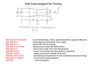
  • 1. N01 G91 G71 M03 S800 (incremental mode, metric, spindle start with a speed of 800 rpm) N02 G00 X1.0 (tool away from work piece 1mm, rapid) N03 G00 Z-1.0 (tool to left 1mm for facing) N04 G01 X-16.0 F200 (facing cut at a feed rate 200mm/min) N05 G00 Z1.0 (move tool to right 1mm from that position) N06 G00 X10.0 (move 10 mm away from the centre in x direction) N07G01 Z-36.0 (plane turning over a length of 35 mm) N08 G01 X5.0 Z-30.0 (simultaneous movement in X and Z directions for taper turning) N09 G00 X1.0 Z66.0 (move to the starting position) N10 M02 (end of program) G/M Code program for Turning
  • 3. Part will be defined in the Cartesian coordinate system as shown in fig.1. y z x
  • 4. 11/19/2021 Part Programming APT (Automatically Programmed Tool) is a software compiler for simplifying numerical control Programming. Developed by MIT in 1959 APT is the most widely used processor
  • 5. 11/19/2021 APT APT (Automatically Programmed Tool) is a software compiler for simplifying numerical control Programming. Developed by MIT in 1959 APT is the most widely used processor
  • 6. 11/19/2021 APT Characteristics • Three-dimensional unbounded surfaces and points are defined to represent the part to be made • Surfaces are defined in a X-Y-Z coordinate system • In Programming, the tool does all the moving; the part is stationary. • Linear interpolation is used for curved tool paths
  • 7. 11/19/2021 APT Statement Types (5) • Identification • Geometry • Motion • Postprocessor (feed, speed, coolant, … etc.) • Auxiliary (tool, tolerance, part, … etc.)
  • 8. The general format for geometric statements is: <Symbol> = Geometric Type/ Definitional Modifiers
  • 9. Point (POINT) PTA PTA = POINT/ 3,4,5 y x z (3, 4, 5)
  • 10. Point (POINT) PTB = POINT/ INTOF, LIN1, LIN2 LIN2 LIN1 PTB
  • 11. Point (POINT) PTD = POINT/ YSMALL, INTOF, LIN3, C1 PTD = POINT/ XSMALL, INTOF, LIN3, C1 x PTC PTD LIN3 C1 y PTC = POINT/ YLARGE, INTOF, LIN3, C1 PTC = POINT/ XLARGE, INTOF, LIN3, C1
  • 12. Point (POINT) PTE = POINT/ YLARGE, INTOF, C1, C2 PTE = POINT/ XLARGE, INTOF, C1, C2 y x C1 C2 PTE PTF PTF = POINT/ YSMALL, INTOF, C1, C2 PTF = POINT/ XSMALL, INTOF, C1, C2
  • 13. Point (POINT) PT7 = POINT/ CENTER, C6 C6 PT7 y x
  • 14. Point (POINT) PT11 = POINT/ P63, RADIUS, 7.3, ATANGLE, 27 27° P63 = 3.1, 6.7 PT11 y x 7.3
  • 15. Line (LINE) LIN1 = LINE/ P1, P2 LIN1 P1 P2 y x
  • 16. Line (LINE) LIN4 = LINE/ PT6, 15, -30, 3 PT6 L4 (15, -30, 3) y x
  • 17. Line (LINE) LIN10 = LINE/ 20, 3.5, 0.2, 31, 6.2, 1.3 (20, 3.5, 0.2) L10 (31, 6.2, 1.3) y x
  • 18. Line (LINE) L12 = LINE/ PT4, ATANGL, 20, XAXIS L14 = LINE/ PT1, ATANGL, 40 L15 = LINE/ 32, -3, 2, ATANGL, -15, XAXIS L16 = LINE/ PT3, ATANGL, 40, YAXIS y x L16 PT3 PT1 L14 L12 PT4 (32, -3, 2) L15 40° 40° 20° 15°
  • 19. Line (LINE) LIN = LINE/ POINT, ATANGL, ANGLE (in degrees), LINE P1 LINE1 LINE2 x y LINE2 = LINE/ P1, ATANGL, 30, LINE1 30°
  • 20. Line (LINE) LIN = LINE/ SLOPE, SLOPE VALUE, INTERC, MODIFIER, d where the slope value is y/x. The modifier options are [XAXIS, YAXIS], and d is the corresponding intercept value on the selected axis (i.e., modifier). x y (6,0) Point of X-Intercept LINE1 LINE1 = LINE/ SLOPE, 1, INTERC, XAXIS, 6
  • 21. Line (LINE) LIN = LINE/ ATANGL, DEGREES, INTERC, MODIFIER, d The modifier options are [XAXIS, YAXIS], and d is the corresponding intercept value on the selected axis (i.e., modifier). x y d LINE1  = 30° LINE1 = LINE/ ATANGL, 30, INTERC, XAXIS ,d
  • 22. Line (LINE) The LEFT & RIGHT modifier indicates whether the line is at the left or right tangent point, depending on how one looks at the circle from the point. L1 = LINE/ PT51, LEFT, TANTO, C11 L1 C11 PT51
  • 23. Line (LINE) L2 = LINE/ PT51, RIGHT, TANTO, C11 L1 = LINE/ PT40, RIGHT, TANTO, C11 L4 = LINE/ PT40, LEFT, TANTO, C11 Left Right PT51 L1 L3 L4 L2 Right Left PT40
  • 24. Line (LINE) L6 = LINE/ LEFT, TANTO, C3, LEFT, TANTO, C4 C3 L6 L9 C4 L8 L7 Right Left Left Right
  • 25. Line (LINE) L7 = LINE/ LEFT, TANTO, C3, RIGHT, TANTO, C4 L7 = LINE/ LEFT, TANTO, C4, RIGHT, TANTO, C3 C3 L6 L 9 C4 L8 L7 Right Left Lef t Right
  • 26. Line (LINE) L8 = LINE/ RIGHT, TANTO, C3, LEFT, TANTO, C4 C3 L6 L9 C4 L8 L7 Right Left Left Right
  • 27. Line (LINE) L9 = LINE/ RIGHT, TANTO, C3, RIGHT, TANTO, C4 L9 = LINE/ LEFT, TANTO, C4, LEFT, TANTO, C3 C3 L6 L9 C4 L8 L7 Right Left Left Right
  • 28. Line (LINE) LN3 = LINE/ PNT6, PARLEL, LN15 LN4 = LINE/ PNT5, PERPTO, LN13 y x PNT6 LN3 LN15 LN13 PNT5 LN4
  • 29. Plane (PLANE) LN5 = LINE/ INTOF, PLAN1, PLAN2 PLAN2 PLAN1 LN5
  • 30. Plane (PLANE) PLAN10 = PLANE/ PT6, PT12, PT15 PT15 PT12 PT6 PT4 y x z PLAN10 PLAN14 3.0
  • 31. Plane (PLANE) PLAN14 = PLANE/ PT4, PARLEL, PLAN10 PLAN14 = PLANE/ PARLEL, PLAN10, YSMALL, 3.0 PT15 PT12 PT6 PT4 y x z PLAN10 PLAN14 3.0
  • 32. Circle (CIRCLE) C1 = CIRCLE/ 3, 6, 5, 4.3 C1 = CIRCLE/ CENTER, PT3, RADIUS, 4.3 PT3 (3,6,5) C1 y x 4.3
  • 33. Circle (CIRCLE) C3 = CIRCLE/ CENTER, PT6, TANTO, LN4 C7 = CIRCLE/ CENTER, PT8, PT5 C3 y x LN4 PT6 C7 y x PT8 PT5
  • 34. Circle (CIRCLE) C3 = CIRCLE/ YLARGE, LN6, XLARGE, LN4, RADIUS, 2.0 C3 = CIRCLE/ XLARGE, LN6, YSMALL, LN4, RADIUS, 2.0 1.5 3.0 2.0 y x C1 C3 C2 LN4 LN6 YSMALL YLARGE XLARGE
  • 35. Circle (CIRCLE) C1 = CIRCLE/ YLARGE, LN6, YLARGE, LN4, RADIUS, 3.0 1.5 3.0 2.0 y x C1 C3 C2 LN4 LN6 YSMALL YLARGE XLARGE
  • 36. Circle (CIRCLE) C2 = CIRCLE/ XSMALL, LN6, XSMALL, LN4, RADIUS, 1.5 C2 = CIRCLE/ YLARGE, LN4, YSMALL, LN6, RADIUS, 1.5 1.5 3.0 2.0 y x C1 C3 C2 LN4 LN6 YSMALL YLARGE XLARGE
  • 37. Cylinder (CYLNDR) <Symbol> = CYLNDR/ <axis modifier>, TANTO, <1st plane>, <axis modifier>, TANTO, <2nd plane>, RADIUS, <radius value> The axis modifier depends on the relationship of the cylinder center point to the tangent point of the plane the modifier precedes.
  • 38. Cylinder (CYLNDR) CYL3 = CYLNDR/ XLARGE, TANTO, PLAN5, YSMALL, TANTO, PLAN10, RADIUS, 2.0 2.0 CYL3 PLAN5 PLAN10 z x y
  • 39. Geometry Example The top view of a plate is shown in the following figure. The outer shape of this plate is to be milled & the grid holes drilled. It is therefore necessary to define the geometry of the part, i.e. its outer shape & the location of the holes. 5.0 in. 4.0 in. Tangent point Tangent point 1.25 in. Side view Top view 1.0 in. 1.0 in. 1.0 in. 1.0 in. 0.4 in. 0.7 in. 0.7 in. 12 0.375 in. holes 0.5 in.
  • 40. Geometry Example PT1 = POINT/ 4, 5, 0 PT2 = POINT/ 5, 4.6, 0 PT3 = POINT/ 8, 4.6, 0 PT4 = POINT/ 8, 3.2, 0 PT5 = POINT/ 9, 3.75, 0 C1 = CIRCLE/ CENTER, PT5, RADIUS, 1.25 PT6 = POINT/ 4, 1, 0 L1 = LINE/ PT1, LEFT, TANTO, C1 L3 = LINE/ PT1, PT6 L2 = LINE/ PT6, RIGHT, TANTO, C1 PLAN1 = PLANE/ PT1, PT2, PT3 PLAN2 = PLANE/ PARLEL, PLAN1, ZSMALL, 0.5 PTN1 = PATERN/ LINEAR, PT2, PT3, 4 PTN2 = PATERN/ LINEAR, PT3, PT4, 3 PTN3 = PATERN/ COPY, PTN2, UNLIKE, ON, PTN1 PT1 = (4,5,0) L3 PT6 = (4,1,0) L2 L1 1.25 in. PT2 PT3 PT4 Z = 0 y x z x PT5 0.5 in.
  • 41. The Machining Plan Point- to- point: refers to operations requiring fast movement (straight- line motions) to a point followed by a manufacturing operation at that point. FROM/ <point location>: denotes that the point location is a starting point for the tool, with the end of the tool at that point. GOTO/ <point location>: refers to a rapid, straight- line move to the point location indicated. GODELTA/ <coordinate increments>: commands the tool to move incremental distance from the current position.
  • 42. The Machining Plan P1 = POINT/ 1.0, 2.7, 0.1 P2 = POINT/ 2.0, 2.7, 0.1 P3 = POINT/ 1.0, 2.0, 0.1 P0 = (0,4,0.1) 1.3 in. 0.7 in. 1.0 in. 1.0 in. P1 P2 P3 Z = 0.0 0.6 in.
  • 43. The Machining Plan FROM/ PO GOTO/ P1 GODELTA/ 0, 0, -0.8 GODELTA/ 0, 0, 0.8 GOTO/ P2 GODELTA/ 0, 0, -0.8 GODELTA/ 0, 0, 0.8 GOTO/ P3 GODELTA/ 0, 0, -0.8 GODELTA/ 0, 0, 0.8 GOTO/ PO P0 = (0,4,0.1) 1.3 in. 0.7 in. 1.0 in. 1.0 in. P1 P2 P3 Z = 0.0 0.6 in.
  • 44. The Machining Plan: Contouring: Part surface: the surface on which the end of the tool is riding. Drive surface: the surface against which the edge of the tool rides. Check surface: a surface at which the current tool motion is to stop.
  • 45. The Machining Plan cutter z x y Direction of cutter motion Drive surface Check surface Part surface
  • 47. The Machining Plan TANTO : A: GO/ TO, L1, TO, PL2, TANTO, C1 Start point L1 Drive surface A (TO, L1) B (PAST, L1) C1 Check surface y x B: GO/ PAST, L1, TO, PL2, TANTO, C1
  • 48. The Machining Plan Motion commands: GOLFT/ : Move left along the drive surface GORGT/ : Move right along the drive surface GOUP/ : Move up along the drive surface GODOWN/ : Move down along the drive surface GOFWD/ : Move forward from a tangent position GOBACK/ : Move backward from a tangent position
  • 49. The Machining Plan GORGT/ <drive surface>, <check surface> Start  A B  C  D  E  Start FROM/ START GO/ TO, L1, TO, PL1, ON, L3 GORGT/ L1, TANTO, C1 GOFWD/ C1, TANTO, L2 GOFWD/ L2, PAST, L3 GOLFT/ L3, PAST, L1 GOTO/ START z y x C B C1 Start A E D L3 L1 L2
  • 50. Machining Specifications Postprocessor commands for a particular machine tool are: MACHIN/ : used to specify the machine tool and call the postprocessor for that tool: MACHIN/ DRILL, 3 COOLNT/ : allows the coolant fluid to be turned on or off: COOLNT/ MIST COOLNT/ FLOOD COOLNT/ OFF
  • 51. Machining Specifications FEDRAT/ : specifies the feed rate for moving the tool along the part surface in inches per minute: FEDRAT/ 4.5 SPINDL/ : gives the spindle rotation speed in revolutions per minute: SPINDL/ 850 TURRET/ : can be used to call a specific tool from an automatic tool changer: TURRET/ 11
  • 52. Machining Specifications TOLERANCE SETTING: Nonlinear motion is accomplished in straight-line segments, and INTOL/ and OUTTOL/ statements dictate the number of straight-line segments to be generated. INTOL/ 0.0015 OUTTOL/ 0.001
  • 54. Machining Specifications PARTNO: identifies the part program and is inserted at the start of the program. CLPRINT: indicates that a cutter location printout is desired. CUTTER: specifies a cutter diameter for offset (rough versus finish cutting). If a milling cutter is 0.5 in. in diameter and we have CUTTER/ 0.6 then the tool will be offset from the finish cut by 0.05 in.
  • 55. APT Contouring Example PARTNO P1534 MACHIN/ MILL, 4 CLPRINT OUTTOL/ 0.0015 P0 = POINT/ 0, 0, 1.1 P1 = POINT/ 1, 1, 0.5 P2 = POINT/ 4, 3.5, 0.5 P3 = POINT/ 5.85, 2.85, 0.5 PL1 = PLANE/ P1, P2, P3 PL2 = PLANE/ PARLEL, PL1, ZSMALL, 0.5 P4 = POINT/ 5, 1.85, 0.5 P5 = POINT/ 2, 2.5, 0.5 C1 = CIRCLE/ CENTER, P4, RADIUS, 0.85 C2 = CIRCLE/ CENTER, P5, RADIUS, 1.0 L1 = LINE/ P1, RIGHT, TANTO, C1 L2 = LINE/ P3, LEFT, TANTO, C1 L3 = LINE/ P2, P3 L4 = LINE/ P2, RIGHT, TANTO, C2 L5 = LINE/ P1, LEFT, TANTO, C2 MILLS = MACRO/ CUT, SSP, FRT, CLT CUTTER/ CUT L1 L4 C2 L5 C1 L3 L2 P1 = (1,1,0.5) P2 P5 P4 x y Z = 0.5 Z = 0 z x P3
  • 56. APT Program P0 = POINT/ 0, -2, 0 P1 = POINT/ 0.312, 0.312, 0 P2 = POINT/ 4, 1, 0 C1 = CIRCLE/ CENTER, P1, RADIUS, 0.312 C2 = CIRCLE/ CENTER, P2, RADIUS, 1 L2 = LINE/ RIGHT, TANTO, C2, RIGHT, TANTO, C1 L1 = LINE/ LEFT, TANTO, C2, LEFT, TANTO, C1 PL1 = PLANE/ P0, P1, P2 FROM/ P0 GO/TO, L1, TO, PL1, TO, C2 GOLFT/ L1, TANTO, C1 GOFWD/ C1, PAST, L2 GOFWD/ L2, TANTO, C2 GOFWD/ C2, PAST, L1 GOTO/ P0 P1 P2 L2 L1 C1 C2 P0
  • 57. Geometric Statements of APT Program P0 = POINT/ -1, -1,3 P1 = POINT/ 0, 0 P2 = POINT/ 3, 0 P3 = POINT/ 4, 0 P4 = POINT/ 6.5, 5.5 C1 = CIRCLE/ CENTER, P3, RADIUS, 1 L0 = LINE/ P1, P2 L1 = LINE/ (POINT/ 5, 1), LEFT, TANTO, C1 L2 = LINE/ (POINT/ 7, 1), PERPTO, L1 C2 = CIRCLE/ CENTER, P4, RADIUS, 0.5 L3 = LINE/ (POINT/ 7, 1), RIGHT, TANTO, C2 L4 = LINE/ (POINT/ 5, 6), LEFT, TANTO, C2 C3 = CIRCLE/ CENTER, (POINT/ 4, 6), (POINT/ 3, 6) L5 = LINE/ (POINT/ 0, 6), (POINT/ 3, 6) L6 = LINE/ P1, PERPTO, L5 PL1 = PLANE/ P1, P2, P3 x y P0 P1 P2 P3 P4 C1 L0 L1 L2 L3 C2 C3 L5 L6
  • 58. Motion Statements of APT Program FROM/ P0 GO/ TO, L0, TO, PL1, TO, L6 GODLTA/ 0,0,-1 GORGT/ L0, TO, C1 GORGT/ C1, TANTO, L1 GOFWD/ L1, TO, L2 GORGT/ L2, PAST, L3 GOLFT/ L3, TANTO, C2 GOFWD/ C2, TANTO, L4 GOFWD/ L4, PAST, C3 GOLFT/ C3, PAST, L5 GOLFT/ L5, PAST, L6 GOLFT/ L6, PAST, L0 GODLTA/ 0,0,1 GOTO/ P0 x y P0 P1 P2 P3 P4 C1 L0 L1 L2 L3 C2 C3 L5 L6 L4 Thickness= 1inch.
  • 59. APT Program MACHIN/ MILL P0 = POINT/ 0, 0, 3 P1 = POINT/ 1, 0 L1 = LINE/ P1, SLOPE, 0 L2 = LINE/ P1, SLOPE, 90 L3 = LINE/ PARLEL, L1, YLARGE, 2 L4 = LINE/ (POINT/ 4, 2), SLOPE, 1, L3 L5 = LINE/ (POINT/ 6, 4), ATANGL, 270, L4 L6 = LINE/ (POINT/ 10, 0), PEPTO, L3 P2 = POINT/ INTOF, L3, L4 P3 = POINT/ INTOF, L4, L5 P4 = POINT/ INTOF, L5, L3 PL = PLANE/ P1, P2, P3 CUTTER/ 60 TOLER/ 0.1 SPINDL/ 200 COOLNT/ ON FEDRAT/ 20 P1 L1 L3 L3 L2 L6 L5 L4 P2 P4 P3 P0
  • 60. APT Program MACHIN/ MILL P0 = POINT/ 0, 0, 3 P1 = POINT/ 1, 0 L1 = LINE/ P1, SLOPE, 0 L2 = LINE/ P1, SLOPE, 90 L3 = LINE/ PARLEL, L1, YLARGE, 2 L4 = LINE/ (POINT/ 4, 2), SLOPE, 1, L3 L5 = LINE/ (POINT/ 6, 4), ATANGL, 270, L4 L6 = LINE/ (POINT/ 10, 0), PEPTO, L3 P2 = POINT/ INTOF, L3, L4 P3 = POINT/ INTOF, L4, L5 P4 = POINT/ INTOF, L5, L3 PL = PLANE/ P1, P2, P3 CUTTER/ 60 TOLER/ 0.1 SPINDL/ 200 COOLNT/ ON FEDRAT/ 20 L1 L3 L6 L2 L4 L5 P0