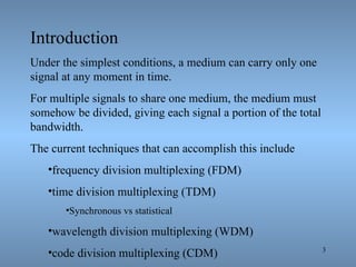
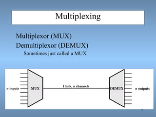
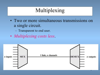
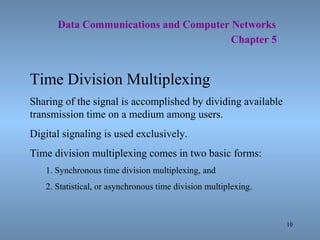
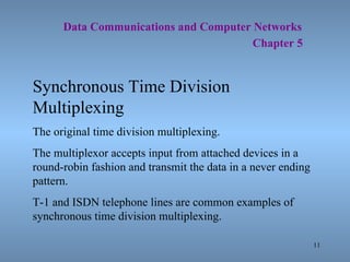
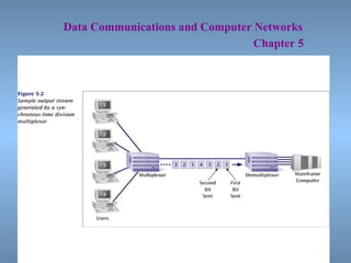
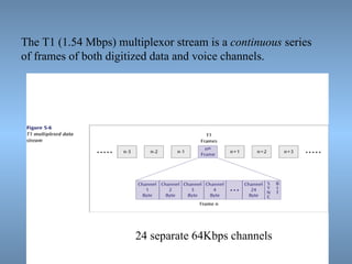
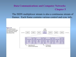
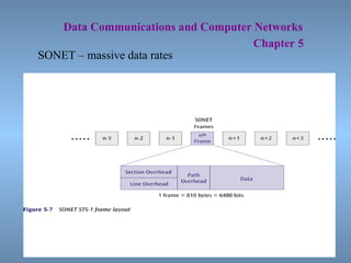
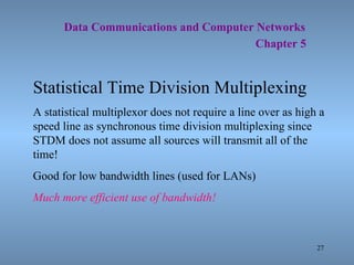
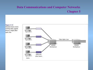
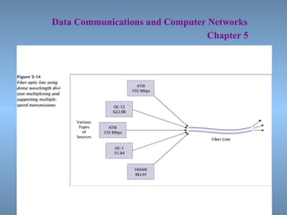
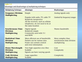
The document discusses different techniques for multiplexing, which is the sharing of a transmission medium by multiple signals. It describes frequency division multiplexing (FDM), time division multiplexing (TDM) including synchronous and statistical TDM, wavelength division multiplexing (WDM), and code division multiplexing (CDM). TDM techniques like T-1 and ISDN use synchronous multiplexing to transmit multiple digital signals over a single circuit simultaneously.
GENERAL DESCRIPTION OF THE PROBLEM , CONCEPT OF FREQUENCY CHANNELS, CO-CHANNEL iNTERFERENCE REDUCTION FACTOR , DESIRED C/I FROM A NORMAL CASE IN A OMNI DIRECTIONAL ANTENNA SYSTEM , CELL SPLITTING , CONSIDERATION OF THE COMPONENTS OF CELLULAR SYSTEM.
In the seven-layer OSI model of computer networking, media access control (MAC) data communication protocol is a sublayer of the data link layer (layer 2). The MAC sublayer provides addressing and channel access control mechanisms that make it possible for several terminals or network nodes to communicate within a multiple access network that incorporates a shared medium, e.g. an Ethernet network. The hardware that implements the MAC is referred to as a media access controller.
The MAC sublayer acts as an interface between the logical link control (LLC) sublayer and the network's physical layer. The MAC layer emulates a full-duplex logical communication channel in a multi-point network. This channel may provide unicast, multicast or broadcast communication service.
Data Communication & Computer Networks : Serial and parellel transmissionDr Rajiv Srivastava
These slides cover the fundamentals of data communication & networking. it covers Serial and Parallel transmission which are used in communication of data over transmission medium. It is useful for engineering students & also for the candidates who want to master data communication & computer networking.
Channelization is a multiple-access method in which the available bandwidth of a link is shared in time, frequency, or through code, between different stations. The three channelization protocols are FDMA, TDMA, and CDMA
The most fundamental digital modulation techniques are based on keying: PSK (phase-shift keying): a finite number of phases are used. FSK (frequency-shift keying): a finite number of frequencies are used. ... QAM (quadrature amplitude modulation): a finite number of at least two phases and at least two amplitudes are used.
This slide describe the techniques of digital modulation and Bandwidth Efficiency:
The first null bandwidth of M-ary PSK signals decrease as M increases while Rb is held constant.
Therefore, as the value of M increases, the bandwidth efficiency also increases.
In internetworking, Multiplexing is a process in which multiple data.pdfanupambedcovers
In internetworking, Multiplexing is a process in which multiple data channels are combined into
a single data or physical channel at the source. Multiplexing can be implemented at any of the
OSI layers. Conversely, demultiplexing is the process of separating multiplexed data channels at
the destination. In this way student data & class assignment data can be combined & separated.
Types of Multiplexing
There are two basic forms of multiplexing used:
Time Division Multiplexing
Time Division Multiplexing works by the multiplexor collecting and storing the incoming
transmissions from all of the slow lines connected to it and allocating a time slice on the fast link
to each in turn. The messages are sent down the high speed link one after the other. Each
transmission when received can be separated according to the time slice allocated.
Theoretically, the available speed of the fast link should at least be equal to the total of all of the
slow speeds coming into the multiplexor so that its maximum capacity is not exceeded.
Two ways of implementing TDM are:
Synchronous TDM
Synchronous TDM works by the muliplexor giving exactly the same amount of time to each
device connected to it. This time slice is allocated even if a device has nothing to transmit. This
is wasteful in that there will be many times when allocated time slots are not being used.
Therefore, the use of Synchronous TDM does not guarantee maximum line usage and efficiency.
Synchronous TDM is used in T1 and E1 connections.
Asynchronous TDM
Asynchronous TDM is a more flexible method of TDM. With Asynchronous TDM the length of
time allocated is not fixed for each device but time is given to devices that have data to transmit.
This version of TDM works by tagging each frame with an identification number to note which
device it belongs to. This may require more processing by the multiplexor and take longer,
however, the time saved by efficient and effective bandwidth utilization makes it worthwhile.
Asynchronous TDM allows more devices than there is physical bandwidth for.
This type of TDM is used in Asynchronous Transfer Mode (ATM) networks.
Frequency Division Multiplexing
Frequency Division Multiplexing (FDM) works by transmitting all of the signals along the same
high speed link simultaneously with each signal set at a different frequency. For FDM to work
properly frequency overlap must be avoided. Therefore, the link must have sufficient bandwidth
to be able to carry the wide range of frequencies required. The demultiplexor at the receiving end
works by dividing the signals by tuning into the appropriate frequency.
FDM operates in a similar way to radio broadcasting where a number of different stations will
broadcast simultaneously but on different frequencies. Listeners can then \"tune\" their radio so
that it captures the frequency or station they want.
FDM gives a total bandwidth greater than the combined bandwidth of the signals to be
transmitted. In order to prevent signal overlap t.
The tutorial is designed for all those readers who are planning or pursuing the CDMA course to make their career in this field. However, it is also meant for the common readers who simply want to understand − what is CDMA Technology?
CDMA Transmitter and Receiver Implementation Using FPGAIOSR Journals
Abstract: Code Division Multiple Access (CDMA) is a spread spectrum technique that uses neither frequency channels nor time slots. With CDMA, the narrow band message (typically digitized voice data) is multiplied by a large bandwidth signal that is a pseudo random noise code (PN code). All users in a CDMA system use the same frequency band and transmit simultaneously. The transmitted signal is recovered by correlating the received signal with the PN code used by the transmitter. The DS - CDMA is expected to be the major medium access technology in the future mobile systems owing to its potential capacity enhancement and the robustness against noise. The CDMA is uniquely featured by its spectrum-spreading randomization process employing a pseudo-noise (PN) sequence, thus is often called the spread spectrum multiple access (SSMA). As different CDMA users take different PN sequences, each CDMA receiver can discriminate and detect its own signal, by regarding the signals transmitted by other users as noise- like interferences. In this project direct sequence principle based CDMA transmitter and receiver is implemented in VHDL for FPGA. Modelsim 6.2(MXE) tool will be used for functional and logic verification at each block. The Xilinx synthesis technology (XST) of Xilinx ISE 9.2i tool will be used for synthesis of transmitter and receiver on FPGA Spartan 3E. Keywords: CDMA, DSSS, BPSK, GOLD code.
Data Communications (under graduate course) Lecture 4 of 5Randa Elanwar
Undergraduate course content:
Introduction: Types and sources of data, communication models, standards.
Data transmission: techniques, transmission media and characteristics.
Information theory: Information sources, information measure, entropy, source codes.
Line codes: characteristics, return-to-zero and non-return-to-zero signaling, bipolar alternate mark inversion, code (radix, redundancy and efficiency), important codes in current use, frequency spectra characteristics of common line codes, receiver clock synchronization, optical fiber systems, scramblers.
Modems: characteristics, modulation, equalization, control, V-standards.
Error Control: Transmission impairments, forward error control, linear block codes, feedback error control.
1. Chapter 5 Multiplexing : Sharing a Medium Data Communications and Computer Networks: A Business User’s Approach
2.
3.
4.
5.
6. Data Communications and Computer Networks Chapter 5 Frequency Division Multiplexing Assignment of non-overlapping frequency ranges to each “user” or signal on a medium. Thus, all signals are transmitted at the same time, each using different frequencies. A multiplexor accepts inputs and assigns frequencies to each device. The multiplexor is attached to a high-speed communications line. A corresponding multiplexor, or demultiplexor, is on the end of the high-speed line and separates the multiplexed signals.
7. Data Communications and Computer Networks Chapter 5
8. Data Communications and Computer Networks Chapter 5 Frequency Division Multiplexing Analog signaling is used to transmits the signals. Broadcast radio and television, cable television, and the AMPS cellular phone systems use frequency division multiplexing. This technique is the oldest multiplexing technique. Since it involves analog signaling, it is more susceptible to noise.
9.
10.
11. Data Communications and Computer Networks Chapter 5 Synchronous Time Division Multiplexing The original time division multiplexing. The multiplexor accepts input from attached devices in a round-robin fashion and transmit the data in a never ending pattern. T-1 and ISDN telephone lines are common examples of synchronous time division multiplexing.
12. Data Communications and Computer Networks Chapter 5
13. Data Communications and Computer Networks Chapter 5 Synchronous Time Division Multiplexing If one device generates data at a faster rate than other devices, then the multiplexor must either sample the incoming data stream from that device more often than it samples the other devices, or buffer the faster incoming stream. If a device has nothing to transmit, the multiplexor must still insert a piece of data from that device into the multiplexed stream.
14. Data Communications and Computer Networks Chapter 5
15. Data Communications and Computer Networks Chapter 5
16. Synchronous time division multiplexing So that the receiver may stay synchronized with the incoming data stream, the transmitting multiplexor can insert alternating 1s and 0s into the data stream.
17.
18. The T1 (1.54 Mbps) multiplexor stream is a continuous series of frames of both digitized data and voice channels. 24 separate 64Kbps channels
19. Data Communications and Computer Networks Chapter 5 The ISDN multiplexor stream is also a continuous stream of frames. Each frame contains various control and sync info.
20. Data Communications and Computer Networks Chapter 5 SONET – massive data rates
21.
22. Data Communications and Computer Networks Chapter 5 Statistical Time Division Multiplexing A statistical multiplexor transmits only the data from active workstations ( or why work when you don’t have to ). If a workstation is not active, no space is wasted on the multiplexed stream. A statistical multiplexor accepts the incoming data streams and creates a frame containing only the data to be transmitted.
23. Data Communications and Computer Networks Chapter 5
24. Data Communications and Computer Networks Chapter 5 To identify each piece of data, an address is included.
25. Data Communications and Computer Networks Chapter 5 If the data is of variable size, a length is also included.
26. Data Communications and Computer Networks Chapter 5 More precisely, the transmitted frame contains a collection of data groups.
27. Data Communications and Computer Networks Chapter 5 Statistical Time Division Multiplexing A statistical multiplexor does not require a line over as high a speed line as synchronous time division multiplexing since STDM does not assume all sources will transmit all of the time! Good for low bandwidth lines (used for LANs) Much more efficient use of bandwidth!
28. Data Communications and Computer Networks Chapter 5 Wavelength Division Multiplexing (WDM) Give each message a different wavelength (frequency) Easy to do with fiber optics and optical sources
29. Dense Wavelength Division Multiplexing (DWDM) Dense wavelength division multiplexing is often called just wavelength division multiplexing Dense wavelength division multiplexing multiplexes multiple data streams onto a single fiber optic line. Different wavelength lasers (called lambdas) transmit the multiple signals. Each signal carried on the fiber can be transmitted at a different rate from the other signals. Dense wavelength division multiplexing combines many (30, 40, 50, 60, more?) onto one fiber.
30. Data Communications and Computer Networks Chapter 5
31. Data Communications and Computer Networks Chapter 5
32.
33. Data Communications and Computer Networks Chapter 5 Code Division Multiplexing An advanced technique that allows multiple devices to transmit on the same frequencies at the same time. Each mobile device is assigned a unique 64-bit code (chip spreading code) To send a binary 1, mobile device transmits the unique code To send a binary 0, mobile device transmits the inverse of code
34. Data Communications and Computer Networks Chapter 5 Code Division Multiplexing Receiver gets summed signal, multiplies it by receiver code, adds up the resulting values Interprets as a binary 1 if sum is near +64 Interprets as a binary 0 if sum is near –64
35.
36. Data Communications and Computer Networks Chapter 5 Business Multiplexing In Action XYZ Corporation has two buildings separated by a distance of 300 meters. A 3-inch diameter tunnel extends underground between the two buildings. Building A has a mainframe computer and Building B has 66 terminals. List some efficient techniques to link the two buildings.
37. Data Communications and Computer Networks Chapter 5
38. Data Communications and Computer Networks Chapter 5 Possible Solutions Connect each terminal to the mainframe computer using separate point-to-point lines. Connect all the terminals to the mainframe computer using one multipoint line. Connect all the terminal outputs and use microwave transmissions to send the data to the mainframe. Collect all the terminal outputs using multiplexing and send the data to the mainframe computer using a conducted line.