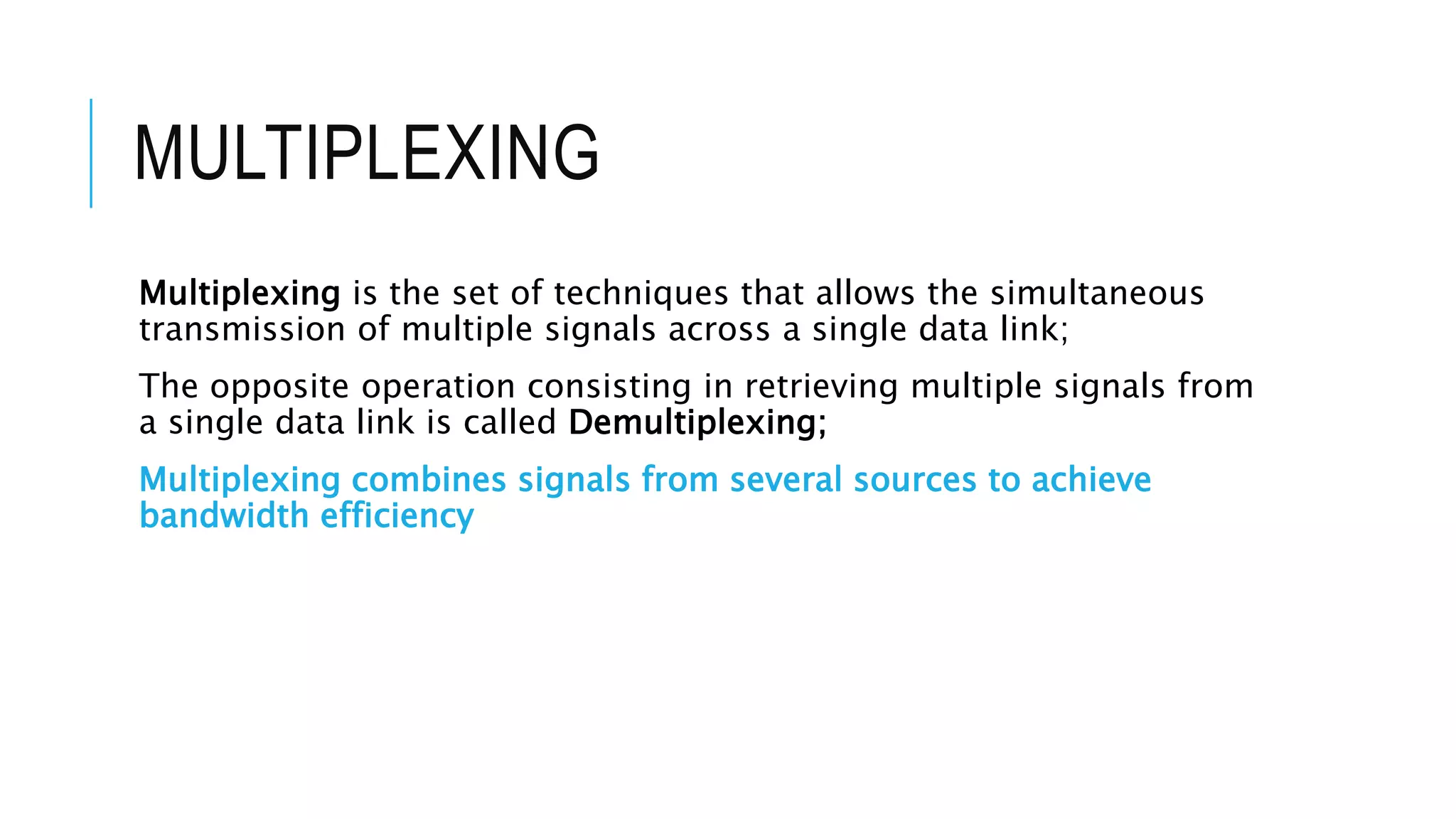
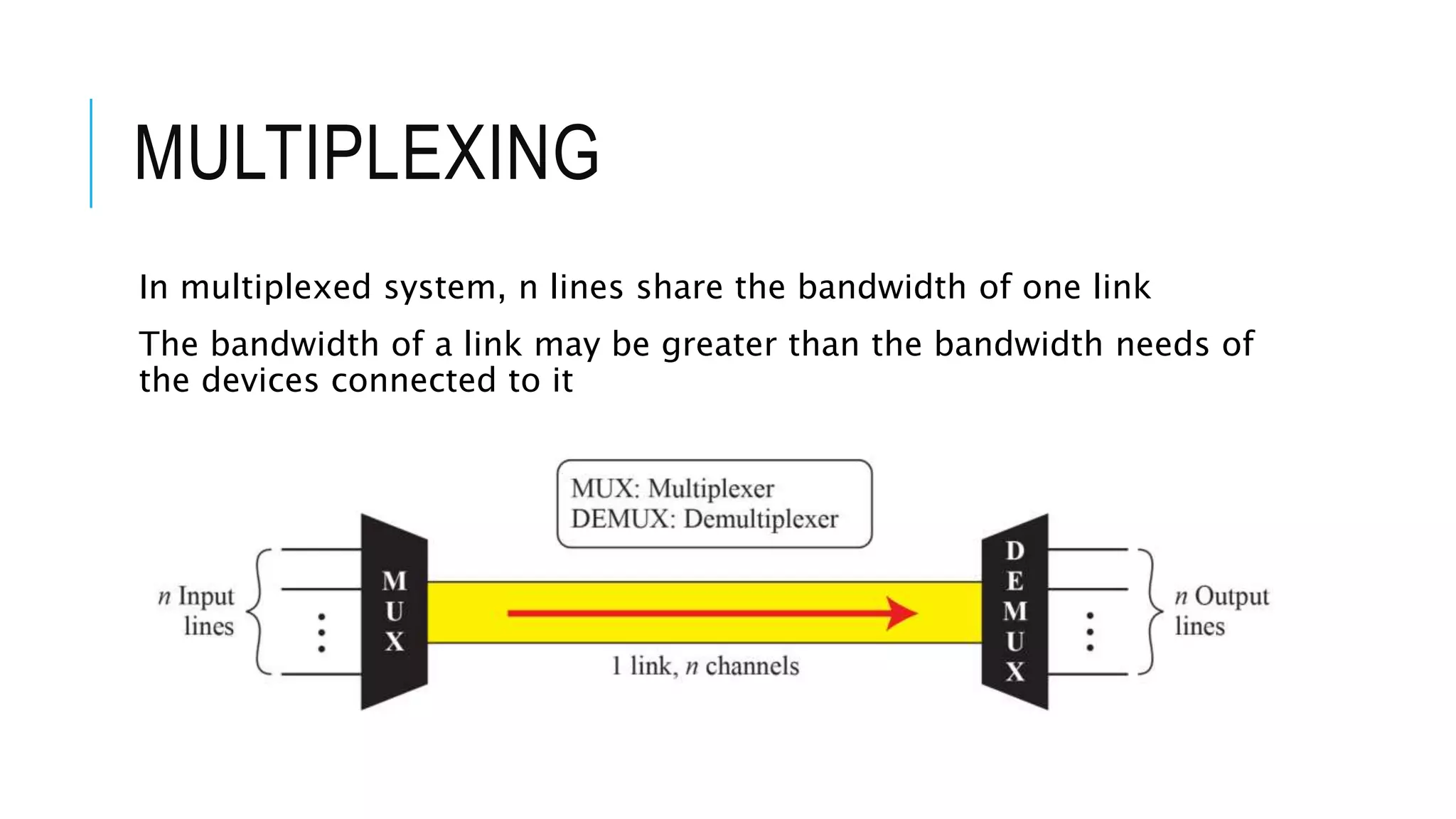
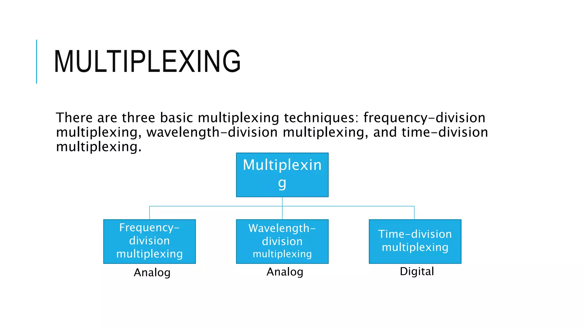
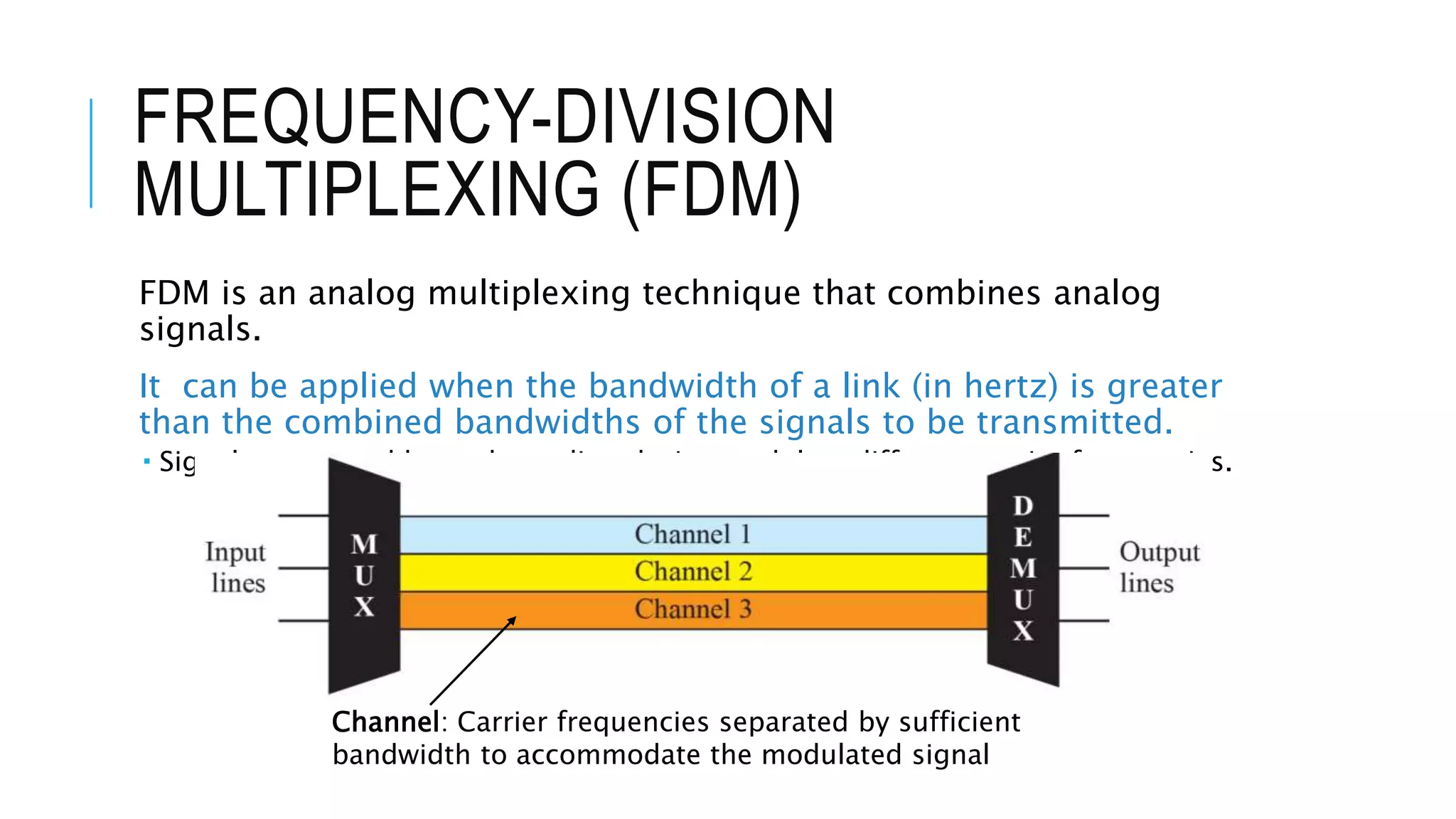
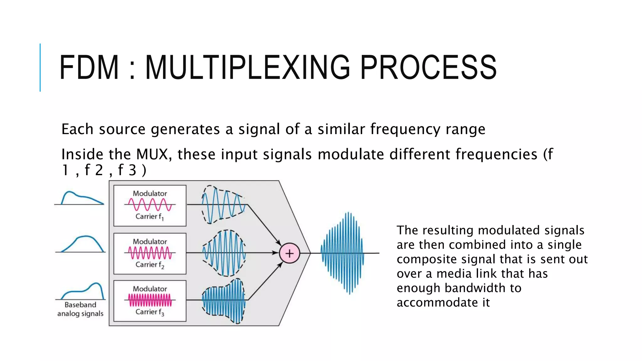
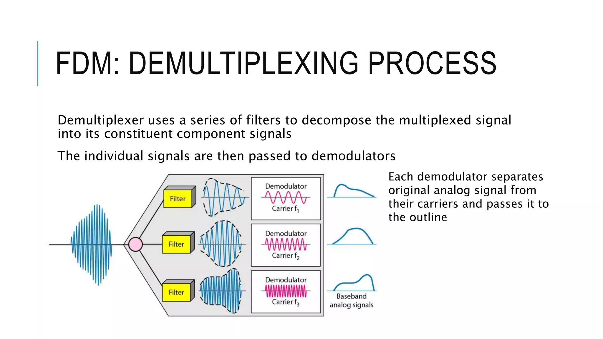
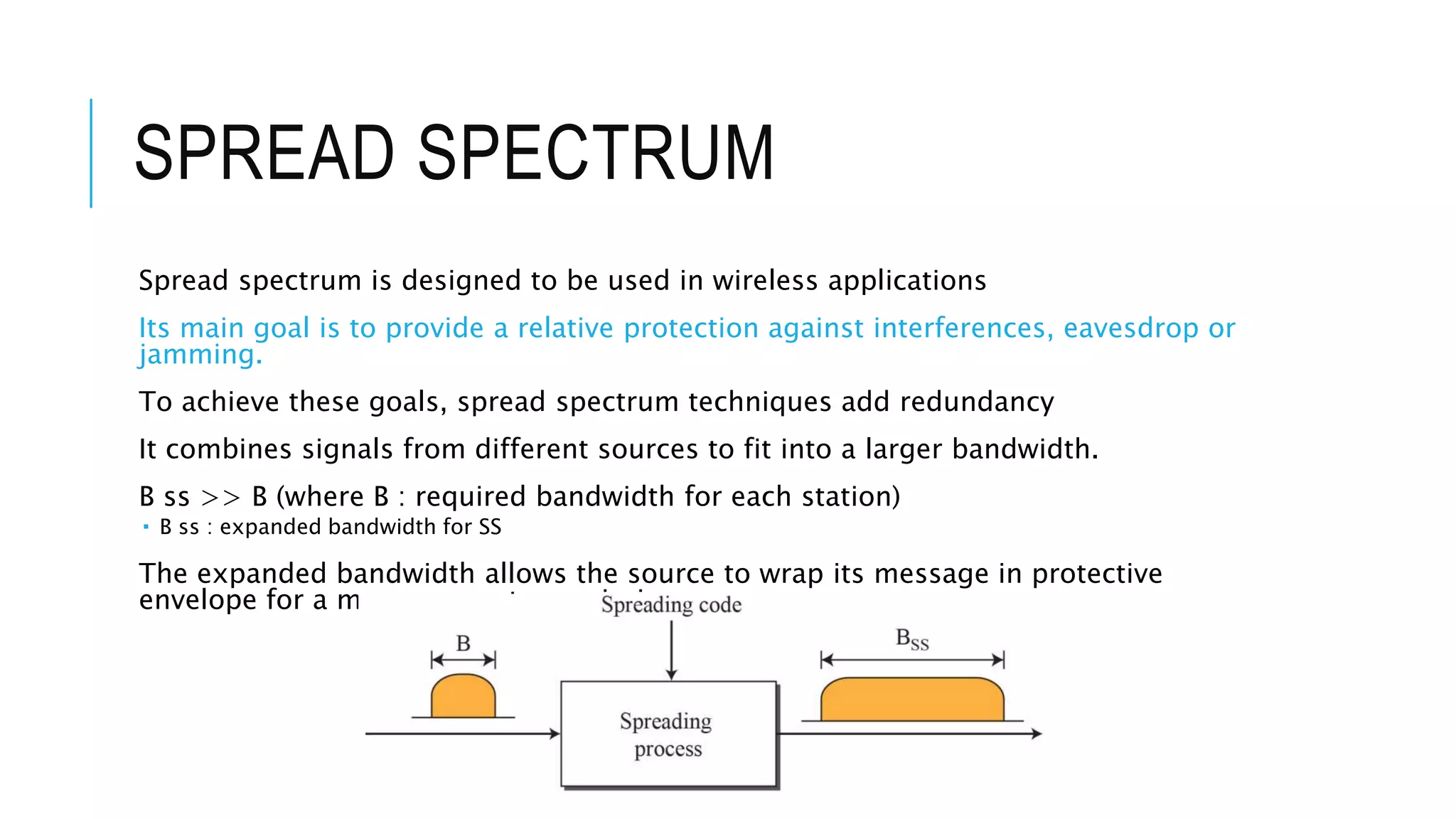
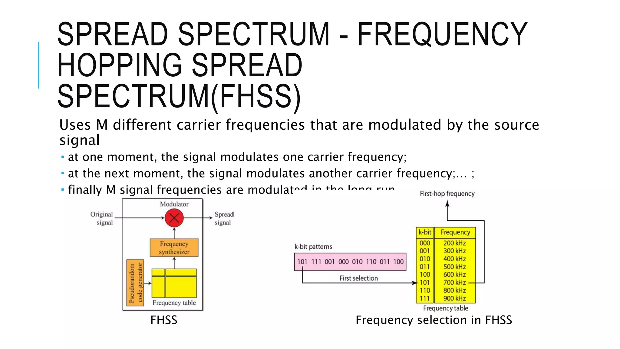
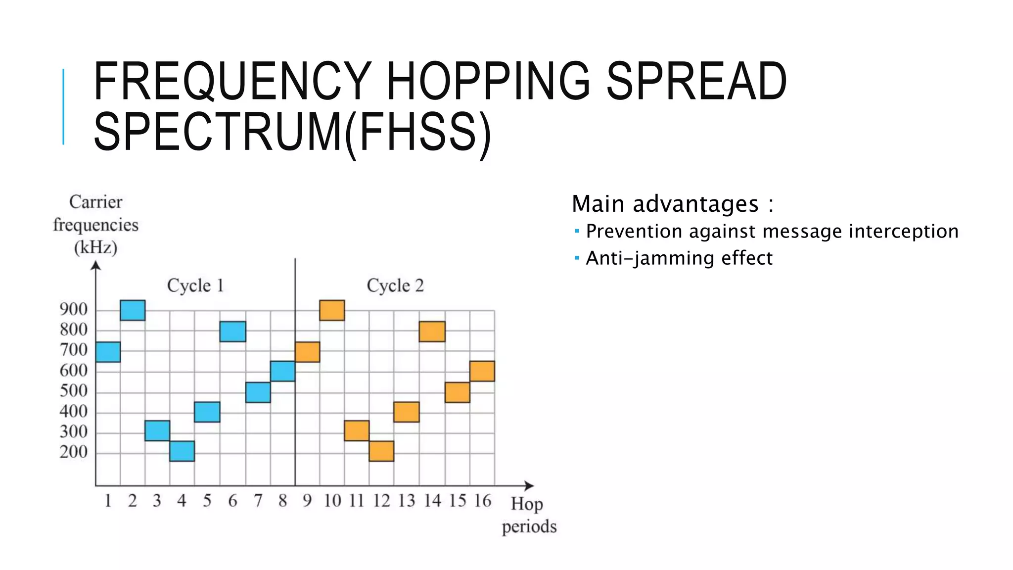
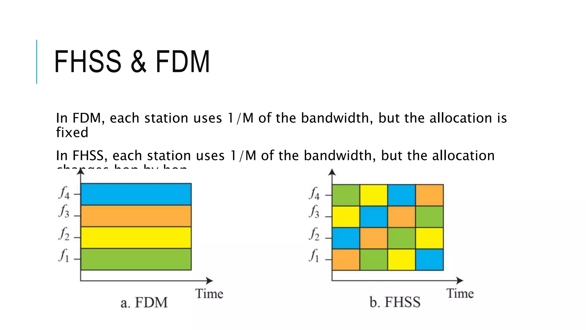
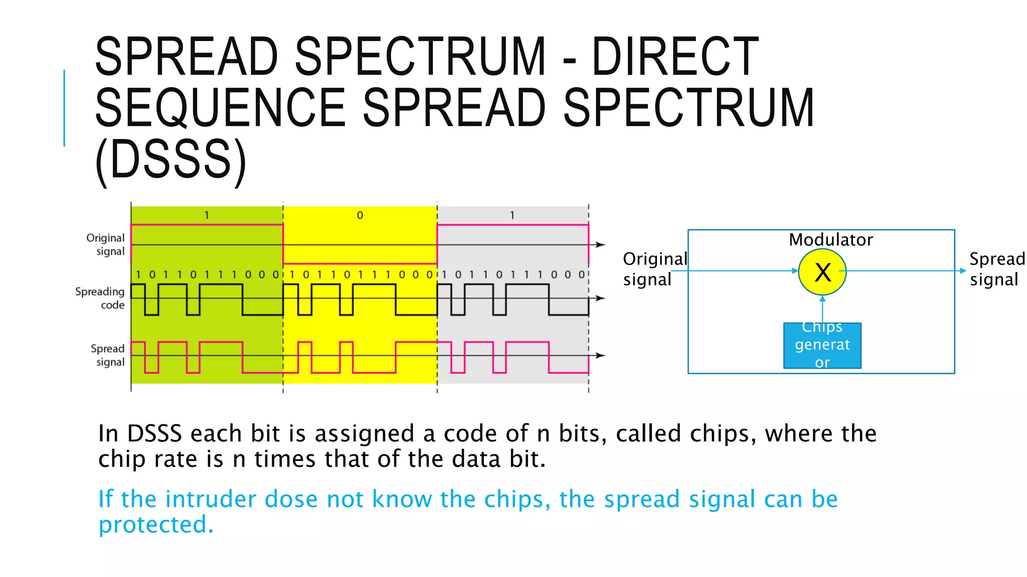
CH6 - BANDWIDTH
UTILISATION:
MULTIPLEXING AND
SPREADING
FDM, TDM, WDM, Spread
Spectrum, FHSS, DSSS,
Multiplexing,
Demultiplexing, Framing…
By Alban
INTRODUCTION
Bandwidth utilization is the wise use of available bandwidth to achieve
specific goals. Efficiency can be achieved by multiplexing; privacy and
anti-jamming can be achieved by spreading.
MULTIPLEXING
Multiplexing is the set of techniques that allows the simultaneous
transmission of multiple signals across a single data link;
The opposite operation consisting in retrieving multiple signals from
a single data link is called Demultiplexing;
Multiplexing combines signals from several sources to achieve
bandwidth efficiency
MULTIPLEXING
In multiplexed system, n lines share the bandwidth of one link
The bandwidth of a link may be greater than the bandwidth needs of
the devices connected to it
MULTIPLEXING
There are three basic multiplexing techniques: frequency-division
multiplexing, wavelength-division multiplexing, and time-division
multiplexing.
Multiplexin
g
Frequency-
division
multiplexing
Wavelength-
division
multiplexing
Time-division
multiplexing
Analog Analog Digital
FREQUENCY-DIVISION
MULTIPLEXING (FDM)
FDM is an analog multiplexing technique that combines analog
signals.
It can be applied when the bandwidth of a link (in hertz) is greater
than the combined bandwidths of the signals to be transmitted.
 Signals generated by each sending device modulate different carrier frequencies.
Channel: Carrier frequencies separated by sufficient
bandwidth to accommodate the modulated signal
FDM : MULTIPLEXING PROCESS
Each source generates a signal of a similar frequency range
Inside the MUX, these input signals modulate different frequencies (f
1 , f 2 , f 3 )
The resulting modulated signals
are then combined into a single
composite signal that is sent out
over a media link that has
enough bandwidth to
accommodate it
FDM: DEMULTIPLEXING PROCESS
Demultiplexer uses a series of filters to decompose the multiplexed signal
into its constituent component signals
The individual signals are then passed to demodulators
Each demodulator separates
original analog signal from
their carriers and passes it to
the outline
FDM
Even though FDM is analog muxing, FDM can be used to send digital
signals
 Digital data can be converted to an analog signal before FMS’s muxing
WAVELENGTH-DIVISION
MULTIPLEXING (WDM)
Conceptually same than FDM. Instead involves optical signal.
WDM is an analog multiplexing technique to combine optical signals.
 Designed to use the high-data-rate capability of fiber-optic cable
 The main idea is to combine different signals of different frequencies same as FDM
Very narrow bands of light from different sources are combined to
make a wider band of light.
WDM is designed to use the high bandwidth capability of fiber-
WAVELENGTH-DIVISION
MULTIPLEXING (WDM)
A multiplexer combines several input beams of light, each containing
a narrow band of frequencies, into one output beam of a wider band
of frequencies
A demultiplexer reverses the process
Use prisms as MUX and DEMUX
WAVELENGTH-DIVISION
MULTIPLEXING (WDM)
WDM is used in SONET (ch.14)
Dense WDM : muxing a very large number of channels by spacing
channels very close to one another
TIME-DIVISION MULTIPLEXING
(TDM)
Instead of sharing a portion of the bandwidth as in FDM, time is shared in TDM.
Each connection occupies a portion of time in the link
TDM is a digital multiplexing technique for combining several low-rate channels
into one high-rate one.
In TDM one data is sent using the full bandwidth available in the medium
Frame
Time slot
TIME-DIVISION MULTIPLEXING
2 types of schemes
 Synchronous TDM
 Statistical TDM
SYNCHRONOUS TDM
In synchronous TDM, the data rate of the link is n times faster, and
the unit duration is n times shorter.
 In synchronous TDM, a round of data units from each input connection is collected
into a frame
 For n connections, a frame is divided into n time slots and one slot is allocated for
each unit
Time slots are grouped into
frames and a frame consists of
one complete cycle of time slots
SYNCHRONOUS TDM-
INTERLEAVING
The process of taking a group of bits from each input line for multiplexing
is called interleaving
TDM has two fast-rotating switches, one on the MUXside and other on the
side
 The switches are synchronized and rotate at the same speed
 On MUX, as the switch opens in front of a connection, that connection has opportunity to
send a unit onto the path -> interleaving
If a source does not
have data to send,
the corresponding
slot in the output
frame is empty.
TDM - DATA RATE MANAGEMENT
Set of techniques used to handle a disparity in the input data rates
20
kpbs20
kpbs40
kpbs40
kpbs40
kpbs
40
kpbs
160
kpbs
50
kpbs
25
kpbs25
kpbs25
kpbs
125
kpbs
25
kpbs
25
kpbs
50
kpbs
50
kpbs
46
kpbs
150
kpbs
50
kpbs
Pulse
stuffing
Multilevel multiplexing is a technique
used when the data rate of an input
line is a multiple of others.
Multiple-Slot Allocation - Sometimes it
is more efficient to allot more than one
slot in
a frame to a single input line.
Pulse Stuffing - used to make the
highest input data rate the dominant
data rate and then add dummy bits to
the input lines with lower rates. This
will increase their rates.
TDM – FRAME SYNCHRONIZATION
If the multiplexer and the demultiplexer are not synchronized, a bit
belonging to one channel may be received by the wrong channel.
To solve this problem, in synchronous TDM, one or more
synchronization bits are usually added to the beginning of each
frame.
STATISTICAL TIME-DIVISION
MULTIPLEXING
In statistical time-division multiplexing, slots are dynamically
allocated to improve bandwidth efficiency.
 Only when an input line has a data to send is it given a slot in the output frame
 A slot needs to carry data as well as the address of the destination
SPREAD SPECTRUM
Spread spectrum is designed to be used in wireless applications
Its main goal is to provide a relative protection against interferences, eavesdrop or
jamming.
To achieve these goals, spread spectrum techniques add redundancy
It combines signals from different sources to fit into a larger bandwidth.
B ss >> B (where B : required bandwidth for each station)
 B ss : expanded bandwidth for SS
The expanded bandwidth allows the source to wrap its message in protective
envelope for a more secure transmission
SPREAD SPECTRUM - FREQUENCY
HOPPING SPREAD
SPECTRUM(FHSS)
Uses M different carrier frequencies that are modulated by the source
signal
 at one moment, the signal modulates one carrier frequency;
 at the next moment, the signal modulates another carrier frequency;… ;
 finally M signal frequencies are modulated in the long run
FHSS Frequency selection in FHSS
FREQUENCY HOPPING SPREAD
SPECTRUM(FHSS)
Main advantages :
 Prevention against message interception
 Anti-jamming effect
FHSS & FDM
In FDM, each station uses 1/M of the bandwidth, but the allocation is
fixed
In FHSS, each station uses 1/M of the bandwidth, but the allocation
changes hop by hop
SPREAD SPECTRUM - DIRECT
SEQUENCE SPREAD SPECTRUM
(DSSS)
In DSSS each bit is assigned a code of n bits, called chips, where the
chip rate is n times that of the data bit.
If the intruder dose not know the chips, the spread signal can be
protected.
X
Original
signal
Spread
signal
Chips
generat
or
Modulator
Ch6 bandwidth utilisation multiplexing and spreading

Ch6 bandwidth utilisation multiplexing and spreading

  • 1.
    CH6 - BANDWIDTH UTILISATION: MULTIPLEXINGAND SPREADING FDM, TDM, WDM, Spread Spectrum, FHSS, DSSS, Multiplexing, Demultiplexing, Framing… By Alban
  • 2.
    INTRODUCTION Bandwidth utilization isthe wise use of available bandwidth to achieve specific goals. Efficiency can be achieved by multiplexing; privacy and anti-jamming can be achieved by spreading.
  • 3.
    MULTIPLEXING Multiplexing is theset of techniques that allows the simultaneous transmission of multiple signals across a single data link; The opposite operation consisting in retrieving multiple signals from a single data link is called Demultiplexing; Multiplexing combines signals from several sources to achieve bandwidth efficiency
  • 4.
    MULTIPLEXING In multiplexed system,n lines share the bandwidth of one link The bandwidth of a link may be greater than the bandwidth needs of the devices connected to it
  • 5.
    MULTIPLEXING There are threebasic multiplexing techniques: frequency-division multiplexing, wavelength-division multiplexing, and time-division multiplexing. Multiplexin g Frequency- division multiplexing Wavelength- division multiplexing Time-division multiplexing Analog Analog Digital
  • 6.
    FREQUENCY-DIVISION MULTIPLEXING (FDM) FDM isan analog multiplexing technique that combines analog signals. It can be applied when the bandwidth of a link (in hertz) is greater than the combined bandwidths of the signals to be transmitted.  Signals generated by each sending device modulate different carrier frequencies. Channel: Carrier frequencies separated by sufficient bandwidth to accommodate the modulated signal
  • 7.
    FDM : MULTIPLEXINGPROCESS Each source generates a signal of a similar frequency range Inside the MUX, these input signals modulate different frequencies (f 1 , f 2 , f 3 ) The resulting modulated signals are then combined into a single composite signal that is sent out over a media link that has enough bandwidth to accommodate it
  • 8.
    FDM: DEMULTIPLEXING PROCESS Demultiplexeruses a series of filters to decompose the multiplexed signal into its constituent component signals The individual signals are then passed to demodulators Each demodulator separates original analog signal from their carriers and passes it to the outline
  • 9.
    FDM Even though FDMis analog muxing, FDM can be used to send digital signals  Digital data can be converted to an analog signal before FMS’s muxing
  • 10.
    WAVELENGTH-DIVISION MULTIPLEXING (WDM) Conceptually samethan FDM. Instead involves optical signal. WDM is an analog multiplexing technique to combine optical signals.  Designed to use the high-data-rate capability of fiber-optic cable  The main idea is to combine different signals of different frequencies same as FDM Very narrow bands of light from different sources are combined to make a wider band of light. WDM is designed to use the high bandwidth capability of fiber-
  • 11.
    WAVELENGTH-DIVISION MULTIPLEXING (WDM) A multiplexercombines several input beams of light, each containing a narrow band of frequencies, into one output beam of a wider band of frequencies A demultiplexer reverses the process Use prisms as MUX and DEMUX
  • 12.
    WAVELENGTH-DIVISION MULTIPLEXING (WDM) WDM isused in SONET (ch.14) Dense WDM : muxing a very large number of channels by spacing channels very close to one another
  • 13.
    TIME-DIVISION MULTIPLEXING (TDM) Instead ofsharing a portion of the bandwidth as in FDM, time is shared in TDM. Each connection occupies a portion of time in the link TDM is a digital multiplexing technique for combining several low-rate channels into one high-rate one. In TDM one data is sent using the full bandwidth available in the medium Frame Time slot
  • 14.
    TIME-DIVISION MULTIPLEXING 2 typesof schemes  Synchronous TDM  Statistical TDM
  • 15.
    SYNCHRONOUS TDM In synchronousTDM, the data rate of the link is n times faster, and the unit duration is n times shorter.  In synchronous TDM, a round of data units from each input connection is collected into a frame  For n connections, a frame is divided into n time slots and one slot is allocated for each unit Time slots are grouped into frames and a frame consists of one complete cycle of time slots
  • 16.
    SYNCHRONOUS TDM- INTERLEAVING The processof taking a group of bits from each input line for multiplexing is called interleaving TDM has two fast-rotating switches, one on the MUXside and other on the side  The switches are synchronized and rotate at the same speed  On MUX, as the switch opens in front of a connection, that connection has opportunity to send a unit onto the path -> interleaving If a source does not have data to send, the corresponding slot in the output frame is empty.
  • 17.
    TDM - DATARATE MANAGEMENT Set of techniques used to handle a disparity in the input data rates 20 kpbs20 kpbs40 kpbs40 kpbs40 kpbs 40 kpbs 160 kpbs 50 kpbs 25 kpbs25 kpbs25 kpbs 125 kpbs 25 kpbs 25 kpbs 50 kpbs 50 kpbs 46 kpbs 150 kpbs 50 kpbs Pulse stuffing Multilevel multiplexing is a technique used when the data rate of an input line is a multiple of others. Multiple-Slot Allocation - Sometimes it is more efficient to allot more than one slot in a frame to a single input line. Pulse Stuffing - used to make the highest input data rate the dominant data rate and then add dummy bits to the input lines with lower rates. This will increase their rates.
  • 18.
    TDM – FRAMESYNCHRONIZATION If the multiplexer and the demultiplexer are not synchronized, a bit belonging to one channel may be received by the wrong channel. To solve this problem, in synchronous TDM, one or more synchronization bits are usually added to the beginning of each frame.
  • 19.
    STATISTICAL TIME-DIVISION MULTIPLEXING In statisticaltime-division multiplexing, slots are dynamically allocated to improve bandwidth efficiency.  Only when an input line has a data to send is it given a slot in the output frame  A slot needs to carry data as well as the address of the destination
  • 20.
    SPREAD SPECTRUM Spread spectrumis designed to be used in wireless applications Its main goal is to provide a relative protection against interferences, eavesdrop or jamming. To achieve these goals, spread spectrum techniques add redundancy It combines signals from different sources to fit into a larger bandwidth. B ss >> B (where B : required bandwidth for each station)  B ss : expanded bandwidth for SS The expanded bandwidth allows the source to wrap its message in protective envelope for a more secure transmission
  • 21.
    SPREAD SPECTRUM -FREQUENCY HOPPING SPREAD SPECTRUM(FHSS) Uses M different carrier frequencies that are modulated by the source signal  at one moment, the signal modulates one carrier frequency;  at the next moment, the signal modulates another carrier frequency;… ;  finally M signal frequencies are modulated in the long run FHSS Frequency selection in FHSS
  • 22.
    FREQUENCY HOPPING SPREAD SPECTRUM(FHSS) Mainadvantages :  Prevention against message interception  Anti-jamming effect
  • 23.
    FHSS & FDM InFDM, each station uses 1/M of the bandwidth, but the allocation is fixed In FHSS, each station uses 1/M of the bandwidth, but the allocation changes hop by hop
  • 24.
    SPREAD SPECTRUM -DIRECT SEQUENCE SPREAD SPECTRUM (DSSS) In DSSS each bit is assigned a code of n bits, called chips, where the chip rate is n times that of the data bit. If the intruder dose not know the chips, the spread signal can be protected. X Original signal Spread signal Chips generat or Modulator

Editor's Notes

  • #3 In multiplexing, our goal is efficiency; we combine several channels into one. In spreading, our goals are privacy and antijamming.
  • #4 If the bandwidth of a link is greater than the bandwidth needs of the devices connected to it, the bandwidth is wasted. An efficient system maximizes the utilization of all resources; bandwidth is one of the most precious resources we have in data communications.
  • #7 In FDM, signals generated by each sending device modulate different carrier frequencies. These modulated signals are then combined into a single composite signal that can be transported by the link. The word link refers to the physical path. The word channel refers to the portion of a link that carries a transmis- sion between a given pair of lines. Another use is to carry separate serial bits or segments of a higher rate signal in parallel.
  • #10 Chap 5
  • #11  We want to combine multiple light sources into one single light at the multiplexer and do the reverse at the demultiplexer.
  • #12 A prism bends a beam of light based on the angle of incidence and the frequency
  • #16 If the duration of the input unit is T, o the duration of each slot is T/n and o the duration of each frame is T
  • #18 Pulse Stuffing is used when neither of the first 2 mentioned techniques can’t be used due to the fact that the bit rates of sources are not multiples of each other.
  • #19  Synchronization bits These bits, called framing bits, follow a pattern, frame to frame, that allows the demultiplexer to synchronize with the incoming stream so that it can separate the time slots accurately. In most cases, this synchronization information consists of 1 bit per frame, alternating between 0 and 1.
  • #20 Digital Signal Service o Telephone companies i In synchronous TDM, there is no need for addressing; synchronization and preassigned relationships between the inputs and outputs serve as an address. In statistical multiplexing, there is no fixed relationship between the inputs and outputs because there are no preassigned or reserved slots. We need to include the address of the receiver inside each slot to show where it is to be delivered. Bandwidth In statistical TDM, the capacity of the link is normally less than the sum of the capacities of each channel. The designers of statistical TDM define the capacity of the link based on the statistics of the load for each channel. If on average only x percent of the input slots are filled, the capacity of the link reflects this. Of course, during peak times, some slots need to wait.
  • #23 If an intruder tries to intercept the transmitted signal, she(?) can only access a small piece of data since she dose not know the spreading sequence to quickly adapt herself to the next hop A malicious sender may be able to send noise to jam the signal for one hopping period (randomly) but not for the whole period