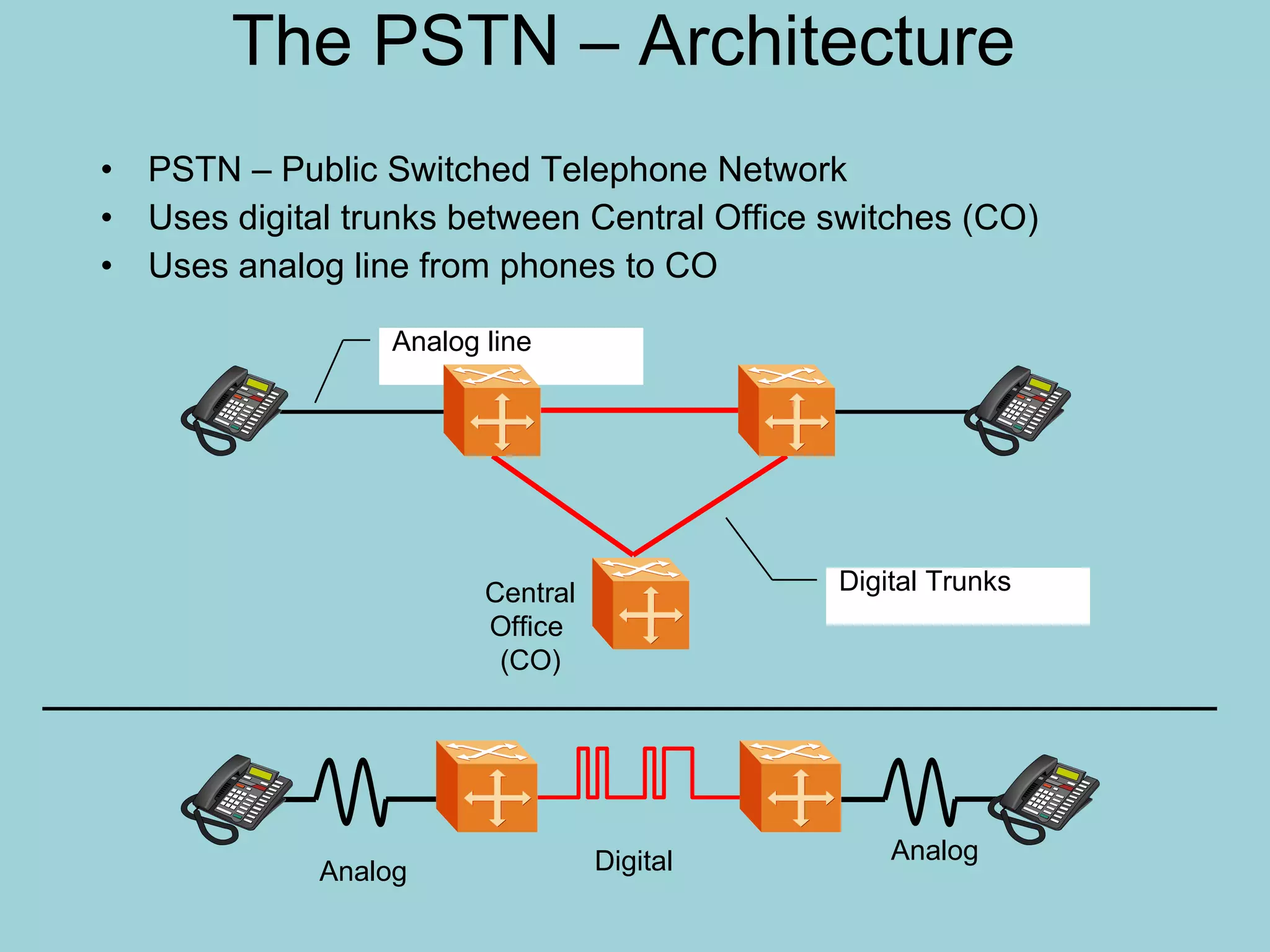
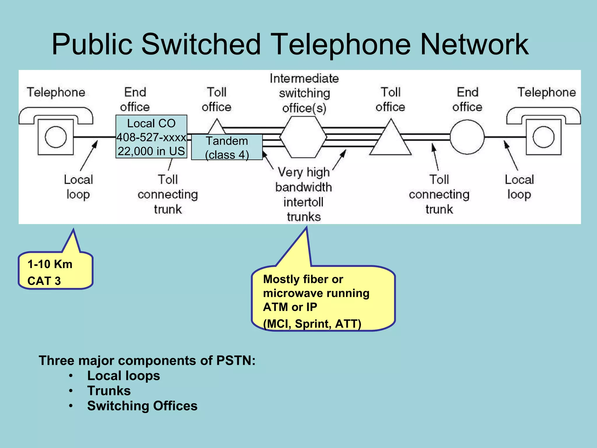
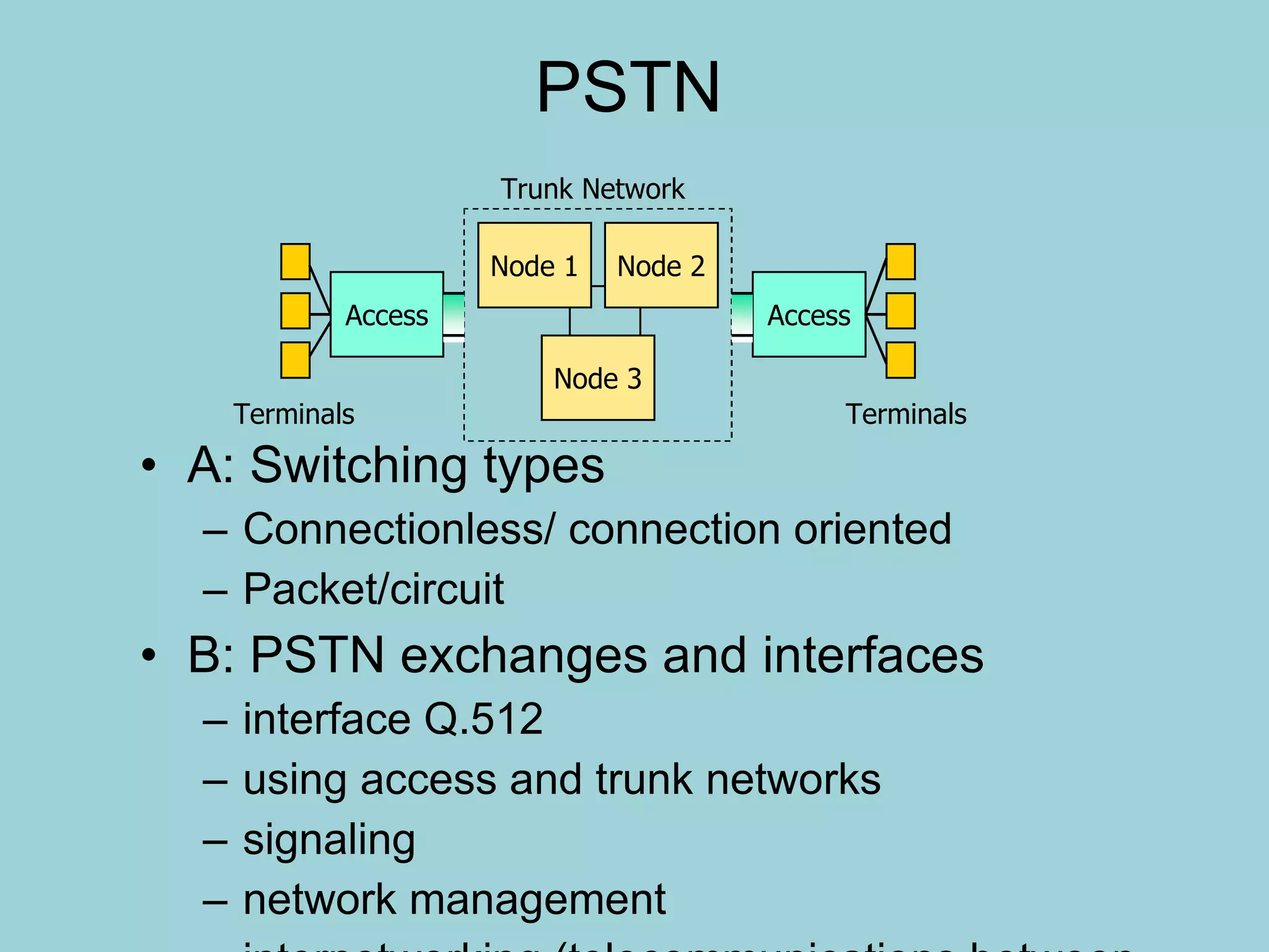
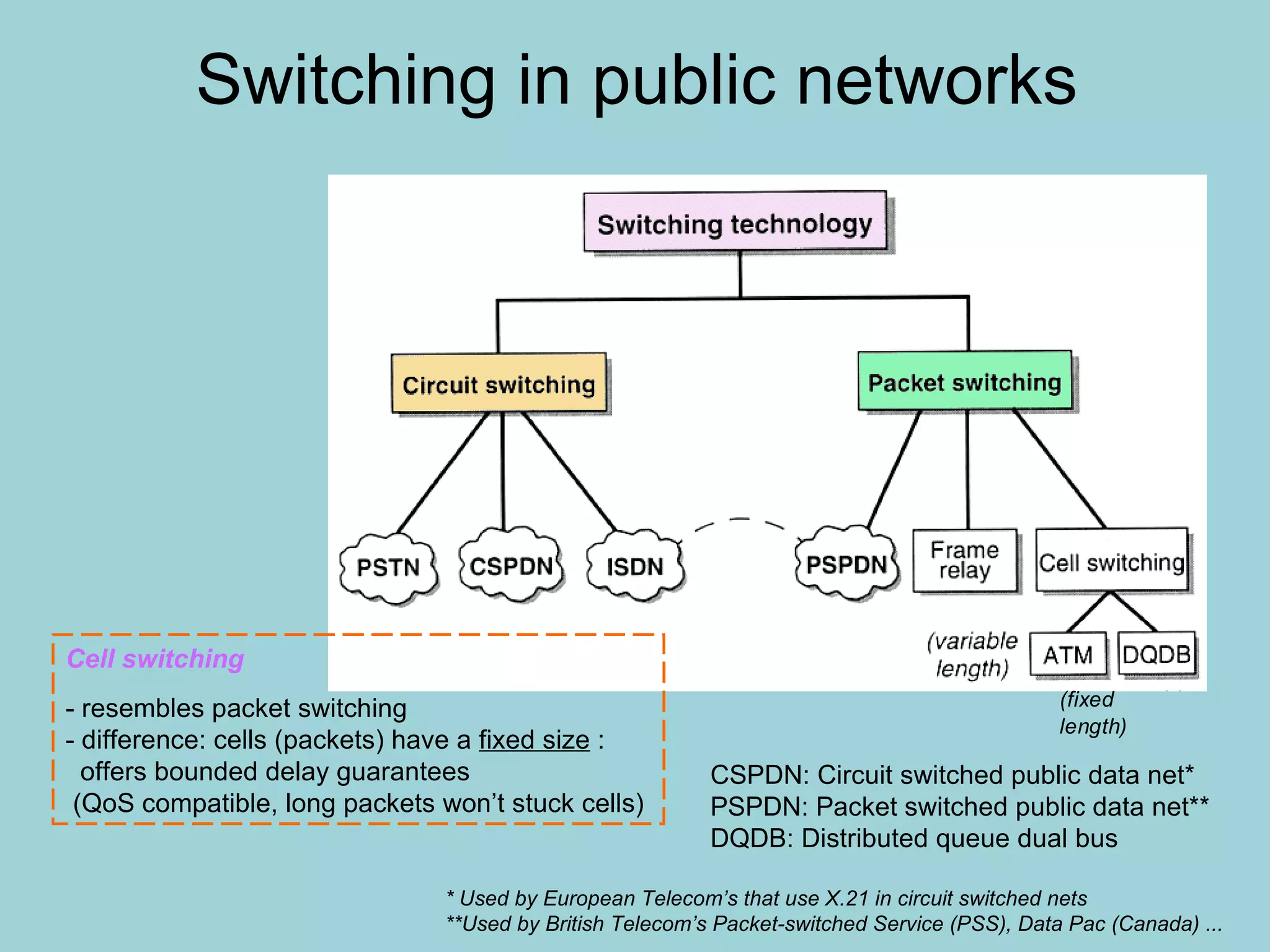
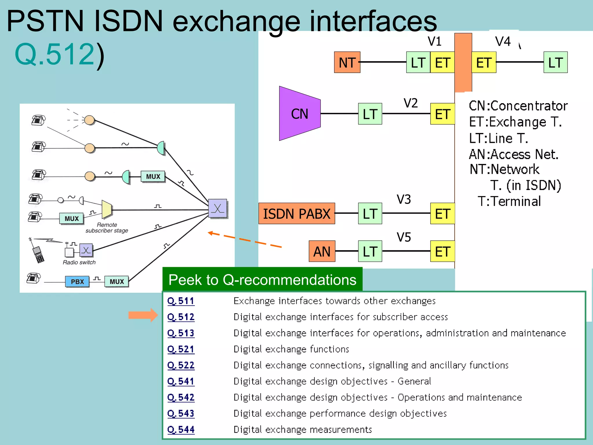
The PSTN – Architecture PSTN – Public Switched Telephone Network Uses digital trunks between Central Office switches (CO) Uses analog line from phones to CO Analog Digital Analog Digital Trunks Analog line Central Office  (CO)
The PSTN – Digitization Voice frequency is 100 - 5000 Hz, with the main portion from 300 – 3400 Hz Nyquist Theorem states that sampling must be done at twice the highest frequency to recreate. 4000 Hz was chosen as the maximum frequency, thus sampling at 8000 Hz PCM = 8kHz * 8 bits per sample =  64 kbit/s
Public Switched Telephone Network Three major components of PSTN: Local loops Trunks Switching Offices Local CO 408-527-xxxx 22,000 in US 1-10 Km CAT 3 Tandem (class 4) Mostly fiber or microwave running  ATM or IP (MCI, Sprint, ATT)
PSTN A: Switching types Connectionless/ connection oriented Packet/circuit B: PSTN exchanges and interfaces interface Q.512 using access and trunk networks signaling network management internetworking (telecommunications between networks)
Switching in public networks CSPDN: Circuit switched public data net* PSPDN: Packet switched public data net** DQDB: Distributed queue dual bus * Used by European Telecom’s that use X.21 in circuit switched nets **Used by British Telecom’s Packet-switched Service (PSS), Data Pac (Canada) ... Cell switching   - resembles packet switching - difference: cells (packets) have a  fixed size  :    offers bounded delay guarantees   (QoS compatible, long packets won’t stuck cells)
Circuit switching Time switch - Makes switching between time slots - In the figure incoming slot 3 is moved to    outgoing slot 3 for one voice direction - Each coming timeslot stored in Speech Store (SS) - Control store (CS) determines the order the slot   are read from SS - The info in CS is determined during setup   phase of the call Space switch -  makes switching between PCM lines -  works with  electronic gates controlled by CS Cross-point  controlled  by CS Circuit switching   - dedicated path - constant delay/bandwidth - voice/data - paid by time - examples: PSTN, VPN TDMA
Time Division Multiplexing (E1) The T1 frame is composed of 230 channels  The frame is 193 bits = 1 framing bit + 8 bits * 32 Time Slots (TS) Framing bit creates an additional channel of 8 kb/s   Frame rate is 8 KHz, each channel is 8K * 7 bits = 56 Kbps The extra bit is used for CAS (Channel Associated Signaling) E1 32 channels, 2.048 MHz = 32 ch * 8K * 8 bits/ch, CCS PCM voice or data
Packet switching Node structure Packet structure Seq:  sequence number Op code: message/control   identifier CRC:  Cyclic Redundancy   Code Note:  - source address required for retransmission in ARQ - byte count could be also an   end flag
Connection-oriented and connectionless switching Connection oriented - Applies same route - QoS well defined  - Phases    - Connection setup   - Data transmission   - Release - Packets received in same order - Example: ATM, frame relay, PCM Connectionless - Use of different routes for    each packet possible - Each packet have address fields - QoS not guaranteed - Packets may come in different order  - Example: IP (Internet Protocol),   TCP takes care of cleaning the mess
Transfer modes & connections summarized Circuit switching Packet switching Connection oriented Connectionless - hand-shaking - strict error requirements - for fast data transfer - broadcasting - modest error rates   often accepted - fast data in good channels Transfer modes Connection types - developed for data - nowadays also for voice - Statistical multiplexing - variable delays - developed for voice - nowadays also for data - well-specified delays - echo problems PSTN ISDN PCM IP, Frame-relay ATM X.25 ATM Frame-relay IP, UDP* *User Datagram Protocol
Packet Switching A comparison of circuit switched and packet-switched networks.
The Local Loop (Last Mile) Modems, ADSL, and Wireless Use both analog and digital transmissions (E1) Conversion is done by the modems and codecs. Transmission problems :  Attenuation (loss of energy), delay distortion (propagation speed vs freq), noise (white noise, crosstalk, impulse noise)
Integrated Services Digital  Network( ISDN ) Telephone network Digital data network Facsimile network Telex network Services and network integrations ISDN Digital technologies Computer control technologies
ISDN Basic Rate Interface (BRI) B B D 64 kbit/s 64 kbit/s 16 kbit/s Basic rate interface (2B+D) 144 kbit/s B ch for information transfer D ch for signaling transfer 2B+D
Primary Rate Interface   (PRI)  D B B B 30B+D 64 kbit/s 64 kbit/s 64 kbit/s 64 kbit/s Primary Rate Interface (2.048 Mbit/s) 30 B channels
Broadband ISDN  Today’s N-ISDN Circuit switched network Packet switched network
To be integrated by B-ISDN ATM and  Optical Fiber Network Broadband ISDN (continued)
ATM (Asynchronous Transfer Mode) Information  (48 Bytes) Header (5Bytes) ATM Cell Structure Incoming data is chopped every 48 bytes, added a header then an ATM cell is formed. Transmission and switching are conducted by cell basis.
STM/ATM STM MUX # 1 # 4 # 3 # 2 STM MUX STM: Synchronous Transfer Mode # 1 # 4 # 3 # 2 ATM MUX
Example of cell switching:  Distributed queue dual buss (DQDB) Function -  transport units  constant length -  access units  access   info in the ring: - know subscribers in access unit’s subnets and route packets for them - access protocol applies  token ring Properties - distributed switching (Compare    to FDDI*)  - ATM compatible - rates: 64 kb/s ... 45 Mb/s - geographical limit up to 200 km *FDDI: Fiber Distributed Data Interface see:  http://www.iol.unh.edu/training/fddi/htmls/ Transport Unit (same as in ATM)
Connecting into PSTN exchange: Equipment in the access network ISDN connection example: 30B+D (2.048 Mb/s) Twisted pair - connection Private Branch Exchange Multiplexer On-line subscriber with several telephones Business subscriber Wireless access (or radio access point) Distribution point Cross connection point ISDN 2B+D 144 kb/s Q.512 specifies exchange interfaces
Local exchange Switch ETC: Exchange terminal circuit IN: Intelligent network conference calls, call waiting, broadcasting ... Signaling (SS7) with users and  other exchanges Traffic concentration - Operation & maintenance support (Q.513)  - Charging - Supplementary (IN) services  - Subscriber data, switch control Control
Subscriber stage To  ETC ETC: Exchange terminal circuit Speech store: shift registers storing bits for time switching Control store: gates guiding speech store switches Connects to: digit receivers, info tones, test equipment Control System: subscriber  authentication, routing, billing, O & M, ... Concentrator internet access (DSLAM) centrex service   MUX
Exchange control functions Maintenance  functions supervision of subscriber lines and trunk circuits Operational  functions administrative  data as subscriber database routing database statistical  data as from where and whom subscribers call holding times for different equipment types utilization of IN services User services Sample of IN services
Exchange user services (examples)   Absent-subscriber  services as the answering machine Call booking : connection at the desired time Person-to-person call : ensures that call goes to a right person Serial call : setting up several calls Telephone conferencing : several persons participate to call in real-time (compare: tele-conferencing) Directory inquiries : also speech recognition, recorded messages (many of these nowadays available in terminals)
The space-switch  (used as a cross-switch and concentrator) Number of cross-connections reduced compared if a simple space division matrix of NxM (input x output) would be used Usually performs concentration: Blocking possible Same signal can be routed via different paths: increased reliability
The time-switch One of the time slots of any  full-duplex  lines is connected to some other line (at a time) Thus two switches / time slot connect a line For 100 full-duplex lines at 19.6 kbps a 1.92 Mbps bus is thus required for no blocking If no fixed assignment of input lines to time slot but on demand allocation -> blocking switch that reduces number of switches and switch clock frequency. For instance 200 lines of 19.6 kbps with bus of 1.92 Mbps  -> about half of the devices can connect at any time, eg concentration is 2:1
The time-space-time (TST) switch Works in local exchange and subscriber stage Performs PCM concentration, usually 10:1 … 3:1  Connects subscribers also to information tones  and test equipment Time switch contains one bus for incoming and outgoing calls (full-duplex)
PSTN ISDN exchange interfaces    Q.512 ) NT:Network    T. (in ISDN)  T:Terminal V4 Peek to Q-recommendations
Exchange interfaces and tasks, V1 Purpose of exchange is to organizes connection between exchange terminators! V1:  Access to basic ISDN  (This is user’s ISDN-u interface that can be used to connect small PBX also) Basic ISDN V1-functions: 2 B + D (2x64 kbps + 16 kbps) channeling structure  timing and frame synchronization activate and deactivate terminator  operation and maintenance feeding power supply ISDN basic access parameters defined in G.961
Exchange interfaces and tasks, V2-V4 V2: Interface  serves typically   concentrators   2048 kbit/s eg  30 B + D  Electrical standard G.704  V3: Resembles V2 but intended for  interface other exchanges (PABX)  Electrical standard G.703 30 B + D at 2048 kb/s also 23 B +D at 1544 kb/s (I.431) V4:Interface to  private networks  (not ITU-T specified), for instance DSLAM (ADSL-interface)
Exchange interfaces and tasks, V5 Between  access network and exchange 2048 kbit/s Specifies basic interfaces for  Analog access  ISDN-access Electrical interface G.703 Channel control and signaling  V5 supports interface rates 2048 kbit/s … 8448 kbit/s
Connecting the local loop:  Line interface circuit (LIC) Used for signaling in certain  coin-operated pay-phones and PBX
Line interface circuit components Over-voltage protection Test equipment to connect to monitor the line condition faults Voltage feed ringing telephone current supply Detection of  hook stage, pulse generated, or dual-tone receiver The hybrid junction (2 wire - 4 wire interface) An A/D converter (uses PCM techniques at 64 kbps)
The hybrid circuit 4-wire connection is used between exchanges and 2-wire connections from exchange to subscribers Two-wire
The  hybrid-circuit If the impedance Z b  equals the line impedance no incoming voice (down right) leaks to outgoing voice (up right) but the signal goes via the two wire connection on the left   To exchange From exchange Local loop
The hybrid circuit   summarized The hybrid circuit  transforms  two-wire connection into 4-wire connection. If the hybrid is unbalanced  echo  will result Hybrid is  balanced  when no own voice is leaked into own loudspeaker Hybrid unbalance can result from  line impedance  changes due to weather conditions Unbalance results  echo Echo  cancellation  circuits are harmful in data connections Now a days realized by  operational amplifier  based circuitry that automatically monitors line impedance changes
Network echo suppressor R: transmission gate, A: attenuator, L: logic circuit When the signal is present on the receiving line the transmitting line is  cut-off A kind of semi-duplex approach to solve the echo problem
Network echo canceller (NEC) Signal echo is extracted and  subtracted  from the received signal More effective than echo suppressor. Often NEC and NES are however both used
PSTN operation and maintenance Different alarm classes Vital functions and circuits   (as SS7 and group switch)  use secured paths and  backups  Procedures provided for: troubleshooting fault diagnostics hardware faults can be isolated Supervision is realized also by connecting maintenance units to the network Important switches have extensive backup equipment A supervision plan by network levels:
Modern PSTN hierarchy
PSTN Hierarchy cont. Local  (example, within a city) Subscriber connections Switching within the local exchange Switching to other exchanges Transit  (county level, say between Tampere and Helsinki) Switching traffic between different geographical areas within one country International Gateway-type traffic between  different countries DWDM (Dense Wavelength Division Multiplexing) routes Rates can follow SONET or SDH standard SDH -  transport of 1.5/2/6/34/45/140 Mbps within a transmission rate of 155.52 Mbps  - carries for instance ATM and IP within rates that are integer multiples of 155.52 Mbps
Subscriber signaling for local calls
Inter-exchange signaling Channel associated signaling ( CAS ) as No.5, R1, R2 analog and digital connections Modern ISDN exchanges apply SS7(digital), that is a common channel signaling method ( CSS ) that is discussed later in its own lecture CAS  is divided into  line and register signaling : Line  signaling: line state between the trunk-links as answer, clear-forward*, clear-back Register  signaling: routing information as B-number, A-category, B-status *A-subscriber on-hook message transmitted to B exchange
Inter exchange signaling (cont.) Three categories of information is transmitted: setup , supervision clearing service  related information as forwarding, callback, charging status  change information transmission network congestion neighborhood exchange congestion
Example of inter-exchange signaling
Inter-exchange signaling (cont.)

How PSTN phone works?

  • 1.
    The PSTN –Architecture PSTN – Public Switched Telephone Network Uses digital trunks between Central Office switches (CO) Uses analog line from phones to CO Analog Digital Analog Digital Trunks Analog line Central Office (CO)
  • 2.
    The PSTN –Digitization Voice frequency is 100 - 5000 Hz, with the main portion from 300 – 3400 Hz Nyquist Theorem states that sampling must be done at twice the highest frequency to recreate. 4000 Hz was chosen as the maximum frequency, thus sampling at 8000 Hz PCM = 8kHz * 8 bits per sample = 64 kbit/s
  • 3.
    Public Switched TelephoneNetwork Three major components of PSTN: Local loops Trunks Switching Offices Local CO 408-527-xxxx 22,000 in US 1-10 Km CAT 3 Tandem (class 4) Mostly fiber or microwave running ATM or IP (MCI, Sprint, ATT)
  • 4.
    PSTN A: Switchingtypes Connectionless/ connection oriented Packet/circuit B: PSTN exchanges and interfaces interface Q.512 using access and trunk networks signaling network management internetworking (telecommunications between networks)
  • 5.
    Switching in publicnetworks CSPDN: Circuit switched public data net* PSPDN: Packet switched public data net** DQDB: Distributed queue dual bus * Used by European Telecom’s that use X.21 in circuit switched nets **Used by British Telecom’s Packet-switched Service (PSS), Data Pac (Canada) ... Cell switching - resembles packet switching - difference: cells (packets) have a fixed size : offers bounded delay guarantees (QoS compatible, long packets won’t stuck cells)
  • 6.
    Circuit switching Timeswitch - Makes switching between time slots - In the figure incoming slot 3 is moved to outgoing slot 3 for one voice direction - Each coming timeslot stored in Speech Store (SS) - Control store (CS) determines the order the slot are read from SS - The info in CS is determined during setup phase of the call Space switch - makes switching between PCM lines - works with electronic gates controlled by CS Cross-point controlled by CS Circuit switching - dedicated path - constant delay/bandwidth - voice/data - paid by time - examples: PSTN, VPN TDMA
  • 7.
    Time Division Multiplexing(E1) The T1 frame is composed of 230 channels The frame is 193 bits = 1 framing bit + 8 bits * 32 Time Slots (TS) Framing bit creates an additional channel of 8 kb/s Frame rate is 8 KHz, each channel is 8K * 7 bits = 56 Kbps The extra bit is used for CAS (Channel Associated Signaling) E1 32 channels, 2.048 MHz = 32 ch * 8K * 8 bits/ch, CCS PCM voice or data
  • 8.
    Packet switching Nodestructure Packet structure Seq: sequence number Op code: message/control identifier CRC: Cyclic Redundancy Code Note: - source address required for retransmission in ARQ - byte count could be also an end flag
  • 9.
    Connection-oriented and connectionlessswitching Connection oriented - Applies same route - QoS well defined - Phases - Connection setup - Data transmission - Release - Packets received in same order - Example: ATM, frame relay, PCM Connectionless - Use of different routes for each packet possible - Each packet have address fields - QoS not guaranteed - Packets may come in different order - Example: IP (Internet Protocol), TCP takes care of cleaning the mess
  • 10.
    Transfer modes &connections summarized Circuit switching Packet switching Connection oriented Connectionless - hand-shaking - strict error requirements - for fast data transfer - broadcasting - modest error rates often accepted - fast data in good channels Transfer modes Connection types - developed for data - nowadays also for voice - Statistical multiplexing - variable delays - developed for voice - nowadays also for data - well-specified delays - echo problems PSTN ISDN PCM IP, Frame-relay ATM X.25 ATM Frame-relay IP, UDP* *User Datagram Protocol
  • 11.
    Packet Switching Acomparison of circuit switched and packet-switched networks.
  • 12.
    The Local Loop(Last Mile) Modems, ADSL, and Wireless Use both analog and digital transmissions (E1) Conversion is done by the modems and codecs. Transmission problems : Attenuation (loss of energy), delay distortion (propagation speed vs freq), noise (white noise, crosstalk, impulse noise)
  • 13.
    Integrated Services Digital Network( ISDN ) Telephone network Digital data network Facsimile network Telex network Services and network integrations ISDN Digital technologies Computer control technologies
  • 14.
    ISDN Basic RateInterface (BRI) B B D 64 kbit/s 64 kbit/s 16 kbit/s Basic rate interface (2B+D) 144 kbit/s B ch for information transfer D ch for signaling transfer 2B+D
  • 15.
    Primary Rate Interface (PRI) D B B B 30B+D 64 kbit/s 64 kbit/s 64 kbit/s 64 kbit/s Primary Rate Interface (2.048 Mbit/s) 30 B channels
  • 16.
    Broadband ISDN Today’s N-ISDN Circuit switched network Packet switched network
  • 17.
    To be integratedby B-ISDN ATM and Optical Fiber Network Broadband ISDN (continued)
  • 18.
    ATM (Asynchronous TransferMode) Information (48 Bytes) Header (5Bytes) ATM Cell Structure Incoming data is chopped every 48 bytes, added a header then an ATM cell is formed. Transmission and switching are conducted by cell basis.
  • 19.
    STM/ATM STM MUX# 1 # 4 # 3 # 2 STM MUX STM: Synchronous Transfer Mode # 1 # 4 # 3 # 2 ATM MUX
  • 20.
    Example of cellswitching: Distributed queue dual buss (DQDB) Function - transport units constant length - access units access info in the ring: - know subscribers in access unit’s subnets and route packets for them - access protocol applies token ring Properties - distributed switching (Compare to FDDI*) - ATM compatible - rates: 64 kb/s ... 45 Mb/s - geographical limit up to 200 km *FDDI: Fiber Distributed Data Interface see: http://www.iol.unh.edu/training/fddi/htmls/ Transport Unit (same as in ATM)
  • 21.
    Connecting into PSTNexchange: Equipment in the access network ISDN connection example: 30B+D (2.048 Mb/s) Twisted pair - connection Private Branch Exchange Multiplexer On-line subscriber with several telephones Business subscriber Wireless access (or radio access point) Distribution point Cross connection point ISDN 2B+D 144 kb/s Q.512 specifies exchange interfaces
  • 22.
    Local exchange SwitchETC: Exchange terminal circuit IN: Intelligent network conference calls, call waiting, broadcasting ... Signaling (SS7) with users and other exchanges Traffic concentration - Operation & maintenance support (Q.513) - Charging - Supplementary (IN) services - Subscriber data, switch control Control
  • 23.
    Subscriber stage To ETC ETC: Exchange terminal circuit Speech store: shift registers storing bits for time switching Control store: gates guiding speech store switches Connects to: digit receivers, info tones, test equipment Control System: subscriber authentication, routing, billing, O & M, ... Concentrator internet access (DSLAM) centrex service MUX
  • 24.
    Exchange control functionsMaintenance functions supervision of subscriber lines and trunk circuits Operational functions administrative data as subscriber database routing database statistical data as from where and whom subscribers call holding times for different equipment types utilization of IN services User services Sample of IN services
  • 25.
    Exchange user services(examples) Absent-subscriber services as the answering machine Call booking : connection at the desired time Person-to-person call : ensures that call goes to a right person Serial call : setting up several calls Telephone conferencing : several persons participate to call in real-time (compare: tele-conferencing) Directory inquiries : also speech recognition, recorded messages (many of these nowadays available in terminals)
  • 26.
    The space-switch (used as a cross-switch and concentrator) Number of cross-connections reduced compared if a simple space division matrix of NxM (input x output) would be used Usually performs concentration: Blocking possible Same signal can be routed via different paths: increased reliability
  • 27.
    The time-switch Oneof the time slots of any full-duplex lines is connected to some other line (at a time) Thus two switches / time slot connect a line For 100 full-duplex lines at 19.6 kbps a 1.92 Mbps bus is thus required for no blocking If no fixed assignment of input lines to time slot but on demand allocation -> blocking switch that reduces number of switches and switch clock frequency. For instance 200 lines of 19.6 kbps with bus of 1.92 Mbps -> about half of the devices can connect at any time, eg concentration is 2:1
  • 28.
    The time-space-time (TST)switch Works in local exchange and subscriber stage Performs PCM concentration, usually 10:1 … 3:1 Connects subscribers also to information tones and test equipment Time switch contains one bus for incoming and outgoing calls (full-duplex)
  • 29.
    PSTN ISDN exchangeinterfaces Q.512 ) NT:Network T. (in ISDN) T:Terminal V4 Peek to Q-recommendations
  • 30.
    Exchange interfaces andtasks, V1 Purpose of exchange is to organizes connection between exchange terminators! V1: Access to basic ISDN (This is user’s ISDN-u interface that can be used to connect small PBX also) Basic ISDN V1-functions: 2 B + D (2x64 kbps + 16 kbps) channeling structure timing and frame synchronization activate and deactivate terminator operation and maintenance feeding power supply ISDN basic access parameters defined in G.961
  • 31.
    Exchange interfaces andtasks, V2-V4 V2: Interface serves typically concentrators 2048 kbit/s eg 30 B + D Electrical standard G.704 V3: Resembles V2 but intended for interface other exchanges (PABX) Electrical standard G.703 30 B + D at 2048 kb/s also 23 B +D at 1544 kb/s (I.431) V4:Interface to private networks (not ITU-T specified), for instance DSLAM (ADSL-interface)
  • 32.
    Exchange interfaces andtasks, V5 Between access network and exchange 2048 kbit/s Specifies basic interfaces for Analog access ISDN-access Electrical interface G.703 Channel control and signaling V5 supports interface rates 2048 kbit/s … 8448 kbit/s
  • 33.
    Connecting the localloop: Line interface circuit (LIC) Used for signaling in certain coin-operated pay-phones and PBX
  • 34.
    Line interface circuitcomponents Over-voltage protection Test equipment to connect to monitor the line condition faults Voltage feed ringing telephone current supply Detection of hook stage, pulse generated, or dual-tone receiver The hybrid junction (2 wire - 4 wire interface) An A/D converter (uses PCM techniques at 64 kbps)
  • 35.
    The hybrid circuit4-wire connection is used between exchanges and 2-wire connections from exchange to subscribers Two-wire
  • 36.
    The hybrid-circuitIf the impedance Z b equals the line impedance no incoming voice (down right) leaks to outgoing voice (up right) but the signal goes via the two wire connection on the left To exchange From exchange Local loop
  • 37.
    The hybrid circuit summarized The hybrid circuit transforms two-wire connection into 4-wire connection. If the hybrid is unbalanced echo will result Hybrid is balanced when no own voice is leaked into own loudspeaker Hybrid unbalance can result from line impedance changes due to weather conditions Unbalance results echo Echo cancellation circuits are harmful in data connections Now a days realized by operational amplifier based circuitry that automatically monitors line impedance changes
  • 38.
    Network echo suppressorR: transmission gate, A: attenuator, L: logic circuit When the signal is present on the receiving line the transmitting line is cut-off A kind of semi-duplex approach to solve the echo problem
  • 39.
    Network echo canceller(NEC) Signal echo is extracted and subtracted from the received signal More effective than echo suppressor. Often NEC and NES are however both used
  • 40.
    PSTN operation andmaintenance Different alarm classes Vital functions and circuits (as SS7 and group switch) use secured paths and backups Procedures provided for: troubleshooting fault diagnostics hardware faults can be isolated Supervision is realized also by connecting maintenance units to the network Important switches have extensive backup equipment A supervision plan by network levels:
  • 41.
  • 42.
    PSTN Hierarchy cont.Local (example, within a city) Subscriber connections Switching within the local exchange Switching to other exchanges Transit (county level, say between Tampere and Helsinki) Switching traffic between different geographical areas within one country International Gateway-type traffic between different countries DWDM (Dense Wavelength Division Multiplexing) routes Rates can follow SONET or SDH standard SDH - transport of 1.5/2/6/34/45/140 Mbps within a transmission rate of 155.52 Mbps - carries for instance ATM and IP within rates that are integer multiples of 155.52 Mbps
  • 43.
  • 44.
    Inter-exchange signaling Channelassociated signaling ( CAS ) as No.5, R1, R2 analog and digital connections Modern ISDN exchanges apply SS7(digital), that is a common channel signaling method ( CSS ) that is discussed later in its own lecture CAS is divided into line and register signaling : Line signaling: line state between the trunk-links as answer, clear-forward*, clear-back Register signaling: routing information as B-number, A-category, B-status *A-subscriber on-hook message transmitted to B exchange
  • 45.
    Inter exchange signaling(cont.) Three categories of information is transmitted: setup , supervision clearing service related information as forwarding, callback, charging status change information transmission network congestion neighborhood exchange congestion
  • 46.
  • 47.