Downloaded 308 times
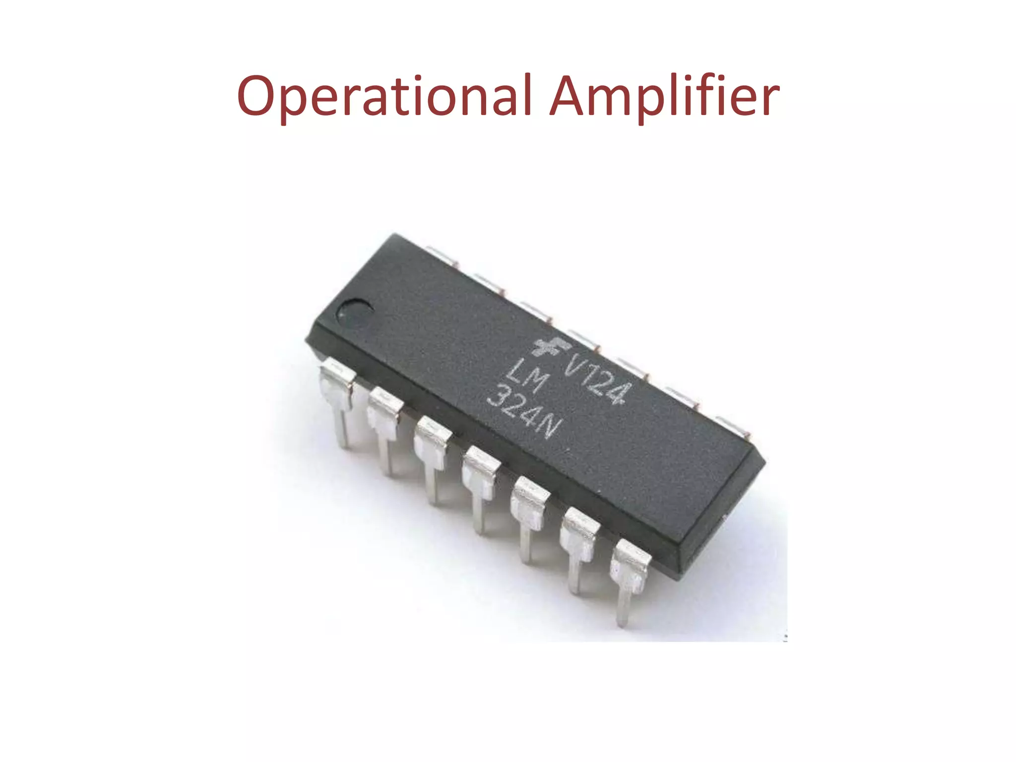
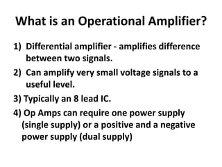
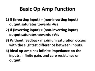
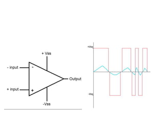
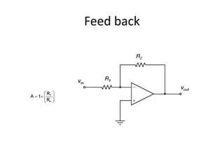
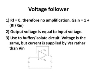


An operational amplifier (op-amp) is a differential amplifier that takes the difference between two input voltages and amplifies it. It can amplify very small voltage signals to a useful level. The op-amp is typically an 8-lead integrated circuit that requires a positive and negative power supply. The degree of amplification can be controlled using feedback, which is most commonly applied to the inverting input as negative feedback. The gain is determined by the formula Gain = 1 + (Rf/Rin). Some common op-amp configurations include the voltage follower, comparator, and non-inverting amplifier.


