Downloaded 118 times
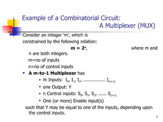
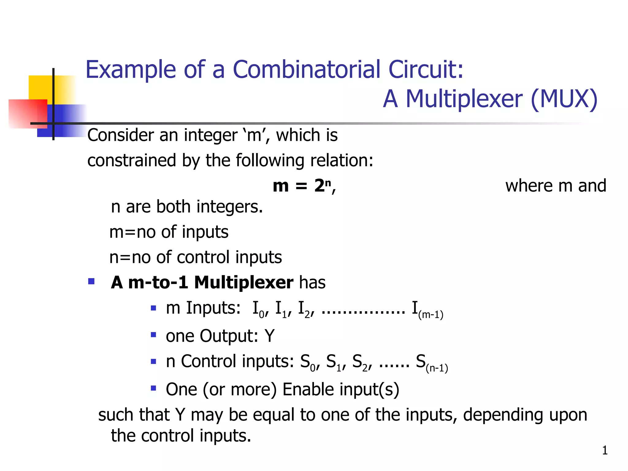
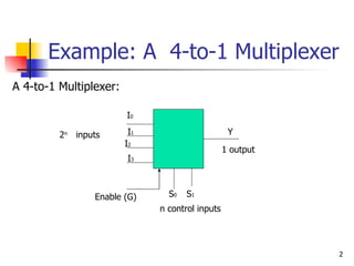
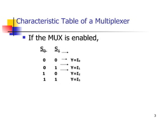
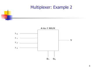
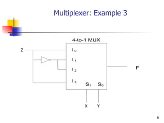
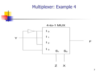
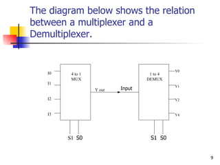

1) A multiplexer is a combinational circuit with m inputs, n control inputs, and 1 output that can select one of the m inputs to pass to the output based on the values of the n control inputs. 2) A 4-to-1 multiplexer has 4 inputs, 2 control inputs, and 1 output. The output will be one of the 4 inputs depending on the binary values of the 2 control inputs. 3) A demultiplexer is the opposite of a multiplexer, taking a single input and distributing it to one of multiple outputs based on the control inputs. It can also be used as a decoder to output a binary word based on the control input code.