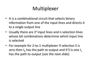
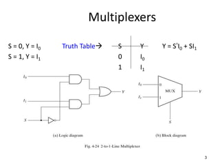
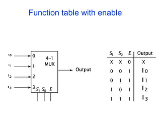
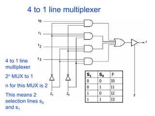
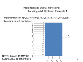
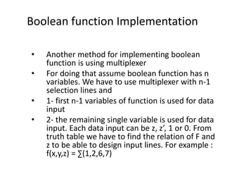
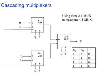
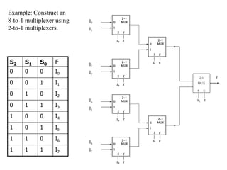
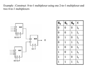
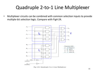
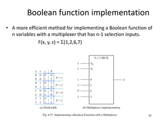
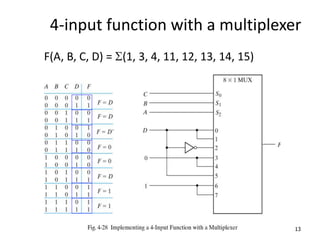
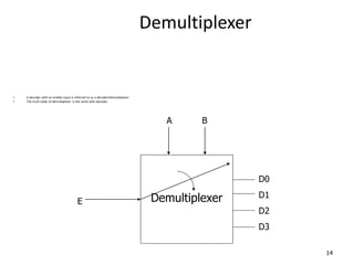
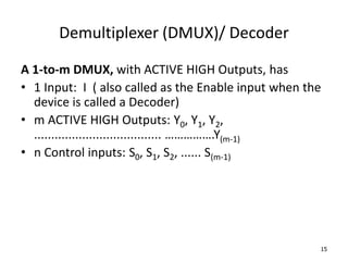
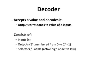
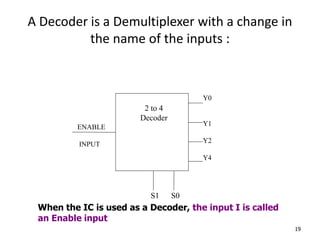
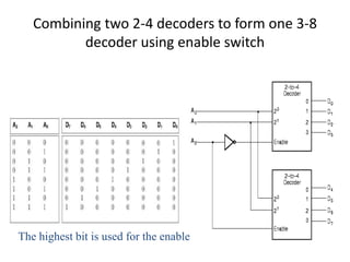
Combinational Logic Design
Unit II
Multiplexer
• It is a combinational circuit that selects binary
information from one of the input lines and directs it
to a single output line
• Usually there are 2n input lines and n selection lines
whose bit combinations determine which input line
is selected
• For example for 2-to-1 multiplexer if selection S is
zero then I0 has the path to output and if S is one I1
has the path to output (see the next slide)
Multiplexers
S = 0, Y = I0 Truth Table S Y Y = S’I0 + SI1
S = 1, Y = I1 0 I0
1 I1
3
Function table with enable
4 to 1 line multiplexer
S1 S0 F
0 0 I0
0 1 I1
1 0 I2
1 1 I3
4 to 1 line
multiplexer
2n MUX to 1
n for this MUX is 2
This means 2
selection lines s0
and s1
Implementing Digital Functions:
by using a Multiplexer: Example 1
Implementation of F(A,B,C,D)=∑ (m(1,3,5,7,8,10,12,13,14), d(4,6,15))
By using a 16-to-1 multiplexer:
6
F
I0
0
0
1
0
NOTE: 4,6 and 15 MAY BE
CONNECTED to either 0 or 1
I1
I2
I3
I4
I5
I8
I6
I9
I7
I11
I10
I13
I12
I14
I15
0
0
0
0
1
1
1
1
1
1
1
1
S3 S2 S1 S0
Boolean function Implementation
• Another method for implementing boolean
function is using multiplexer
• For doing that assume boolean function has n
variables. We have to use multiplexer with n-1
selection lines and
• 1- first n-1 variables of function is used for data
input
• 2- the remaining single variable is used for data
input. Each data input can be z, z’, 1 or 0. From
truth table we have to find the relation of F and
z to be able to design input lines. For example :
f(x,y,z) = ∑(1,2,6,7)
Cascading multiplexers
Using three 2-1 MUX
to make one 4-1 MUX
S1 S0 F
0 0 I0
0 1 I1
1 0 I2
1 1 I3
F
F
2-1
MUX
S E
S2 E
S2 S1 S0 F
0 0 0 I0
0 0 1 I1
0 1 0 I2
0 1 1 I3
1 0 0 I4
1 0 1 I5
1 1 0 I6
1 1 1 I7
I0
I1
I2
I3
I4
I5
I6
I7
Example: Construct an
8-to-1 multiplexer using
2-to-1 multiplexers.
Example : Construct 8-to-1 multiplexer using one 2-to-1 multiplexer and
two 4-to-1 multiplexers
S2 S1 S0 X
0 0 0 I0
0 0 1 I1
0 1 0 I2
0 1 1 I3
1 0 0 I4
1 0 1 I5
1 1 0 I6
1 1 1 I7
Quadruple 2-to-1 Line Multiplexer
• Multiplexer circuits can be combined with common selection inputs to provide
multiple-bit selection logic. Compare with Fig4-24.
11
I0
I1
Y
Boolean function implementation
• A more efficient method for implementing a Boolean function of
n variables with a multiplexer that has n-1 selection inputs.
F(x, y, z) = (1,2,6,7)
12
4-input function with a multiplexer
F(A, B, C, D) = (1, 3, 4, 11, 12, 13, 14, 15)
13
Demultiplexer
• A decoder with an enable input is referred to as a decoder/demultiplexer.
• The truth table of demultiplexer is the same with decoder.
14
Demultiplexer
D0
D1
D2
D3
E
A B
Demultiplexer (DMUX)/ Decoder
A 1-to-m DMUX, with ACTIVE HIGH Outputs, has
• 1 Input: I ( also called as the Enable input when the
device is called a Decoder)
• m ACTIVE HIGH Outputs: Y0, Y1, Y2,
..................................... …………….Y(m-1)
• n Control inputs: S0, S1, S2, ...... S(m-1)
15
Characteristic table of the 1-to-4 DMUX
with ACTIVE HIGH Outputs:
16
Table 2
Characteristic Table of a 1-to-4 DMUX, with
ACTIVE LOW Outputs:
17
Table 3
Decoder
– Accepts a value and decodes it
• Output corresponds to value of n inputs
– Consists of:
• Inputs (n)
• Outputs (2n , numbered from 0  2n - 1)
• Selectors / Enable (active high or active low)
A Decoder is a Demultiplexer with a change in
the name of the inputs :
19
Y0
Y1
Y2
Y4
S1 S0
ENABLE
INPUT
2 to 4
Decoder
When the IC is used as a Decoder, the input I is called
an Enable input
The truth table of 2-to-4 Decoder
2-to-4 Decoder
2-to-4 Decoder
The truth table of 3-to-8 Decoder
A2 A1 A0 D0 D1 D2 D3 D4 D5 D6 D7
0 0 0 1
0 0 1 1
0 1 0 1
0 1 1 1
1 0 0 1
1 0 1 1
1 1 0 1
1 1 1 1
3-to-8 Decoder
3-to-8 Decoder with Enable
Decoder with enable input
• Some decoders are constructed with NAND gates, it becomes more economical to generate the decoder minterms in their complemented form.
• As indicated by the truth table , only one output can be equal to 0 at any given time, all other outputs are equal to 1.
26
3-to-8 decoder with enable implement the
4-to-16 decoder
27
Implementation of a Full Adder with a
Decoder
• From table 4-4, we obtain the functions for the combinational circuit in sum of
minterms:
S(x, y, z) = ∑(1, 2, 4, 7)
C(x, y, z) = ∑(3, 5, 6, 7)
28
Decoders: Implementing Functions
• Example: Full adder
S(x, y, z) =  m(1,2,4,7)
C(x, y, z) =  m(3,5,6,7)
3x8
Dec
S2
S1
S0
x
y
z
0
1
2
3
4
5
6
7
S
C
x y z C S
0 0 0 0 0
0 0 1 0 1
0 1 0 0 1
0 1 1 1 0
1 0 0 0 1
1 0 1 1 0
1 1 0 1 0
1 1 1 1 1
From Figure
Decoder Expansion
• Decoder expansion
– Combine two or more small decoders with enable
inputs to form a larger decoder
– 3-to-8-line decoder constructed from two 2-to-4-
line decoders
• The MSB is connected to the enable inputs
• if A2=0, upper is enabled; if A2=1, lower is
enabled.
Decoder Expansion
Combining two 2-4 decoders to form one 3-8
decoder using enable switch
The highest bit is used for the enables
How about 4-16 decoder
• Use how many 3-8 decoder?
• Use how many 2-4 decoder?
Characteristic table of the 1-to-4 DMUX
with ACTIVE HIGH Outputs:
34
Table 2
Characteristic Table of a 1-to-4 DMUX, with
ACTIVE LOW Outputs:
35
Table 3

minimization technique.ppt

  • 1.
  • 2.
    Multiplexer • It isa combinational circuit that selects binary information from one of the input lines and directs it to a single output line • Usually there are 2n input lines and n selection lines whose bit combinations determine which input line is selected • For example for 2-to-1 multiplexer if selection S is zero then I0 has the path to output and if S is one I1 has the path to output (see the next slide)
  • 3.
    Multiplexers S = 0,Y = I0 Truth Table S Y Y = S’I0 + SI1 S = 1, Y = I1 0 I0 1 I1 3
  • 4.
  • 5.
    4 to 1line multiplexer S1 S0 F 0 0 I0 0 1 I1 1 0 I2 1 1 I3 4 to 1 line multiplexer 2n MUX to 1 n for this MUX is 2 This means 2 selection lines s0 and s1
  • 6.
    Implementing Digital Functions: byusing a Multiplexer: Example 1 Implementation of F(A,B,C,D)=∑ (m(1,3,5,7,8,10,12,13,14), d(4,6,15)) By using a 16-to-1 multiplexer: 6 F I0 0 0 1 0 NOTE: 4,6 and 15 MAY BE CONNECTED to either 0 or 1 I1 I2 I3 I4 I5 I8 I6 I9 I7 I11 I10 I13 I12 I14 I15 0 0 0 0 1 1 1 1 1 1 1 1 S3 S2 S1 S0
  • 7.
    Boolean function Implementation •Another method for implementing boolean function is using multiplexer • For doing that assume boolean function has n variables. We have to use multiplexer with n-1 selection lines and • 1- first n-1 variables of function is used for data input • 2- the remaining single variable is used for data input. Each data input can be z, z’, 1 or 0. From truth table we have to find the relation of F and z to be able to design input lines. For example : f(x,y,z) = ∑(1,2,6,7)
  • 8.
    Cascading multiplexers Using three2-1 MUX to make one 4-1 MUX S1 S0 F 0 0 I0 0 1 I1 1 0 I2 1 1 I3 F
  • 9.
    F 2-1 MUX S E S2 E S2S1 S0 F 0 0 0 I0 0 0 1 I1 0 1 0 I2 0 1 1 I3 1 0 0 I4 1 0 1 I5 1 1 0 I6 1 1 1 I7 I0 I1 I2 I3 I4 I5 I6 I7 Example: Construct an 8-to-1 multiplexer using 2-to-1 multiplexers.
  • 10.
    Example : Construct8-to-1 multiplexer using one 2-to-1 multiplexer and two 4-to-1 multiplexers S2 S1 S0 X 0 0 0 I0 0 0 1 I1 0 1 0 I2 0 1 1 I3 1 0 0 I4 1 0 1 I5 1 1 0 I6 1 1 1 I7
  • 11.
    Quadruple 2-to-1 LineMultiplexer • Multiplexer circuits can be combined with common selection inputs to provide multiple-bit selection logic. Compare with Fig4-24. 11 I0 I1 Y
  • 12.
    Boolean function implementation •A more efficient method for implementing a Boolean function of n variables with a multiplexer that has n-1 selection inputs. F(x, y, z) = (1,2,6,7) 12
  • 13.
    4-input function witha multiplexer F(A, B, C, D) = (1, 3, 4, 11, 12, 13, 14, 15) 13
  • 14.
    Demultiplexer • A decoderwith an enable input is referred to as a decoder/demultiplexer. • The truth table of demultiplexer is the same with decoder. 14 Demultiplexer D0 D1 D2 D3 E A B
  • 15.
    Demultiplexer (DMUX)/ Decoder A1-to-m DMUX, with ACTIVE HIGH Outputs, has • 1 Input: I ( also called as the Enable input when the device is called a Decoder) • m ACTIVE HIGH Outputs: Y0, Y1, Y2, ..................................... …………….Y(m-1) • n Control inputs: S0, S1, S2, ...... S(m-1) 15
  • 16.
    Characteristic table ofthe 1-to-4 DMUX with ACTIVE HIGH Outputs: 16 Table 2
  • 17.
    Characteristic Table ofa 1-to-4 DMUX, with ACTIVE LOW Outputs: 17 Table 3
  • 18.
    Decoder – Accepts avalue and decodes it • Output corresponds to value of n inputs – Consists of: • Inputs (n) • Outputs (2n , numbered from 0  2n - 1) • Selectors / Enable (active high or active low)
  • 19.
    A Decoder isa Demultiplexer with a change in the name of the inputs : 19 Y0 Y1 Y2 Y4 S1 S0 ENABLE INPUT 2 to 4 Decoder When the IC is used as a Decoder, the input I is called an Enable input
  • 20.
    The truth tableof 2-to-4 Decoder
  • 21.
  • 22.
  • 23.
    The truth tableof 3-to-8 Decoder A2 A1 A0 D0 D1 D2 D3 D4 D5 D6 D7 0 0 0 1 0 0 1 1 0 1 0 1 0 1 1 1 1 0 0 1 1 0 1 1 1 1 0 1 1 1 1 1
  • 24.
  • 25.
  • 26.
    Decoder with enableinput • Some decoders are constructed with NAND gates, it becomes more economical to generate the decoder minterms in their complemented form. • As indicated by the truth table , only one output can be equal to 0 at any given time, all other outputs are equal to 1. 26
  • 27.
    3-to-8 decoder withenable implement the 4-to-16 decoder 27
  • 28.
    Implementation of aFull Adder with a Decoder • From table 4-4, we obtain the functions for the combinational circuit in sum of minterms: S(x, y, z) = ∑(1, 2, 4, 7) C(x, y, z) = ∑(3, 5, 6, 7) 28
  • 29.
    Decoders: Implementing Functions •Example: Full adder S(x, y, z) =  m(1,2,4,7) C(x, y, z) =  m(3,5,6,7) 3x8 Dec S2 S1 S0 x y z 0 1 2 3 4 5 6 7 S C x y z C S 0 0 0 0 0 0 0 1 0 1 0 1 0 0 1 0 1 1 1 0 1 0 0 0 1 1 0 1 1 0 1 1 0 1 0 1 1 1 1 1 From Figure
  • 30.
    Decoder Expansion • Decoderexpansion – Combine two or more small decoders with enable inputs to form a larger decoder – 3-to-8-line decoder constructed from two 2-to-4- line decoders • The MSB is connected to the enable inputs • if A2=0, upper is enabled; if A2=1, lower is enabled.
  • 31.
  • 32.
    Combining two 2-4decoders to form one 3-8 decoder using enable switch The highest bit is used for the enables
  • 33.
    How about 4-16decoder • Use how many 3-8 decoder? • Use how many 2-4 decoder?
  • 34.
    Characteristic table ofthe 1-to-4 DMUX with ACTIVE HIGH Outputs: 34 Table 2
  • 35.
    Characteristic Table ofa 1-to-4 DMUX, with ACTIVE LOW Outputs: 35 Table 3